Validation
What You Will Do
In this chapter you deliberately put three defects into the topology finished in LIN Bus and see how PAIO validation reports them. PAIO validates the open project by itself, so you only open the VALIDATION panel with the V icon in the footer and read the three error rows and the badge 3. You then click the rows to move close to the problem elements, fix the values on screen and save.
There are three places to fix. You restore the unicast address of the Ethernet connector EthernetConnector of HPC to 192.168.0.11, assign the controller LinSlaveController to the LIN connector LinConnector of SLAVE_ECU again, and restore the protocol version of the LIN slave controller LinSlaveController to LIN 2.0. The connector of HPC is shown as a full procedure from start to finish, and the other two follow the same flow.
When you finish this chapter, the VALIDATION panel shows No validation issues.. The fixed topology is the same as the design finished in LIN Bus.
Before You Begin
- Start after finishing LIN Bus. At that point the VALIDATION panel shows
No validation issues.. - The screens in this chapter show that design with the three defects below. No editor is open, and the VALIDATION panel is closed.
| Defect | Location | Original value | Changed value |
|---|---|---|---|
The unicast address of the HPC connector is a multicast address | UNICAST IPV4 ADDRESS of EthernetConnector on the node HPC | 192.168.0.11 | 224.0.0.1 |
The SLAVE_ECU connector has no controller | CONTROLLER of LinConnector on the node SLAVE_ECU | LinSlaveController | Empty (Select controller...) |
| The LIN slave controller has no protocol version | PROTOCOL VERSION of LinSlaveController on the node SLAVE_ECU | LIN 2.0 | Empty (no button on) |
Note. All three defects can be made on screen. In the EDITOR view, click System under DESIGN to open the tab
TopologyDesign:System, make the changes below and save withCtrl+S. After saving, click the × of the tabTopologyDesign:Systemto close it, and if the VALIDATION panel is open, click the V icon in the footer to close it. This way you start from the same state as the screens of this chapter (Figure 6-1). For the first, clickEthernetConnectorofHPC, type224.0.0.1into UNICAST IPV4 ADDRESS and press theTabkey. The field accepts this value as is and does not mark it as an error. For the second, clickLinConnectorofSLAVE_ECUand click the × (Clear Controller) inside the CONTROLLER field, to the left of the down arrow. The field changes toSelect controller..., and its label turns red with the hintController is required. The × is visible only while the field has a value. For the third, clickLinSlaveControllerand clickLIN 2.0under PROTOCOL VERSION once more to turn it off. No button stays on.
The only value you type on the keyboard in this chapter is 192.168.0.11 in UNICAST IPV4 ADDRESS. Everything else is clicks, drop-down choices and Ctrl+S.
Running Validation and Reading the VALIDATION Panel
Opening the VALIDATION Panel
-
Look at the V icon in the footer at the bottom left of the screen. PAIO validates the open project by itself, without opening an editor, so the icon already carries a red badge
3. Hovering over the icon shows the tooltipValidation: 3 error(s), 0 warning(s), 0 info(s). -
Click the V icon in the footer. The VALIDATION panel opens at the bottom of the screen. Next to the title is a red badge
3(tooltip3 error(s)), and the column headers are ELEMENT TYPE, NAME, DESCRIPTION and CONSTR. Below them are three error rows.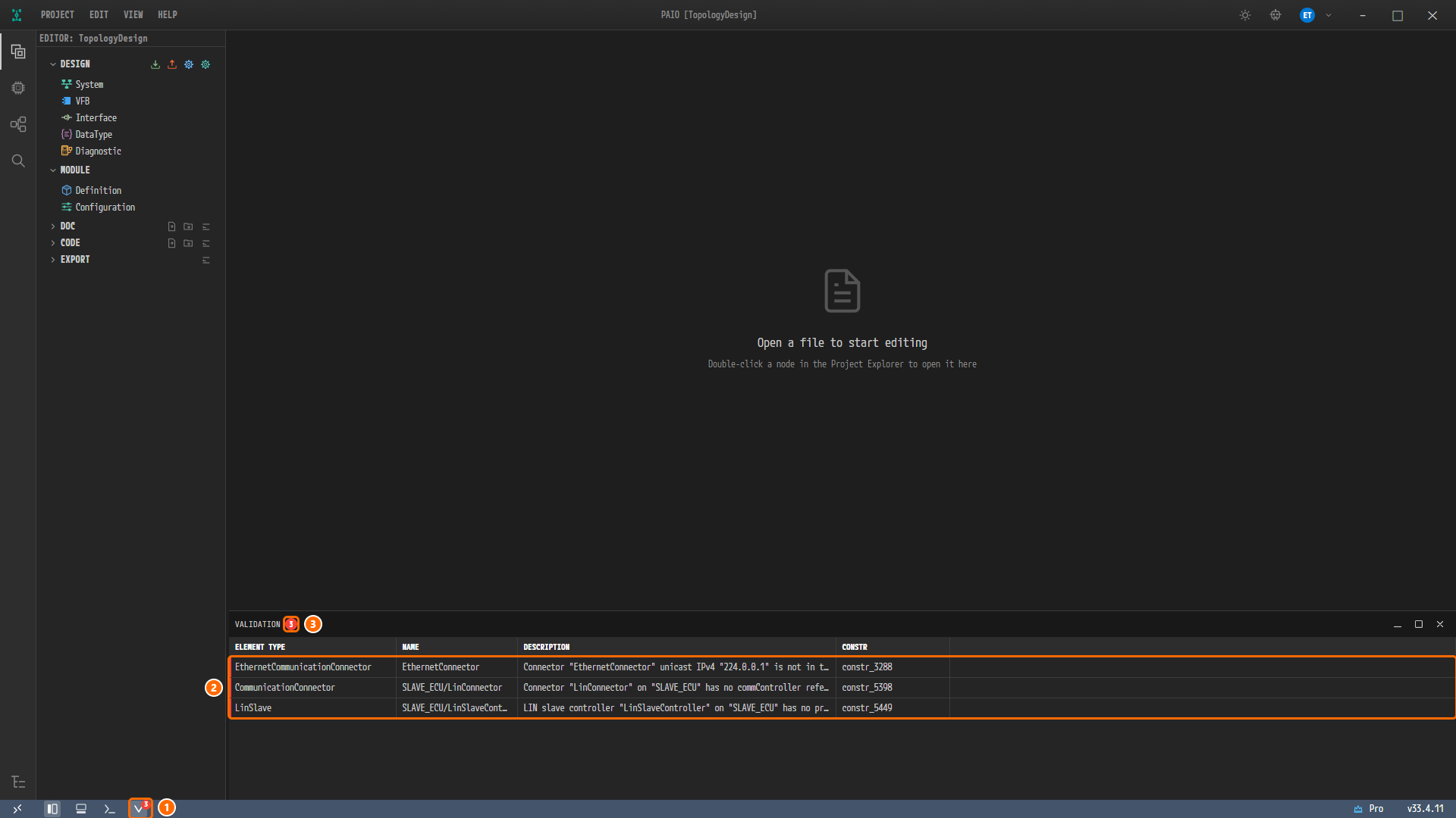
Figure 6-1. The screen after opening the panel. ① The V icon in the footer (badge
3), ② the three error rows, ③ the badge3next to the panel title VALIDATION. No editor is open, so the middle shows the empty editor area (Open a file to start editing). At the default column widths, NAME and DESCRIPTION are cut off with….
Reading the Columns
Each row of the panel is one error. The columns mean the following.
| Column | Content |
|---|---|
| ELEMENT TYPE | The kind of element that has the problem |
| NAME | The name of that element. Some rows put the node name in front, as in SLAVE_ECU/LinConnector |
| DESCRIPTION | A sentence explaining what is wrong |
| CONSTR | The AUTOSAR constraint number (constr_*) |
-
If the text is cut off, drag the right edge of the NAME and DESCRIPTION headers to the right to widen them. This step is optional. Once widened, all three sentences are shown in full.
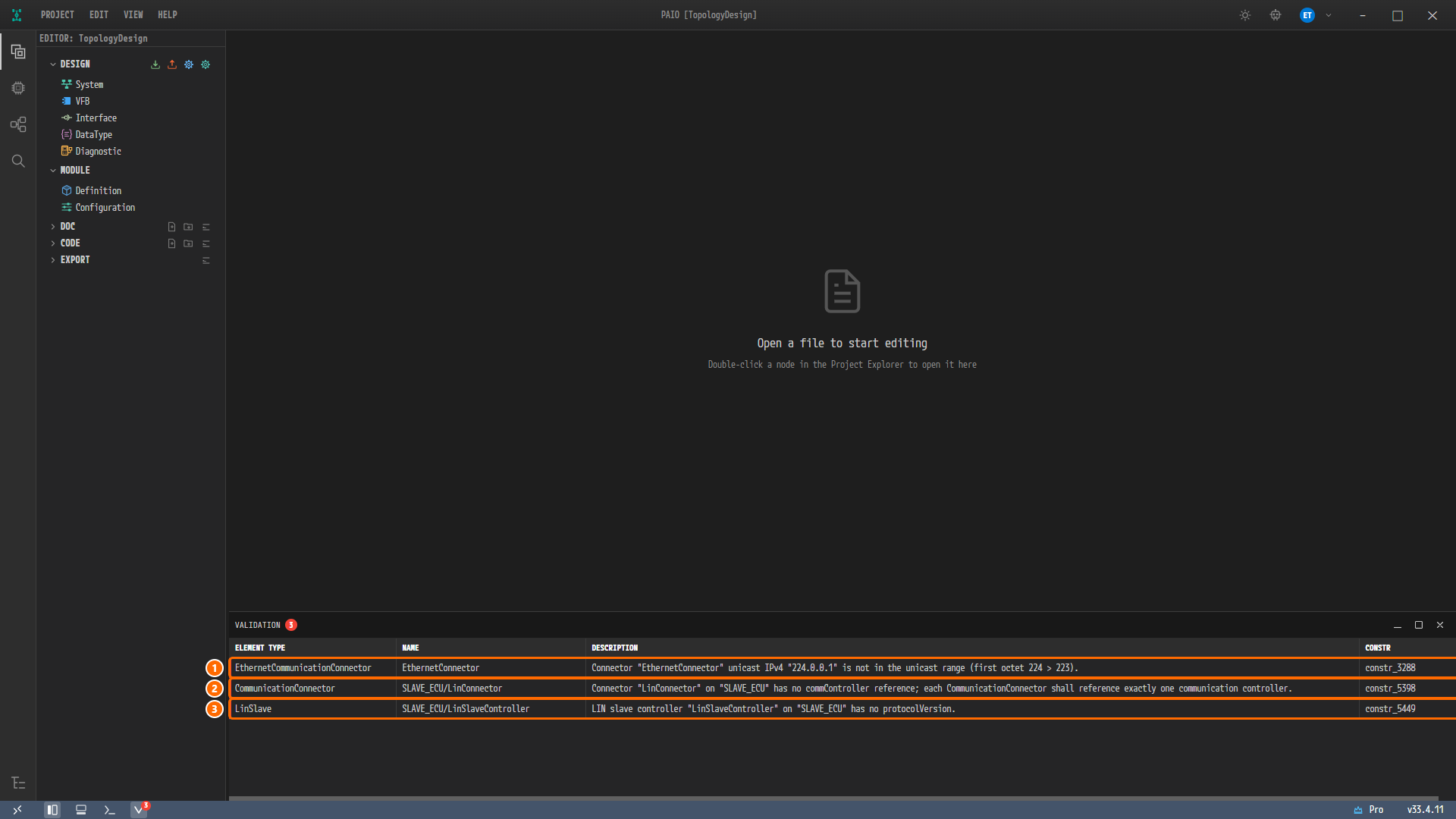
Figure 6-2. The VALIDATION panel with the NAME and DESCRIPTION columns widened. ① The
constr_3288row, ② theconstr_5398row, ③ theconstr_5449row.
The three rows, in panel order, are as follows. All of them are errors.
| # | ELEMENT TYPE | NAME | DESCRIPTION | CONSTR |
|---|---|---|---|---|
| 1 | EthernetCommunicationConnector | EthernetConnector | Connector "EthernetConnector" unicast IPv4 "224.0.0.1" is not in the unicast range (first octet 224 > 223). | constr_3288 |
| 2 | CommunicationConnector | SLAVE_ECU/LinConnector | Connector "LinConnector" on "SLAVE_ECU" has no commController reference; each CommunicationConnector shall reference exactly one communication controller. | constr_5398 |
| 3 | LinSlave | SLAVE_ECU/LinSlaveController | LIN slave controller "LinSlaveController" on "SLAVE_ECU" has no protocolVersion. | constr_5449 |
Note. A row moves you with a single click. Hovering over a row that can move you shows the tooltip
Go to the element to fix. Of the three rows of this chapter, only theconstr_5398row opens the property panel of the defective element directly. The other two rows get you close to it, and you then click the element to fix directly on the canvas.
Fixing the Unicast Address of the HPC Connector
Clicking the Row to Move to the System Editor
-
Click the first row (
constr_3288) of the VALIDATION panel. The System editor tabTopologyDesign:Systemopens, and the Ethernet connectorEthernetConnectorof the nodeZONEis selected. The property panel on the right has the title ETHERNET CONNECTOR, CONTROLLER isEthernetCommController, and UNICAST IPV4 ADDRESS is192.168.0.19. The VALIDATION panel stays open.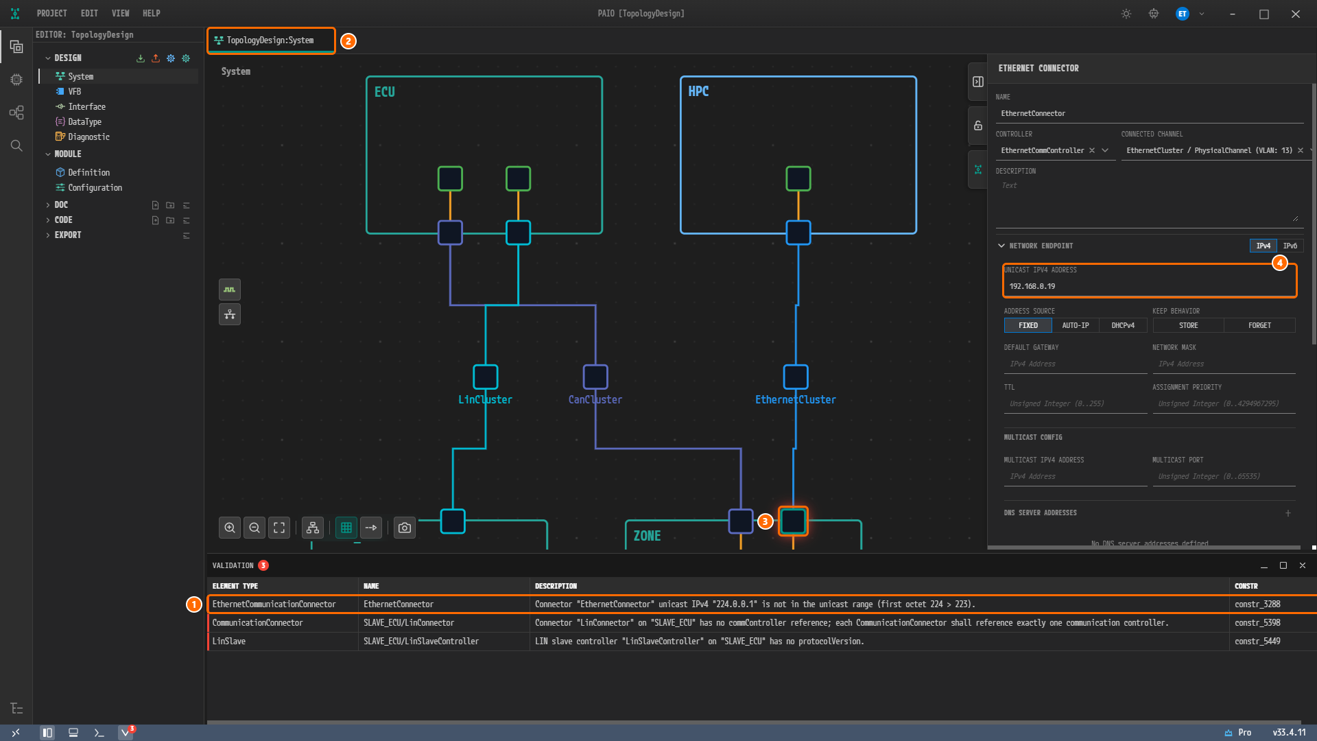
Figure 6-3. The result of clicking the first row. ① The
constr_3288row, ② the newly opened tabTopologyDesign:System, ③ the selected Ethernet connector ofZONE(bottom of the canvas), ④ UNICAST IPV4 ADDRESS =192.168.0.19. In the EDITOR view, System under DESIGN is highlighted.
Caution. This row moves you not to the defective connector of
HPCbut to the connector ofZONE. The Ethernet connectors of both nodes have the same nameEthernetConnector, and the row picks the one onZONE. The red validation mark on the canvas is also attached to the connector ofZONE. Do not change the values of theZONEconnector.
Selecting the HPC Connector
-
Click Fit to View in the toolbar below the canvas. All four nodes become visible.
-
Click the connector (
EthernetConnector) on the bottom edge of the nodeHPC. The panel title stays ETHERNET CONNECTOR, and CONTROLLER isEthernetController. UNICAST IPV4 ADDRESS and MULTICAST IPV4 ADDRESS are both224.0.0.1.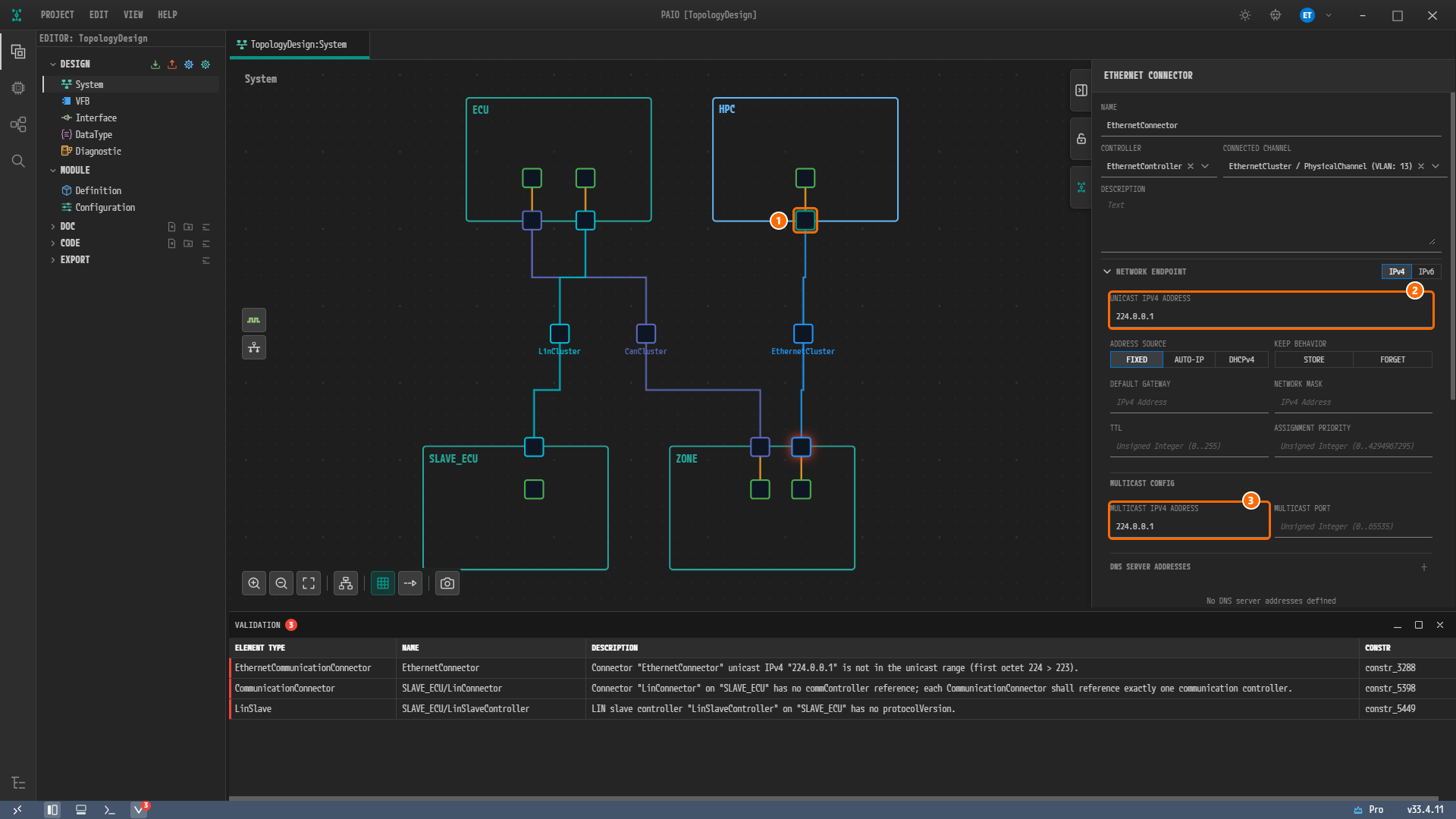
Figure 6-4. The screen with the connector of
HPCselected. ① The connector ofHPC, ② UNICAST IPV4 ADDRESS =224.0.0.1, ③ MULTICAST IPV4 ADDRESS =224.0.0.1. The red validation mark still remains on the right connector ofZONE.
Note. The UNICAST IPV4 ADDRESS field does not mark
224.0.0.1as an error. This defect shows only in the VALIDATION panel.
Entering 192.168.0.11
-
Delete
224.0.0.1in UNICAST IPV4 ADDRESS, type192.168.0.11and press theTabkey. Leave FIXED of ADDRESS SOURCE and MULTICAST IPV4 ADDRESS as they are. -
A blue dot (the modified mark) appears next to the name of the tab
TopologyDesign:System. Without saving, the VALIDATION panel immediately shrinks to two rows, and the badges next to the panel title and in the footer become2. The red mark on theZONEconnector also disappears.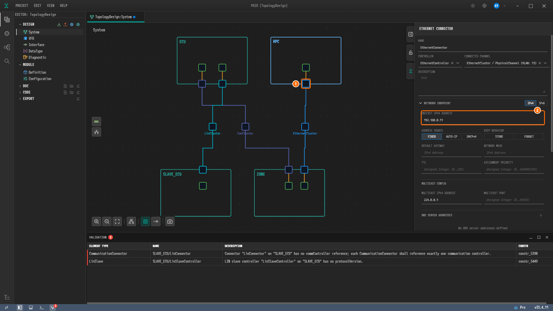
Figure 6-5. The screen after the fix. ① The connector of
HPC, ② UNICAST IPV4 ADDRESS =192.168.0.11. The VALIDATION panel keeps two rows, withoutconstr_3288.
Assigning a Controller to the SLAVE_ECU Connector
Selecting the Connector
-
Click the
constr_5398row (now the first row) of the VALIDATION panel. This time the row selects the defective element itself, the connector (LinConnector) on the top edge of the nodeSLAVE_ECU, so you do not need to click the canvas. -
Check the property panel. The panel title is LIN CONNECTOR, CONTROLLER shows the italic placeholder
Select controller..., and CONNECTED CHANNEL showsLinCluster / PhysicalChannel. CONTROLLER is a required field, so its label is red with the hintController is required. The canvas has no orange line joining this connector and the controller.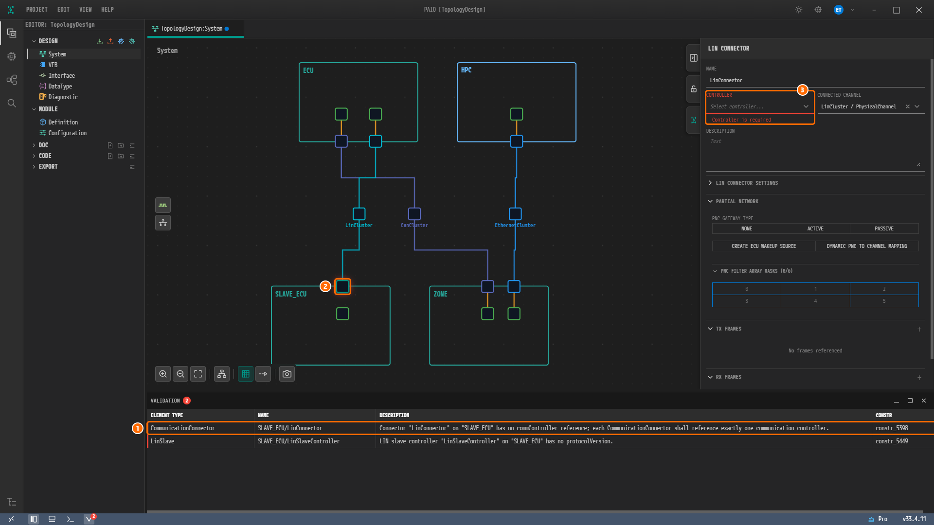
Figure 6-6. The result of clicking the
constr_5398row. ① Theconstr_5398row, ② the selected connector ofSLAVE_ECU, ③ CONTROLLER =Select controller..., red withController is required.
Choosing LinSlaveController
-
Click the CONTROLLER field. The field turns into a search box with the placeholder
Type to search..., and the list shows onlyLinSlaveController.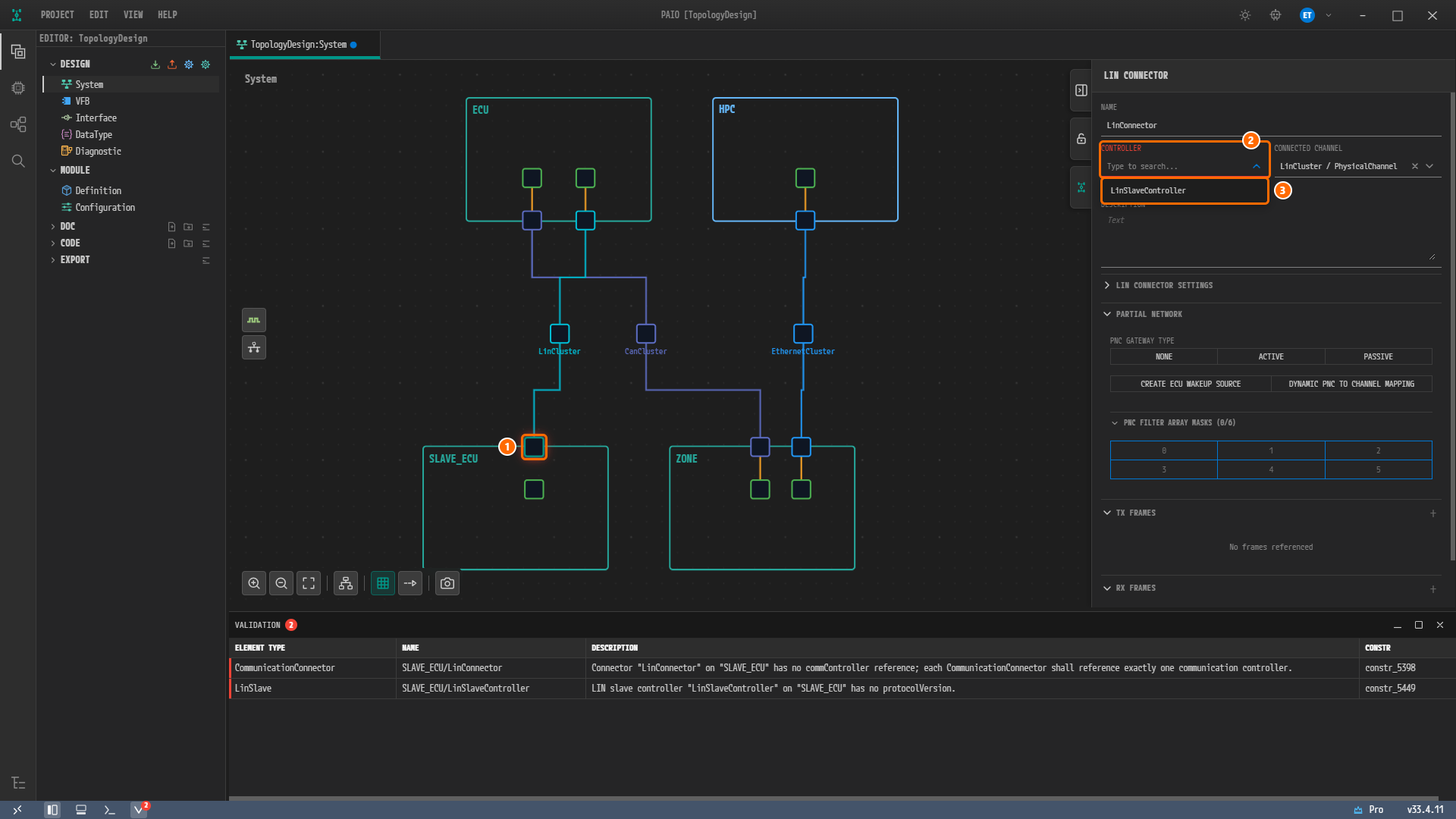
Figure 6-7. The open CONTROLLER list. ① The connector of
SLAVE_ECU, ② the CONTROLLER field (Type to search...), ③ the only itemLinSlaveController. -
Click
LinSlaveController. The VALIDATION panel shrinks to one row and the badge becomes1.
On the canvas, the orange line joining the connector and the controller appears again (Figure 6-9).
Choosing the Protocol Version of the LIN Slave Controller
Clicking the Row to Move to SLAVE_ECU
-
Click the
constr_5449row (now the only row). The nodeSLAVE_ECUis selected and the inside of the node is painted red. The panel title is ECU and NAME isSLAVE_ECU. This row picks not the controller but the node that holds the controller.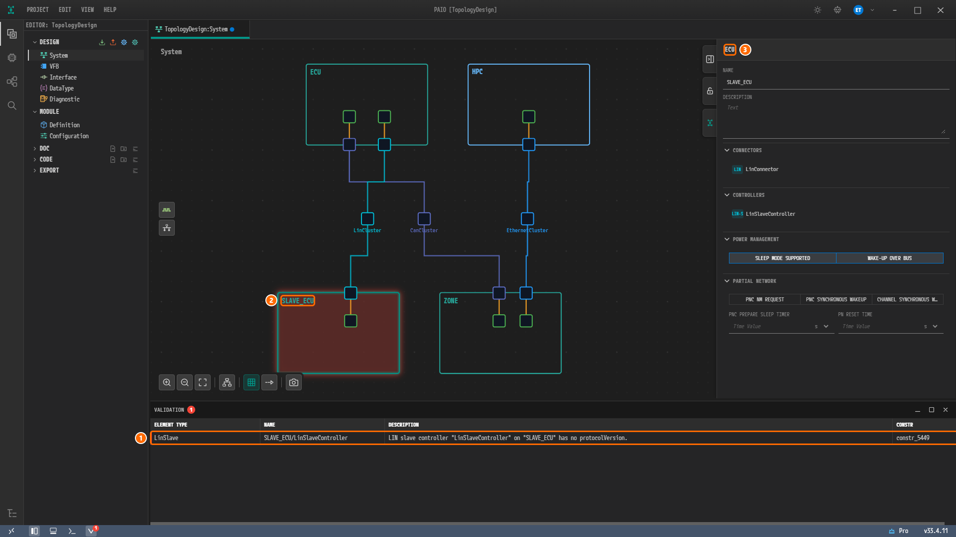
Figure 6-8. The result of clicking the
constr_5449row. ① Theconstr_5449row, ② the header of the nodeSLAVE_ECUmarked in red, ③ the panel title ECU. One row remains in the VALIDATION panel.
Choosing LIN 2.0
-
Click the controller square (
LinSlaveController) inside the nodeSLAVE_ECU. The panel title is LIN SLAVE, and PROTOCOL VERSION under LIN SETTINGS is a set of buttons,LIN 1.3,LIN 2.0,LIN 2.1,LIN 2.2andISO 17987, with no button on. Unlike CONTROLLER, this field is not marked in red. -
Under PROTOCOL VERSION, click
LIN 2.0. The button turns on, the last row disappears from the VALIDATION panel, and the panel showsNo validation issues.. The badges next to the panel title and on the V icon in the footer disappear.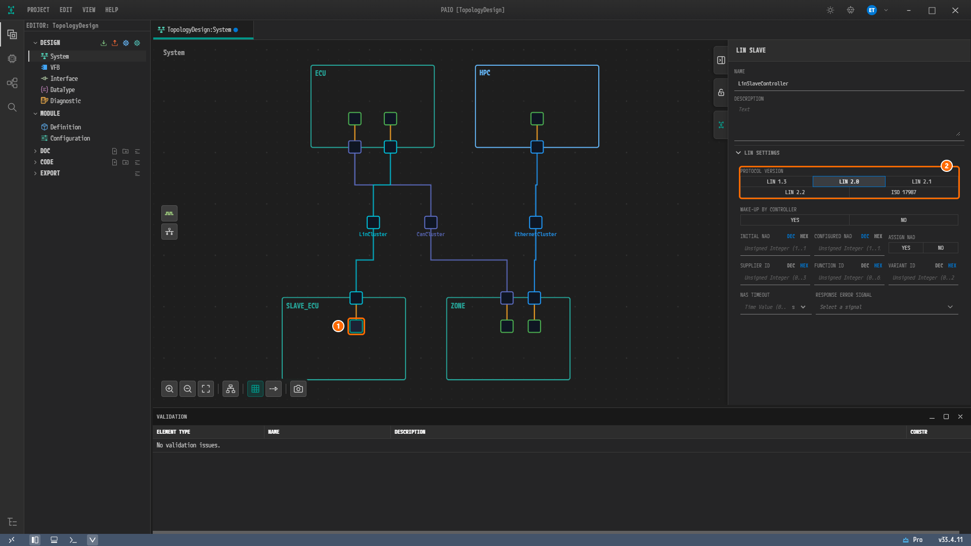
Figure 6-9. The screen after the fix. ① The controller square inside
SLAVE_ECU, ② PROTOCOL VERSION =LIN 2.0. The orange line between the connector and the controller shows again, and the VALIDATION panel showsNo validation issues..
What each of the three rows selects when clicked, and the element you actually fix, are summarized below.
| Row | Selected when clicked | Element to fix |
|---|---|---|
constr_3288 | The tab TopologyDesign:System opens with EthernetConnector of ZONE | Click EthernetConnector of HPC directly |
constr_5398 | LinConnector of SLAVE_ECU (panel LIN CONNECTOR) | The selected connector itself; no canvas click is needed |
constr_5449 | The node SLAVE_ECU (panel ECU) | Click LinSlaveController inside the node once more |
Saving and Validating Again
-
Click an empty spot of the canvas with no node. The property panel closes.
-
Press
Ctrl+Sto save. The blue dot on the tabTopologyDesign:Systemdisappears. -
Look at the VALIDATION panel, which stays open. It still shows
No validation issues., and there is no badge next to the panel title or on the V icon in the footer.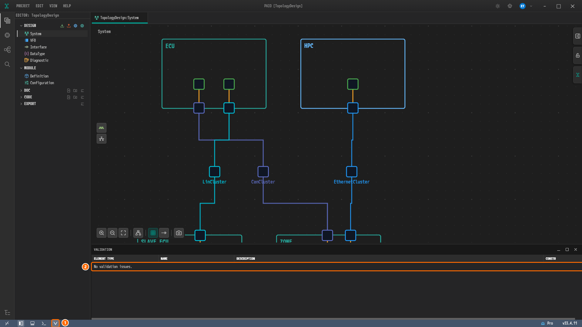
Figure 6-10. The screen after saving. ① The V icon in the footer with no badge, ② the row
No validation issues.. The property panel is closed.
Note. When you close the property panel by clicking an empty spot of the canvas, the canvas zoom returns to the zoom from before you clicked Fit to View (Figure 6-3). That is why
SLAVE_ECUandZONEat the bottom appear cut off above the VALIDATION panel in Figure 6-10. Only the screen zoom has changed, and the design is unchanged.Ctrl+Sdoes not change the zoom.
Note. The badge on the V icon disappears when the count drops to zero, but the tooltip of the V icon keeps the last count,
Validation: 1 error(s), 0 warning(s), 0 info(s). The VALIDATION panel shows the current result.
The panel is recalculated each time you fix a value, even without saving, so this step confirms that the result stays the same after saving. With each fix the badges drop as follows.
| After the fix | Rows left in the panel | Panel badge | Footer badge |
|---|---|---|---|
| Start | 3 | 3 | 3 |
HPC connector UNICAST IPV4 ADDRESS → 192.168.0.11 | 2 (constr_5398, constr_5449) | 2 | 2 |
SLAVE_ECU connector CONTROLLER → LinSlaveController | 1 (constr_5449) | 1 | 1 |
LinSlaveController PROTOCOL VERSION → LIN 2.0 | 0 (No validation issues.) | None | None |
Save with Ctrl+S | 0 (No validation issues.) | None | None |
With the three defects fixed, no rows remain. The three fixed values are the same as in the design finished in LIN Bus.
Why Is It Designed This Way?
- A unicast address is the address of a single node.
224.0.0.1is the multicast address used for SOME/IP service discovery (SD), which you entered into MULTICAST IPV4 ADDRESS in Ethernet Bus. A unicast address must have a first octet of 223 or less, so validation rejects this value withfirst octet 224 > 223. The own address ofHPCis192.168.0.11, theHPC_Endpointof the reference design. - A connector must refer to exactly one controller. In the words of the message,
each CommunicationConnector shall reference exactly one communication controller.. A connector attaches to the bus through its controller, so without a controller the orange line joining the two also disappears from the canvas. - A LIN controller needs a protocol version. The
LinSlaveControllerof the reference design has the protocol versionLIN20, andLIN 2.0of PROTOCOL VERSION corresponds to this value. "Values Not Entered in This Chapter" in LIN Bus explains this correspondence.
Checklist
- The VALIDATION panel shows
No validation issues.. - There is no badge next to the VALIDATION panel title or on the V icon in the footer.
- Selecting
EthernetConnectorofHPCshows UNICAST IPV4 ADDRESS192.168.0.11and MULTICAST IPV4 ADDRESS224.0.0.1. - UNICAST IPV4 ADDRESS of
EthernetConnectorofZONEis still192.168.0.19. - Selecting
LinConnectorofSLAVE_ECUshows CONTROLLERLinSlaveController, and the canvas has the orange line joining the connector and the controller. - Selecting
LinSlaveControllershows PROTOCOL VERSIONLIN 2.0. - The tab
TopologyDesign:Systemcarries no modified mark.
Next Step
In ARXML Export you export the fixed topology to ARXML files and compare them with the reference design.