LIN Bus
What You Will Do
In this chapter you join the nodes ECU and SLAVE_ECU with a LIN bus, in the System editor as you left it in Ethernet Bus.
You create the LIN master controller LinController_Master and the connector LinConnector_Master on ECU, and the LIN slave controller LinSlaveController and the connector LinConnector on SLAVE_ECU. On the master controller you enter the protocol version and the time base.
You then create the LIN cluster LinCluster from the + badge of the SLAVE_ECU connector and connect both connectors to the physical channel PhysicalChannel. The idle timeout 10 ms of the reference design is below the minimum the System editor accepts, so the channel keeps no idle timeout. A LIN cluster has no network management (NM), and its transport protocol (TP) is off for a new cluster, so in this chapter you do not open the cluster configuration window.
When you finish this chapter, the design in which LinCluster joins ECU and SLAVE_ECU is saved in the System editor, and the VALIDATION panel shows No validation issues..
Before You Begin
- Start after finishing Ethernet Bus.
ECUandZONEare joined byCanCluster,ZONEandHPCare joined byEthernetCluster, andSLAVE_ECUis still empty. The VALIDATION panel showsNo validation issues.. - If the tab
TopologyDesign:Systemis not open, click System under DESIGN in the EDITOR view. - If the VALIDATION panel is open, close it with the V icon in the footer. The figures show the screen with the panel closed.
- When you select an element, the property panel opens on the right and covers the right side of the canvas. If the node
HPCis hidden under the panel, click Fit to View in the toolbar below the canvas and then click Zoom Out a few times until all four nodes are visible. The figures in this chapter show the canvas zoomed out this way.
The values you enter in this chapter are listed below. The channel name PhysicalChannel is a default that is filled in automatically when the cluster is created, so you do not type it.
| Where | Item | Value |
|---|---|---|
LIN MASTER panel (node ECU) | NAME / PROTOCOL VERSION | LinController_Master / click LIN 2.0 |
LIN MASTER panel (node ECU) | TIME BASE / TIME BASE JITTER | 1 / 1 (unit ms) |
LIN SLAVE panel (node SLAVE_ECU) | NAME / PROTOCOL VERSION | LinSlaveController / click LIN 2.0 |
LIN CONNECTOR panel (node ECU) | NAME / CONTROLLER | LinConnector_Master / select LinController_Master |
LIN CONNECTOR panel (node SLAVE_ECU) | NAME / CONTROLLER | LinConnector / select LinSlaveController |
| LIN CLUSTER panel | NAME / IDLE TIMEOUT | LinCluster / 10 (unit ms), which is refused and not saved |
| LIN CLUSTER panel | PHYSICAL CHANNELS › CHANNEL NAME | PhysicalChannel (default, leave as is) |
Note. A field in the property panel commits its value only when you leave the field. All values in this chapter go into the property panel, so press the
Tabkey after entering each value.
Creating the LIN Controllers
Adding the Master Controller
-
On the canvas, right-click an empty spot inside the node
ECU. The menu shows Add Connector, Add Controller, Add Ethernet Switch, Add Gateway, SW Mapping, Extract ECU and Delete. -
Hover over Add Controller and click LIN Master in the submenu.
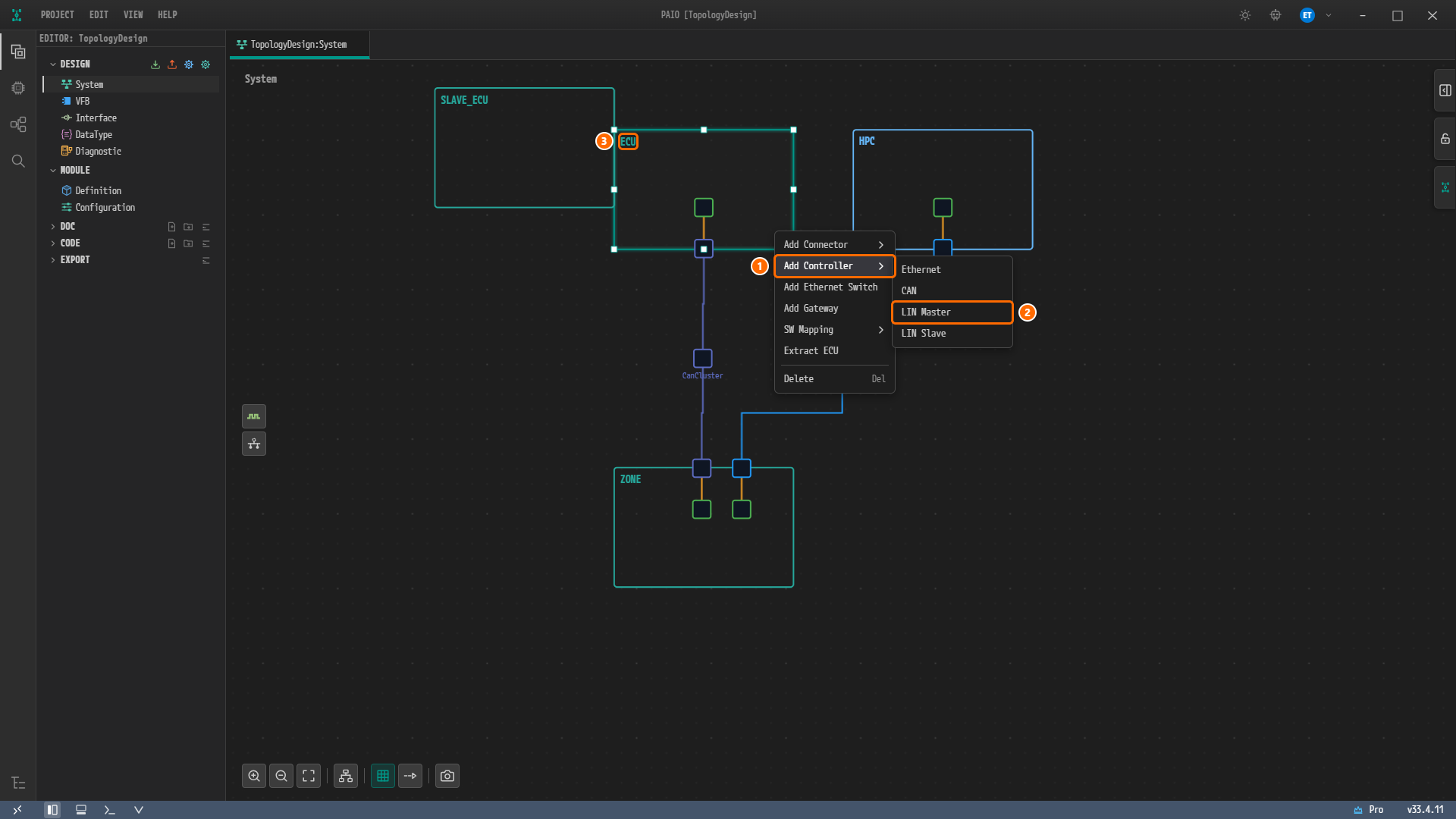
Figure 5-1. The context menu of the node
ECU. ① Add Controller, ② LIN Master in the submenu, ③ the right-clicked nodeECU. The submenu of Add Controller holds Ethernet, CAN, LIN Master and LIN Slave. -
A small square appears inside the node. This is the LIN master controller. The new controller is not selected automatically, so click the square. The property panel on the right is titled LIN MASTER, and NAME holds the default name
ECU_LinMaster_Controller_0.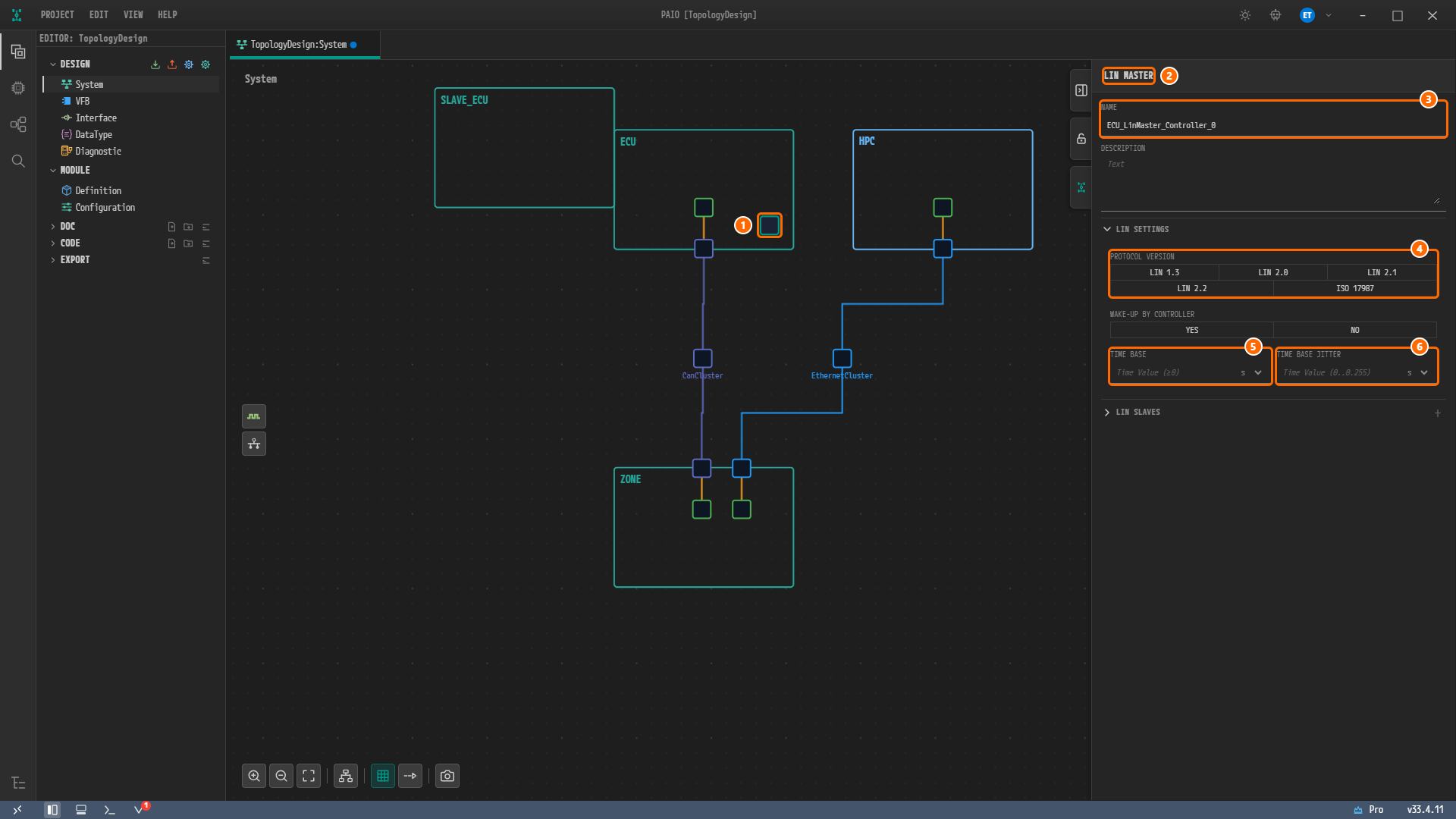
Figure 5-2. The new LIN master controller. ① The controller inside the node, ② the panel title LIN MASTER, ③ NAME =
ECU_LinMaster_Controller_0, ④ PROTOCOL VERSION with no button on, ⑤ the empty TIME BASE, ⑥ the empty TIME BASE JITTER. The V icon in the footer shows the red badge1.
The LIN MASTER panel holds NAME and DESCRIPTION, and below them the LIN SETTINGS section with PROTOCOL VERSION, WAKE-UP BY CONTROLLER (YES / NO), TIME BASE and TIME BASE JITTER. The LIN SLAVES section at the bottom is collapsed and has a + on the right. You do not expand LIN SLAVES in this chapter, and you do not click WAKE-UP BY CONTROLLER. The red badge 1 on the V icon is the validation error constr_5449 (LIN master controller "ECU_LinMaster_Controller_0" on "ECU" has no protocolVersion.): a LIN controller needs a protocol version. The badge disappears when you click LIN 2.0 in the next section.
Entering the Name, Protocol Version and Time Base
-
Clear
ECU_LinMaster_Controller_0in the NAME field, typeLinController_Masterand press theTabkey. -
Under PROTOCOL VERSION, click
LIN 2.0. The buttons areLIN 1.3,LIN 2.0,LIN 2.1,LIN 2.2andISO 17987. The red badge on the V icon disappears. -
Change the unit box to the right of TIME BASE from
stoms. The unit list holdsns,us,msands. Then type1in the number field and press theTabkey. The empty field shows the hintTime Value (≥0). -
In the same way, change the unit of TIME BASE JITTER to
ms, type1and press theTabkey. Its empty field shows the hintTime Value (0..0.255).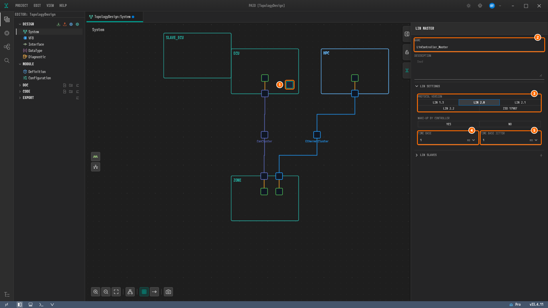
Figure 5-3. After entering the values. ① The controller, ② NAME =
LinController_Master, ③ PROTOCOL VERSION =LIN 2.0, ④ TIME BASE =1ms, ⑤ TIME BASE JITTER =1ms. WAKE-UP BY CONTROLLER stays unset, and the V icon has no badge.
Caution. The unit box defaults to
s. If you type1without changing the unit, the value is one second. If you type the number first and then change the unit, the displayed number may be recalculated for the new unit, so change the unit tomsfirst and then type the number.
Note.
1msis saved as0.001, a value in seconds. TheLinController_Masterof the reference design also has a time base and a jitter of0.001seconds each.
Creating the Slave Controller on SLAVE_ECU
-
Right-click an empty spot inside the node
SLAVE_ECU. -
Hover over Add Controller and click LIN Slave in the submenu.
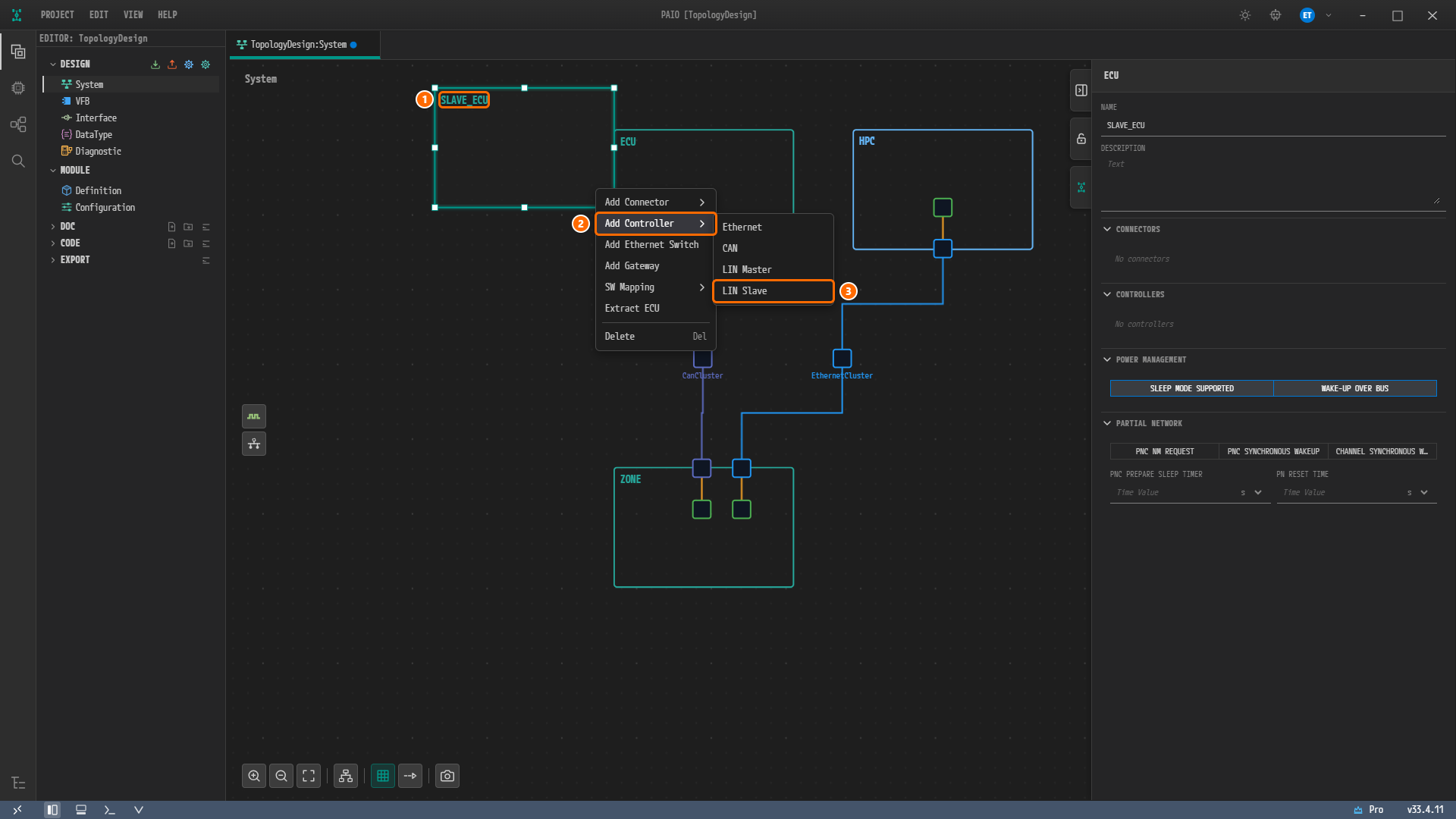
Figure 5-4. The context menu of the node
SLAVE_ECU. ① The right-clicked nodeSLAVE_ECU, ② Add Controller, ③ LIN Slave in the submenu. Right-clicking selects the nodeSLAVE_ECU, so the panel now shows the ECU panel with NAMESLAVE_ECU. -
A controller square appears inside
SLAVE_ECU. Click it; the panel is titled LIN SLAVE, and NAME holdsSLAVE_ECU_LinSlave_Controller_0. -
Type
LinSlaveControllerin NAME and press theTabkey. -
Under PROTOCOL VERSION, click
LIN 2.0. Leave everything below it as it is.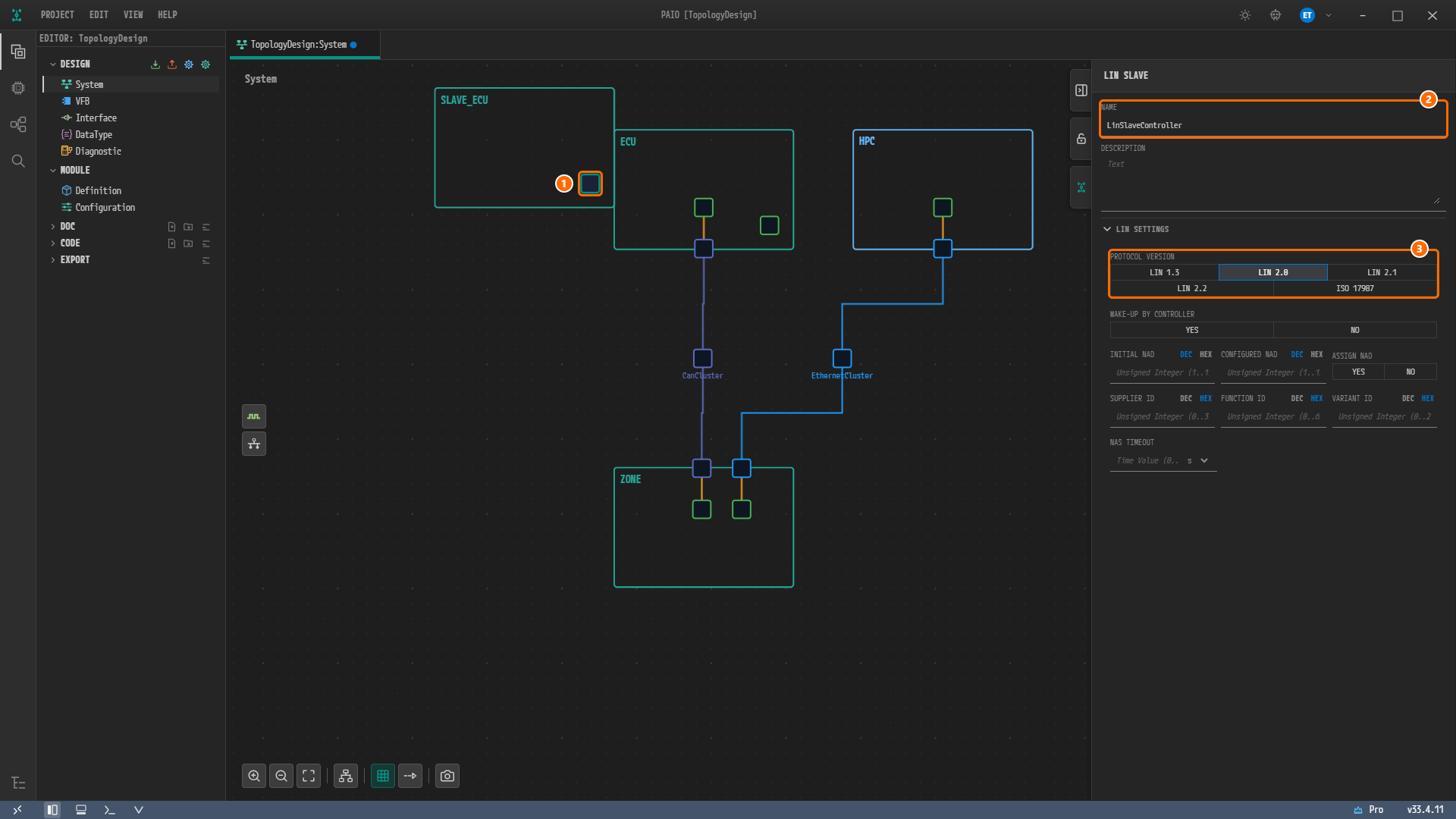
Figure 5-5. The LIN slave controller of the node
SLAVE_ECU. ① The controller insideSLAVE_ECU, ② NAME =LinSlaveController, ③ PROTOCOL VERSION =LIN 2.0.
Below PROTOCOL VERSION, the LIN SETTINGS section of the LIN SLAVE panel holds WAKE-UP BY CONTROLLER, INITIAL NAD, CONFIGURED NAD, ASSIGN NAD, SUPPLIER ID, FUNCTION ID, VARIANT ID and NAS TIMEOUT. TIME BASE and TIME BASE JITTER exist only in the master panel, not in the slave panel. This chapter uses only NAME and PROTOCOL VERSION.
The values of the two controllers are summarized below.
| Node | Menu | Default name | NAME | PROTOCOL VERSION | TIME BASE / TIME BASE JITTER |
|---|---|---|---|---|---|
ECU | Add Controller › LIN Master | ECU_LinMaster_Controller_0 | LinController_Master | LIN 2.0 | 1 ms / 1 ms |
SLAVE_ECU | Add Controller › LIN Slave | SLAVE_ECU_LinSlave_Controller_0 | LinSlaveController | LIN 2.0 | No fields |
Creating the LIN Connectors
Adding a Connector
-
Right-click an empty spot inside the node
ECU. -
Hover over Add Connector and click LIN in the submenu. The submenu holds Ethernet, CAN and LIN.
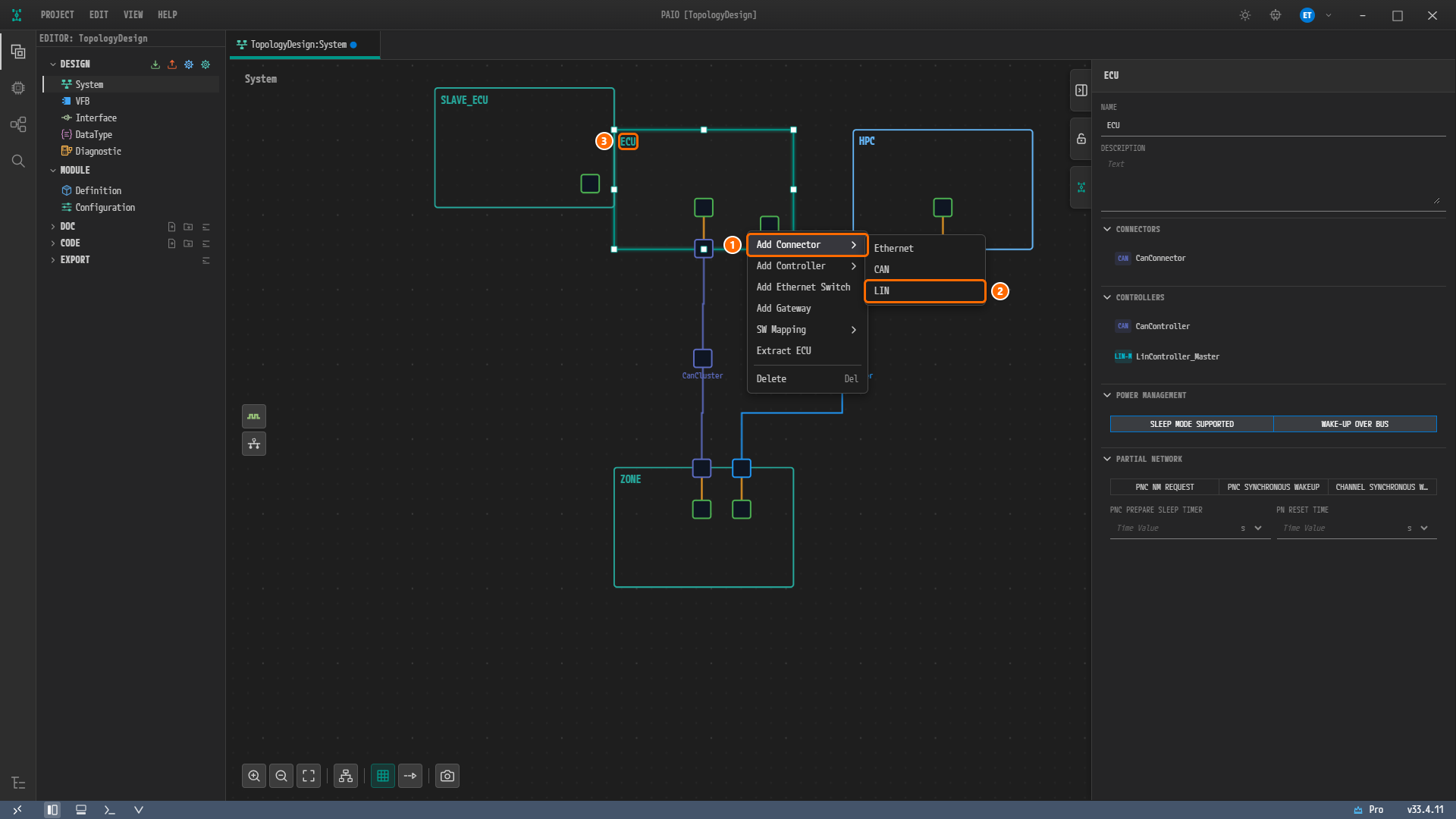
Figure 5-6. The context menu of the node
ECU. ① Add Connector, ② LIN in the submenu, ③ the right-clicked nodeECU. Right-clicking selects the nodeECU, so the panel now shows the ECU panel: CONNECTORS listsCanConnector, and CONTROLLERS listsCanControllerandLinController_Master. -
A connector square appears on the bottom edge of the node
ECU, to the right ofCanConnector, with a green + badge below it. The connector is not selected automatically either, so click the connector square. The panel is titled LIN CONNECTOR, NAME holdsECU_Lin_Connector_0, CONTROLLER showsSelect controller...and CONNECTED CHANNEL shows(None). CONTROLLER is a required field: while it is empty, its label is red with the hintController is required, and the V icon in the footer shows the red badge1.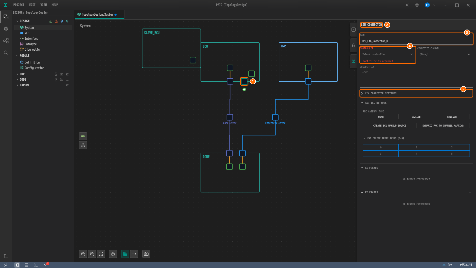
Figure 5-7. The new LIN connector. ① The connector on the bottom edge of the node, ② the panel title LIN CONNECTOR, ③ NAME =
ECU_Lin_Connector_0, ④ CONTROLLER =Select controller..., red withController is required, ⑤ the collapsed LIN CONNECTOR SETTINGS header. The V icon in the footer shows the badge1.
The LIN CONNECTOR panel holds NAME, CONTROLLER, CONNECTED CHANNEL and DESCRIPTION, followed by the sections LIN CONNECTOR SETTINGS, PARTIAL NETWORK, TX FRAMES and RX FRAMES. Unlike an Ethernet connector, it has no address fields. The collapsed LIN CONNECTOR SETTINGS section holds INITIAL NAD and SCHEDULE CHANGE NEXT TIME BASE. This chapter uses only NAME and CONTROLLER.
Setting the Name and Controller
-
Type
LinConnector_Masterin NAME and press theTabkey. -
Click the CONTROLLER field and click
LinController_Masterin the list. The list holds only the LIN controller of the same node,LinController_Master; theCanControllerof the same node does not appear. The red mark of CONTROLLER and the badge on the V icon disappear.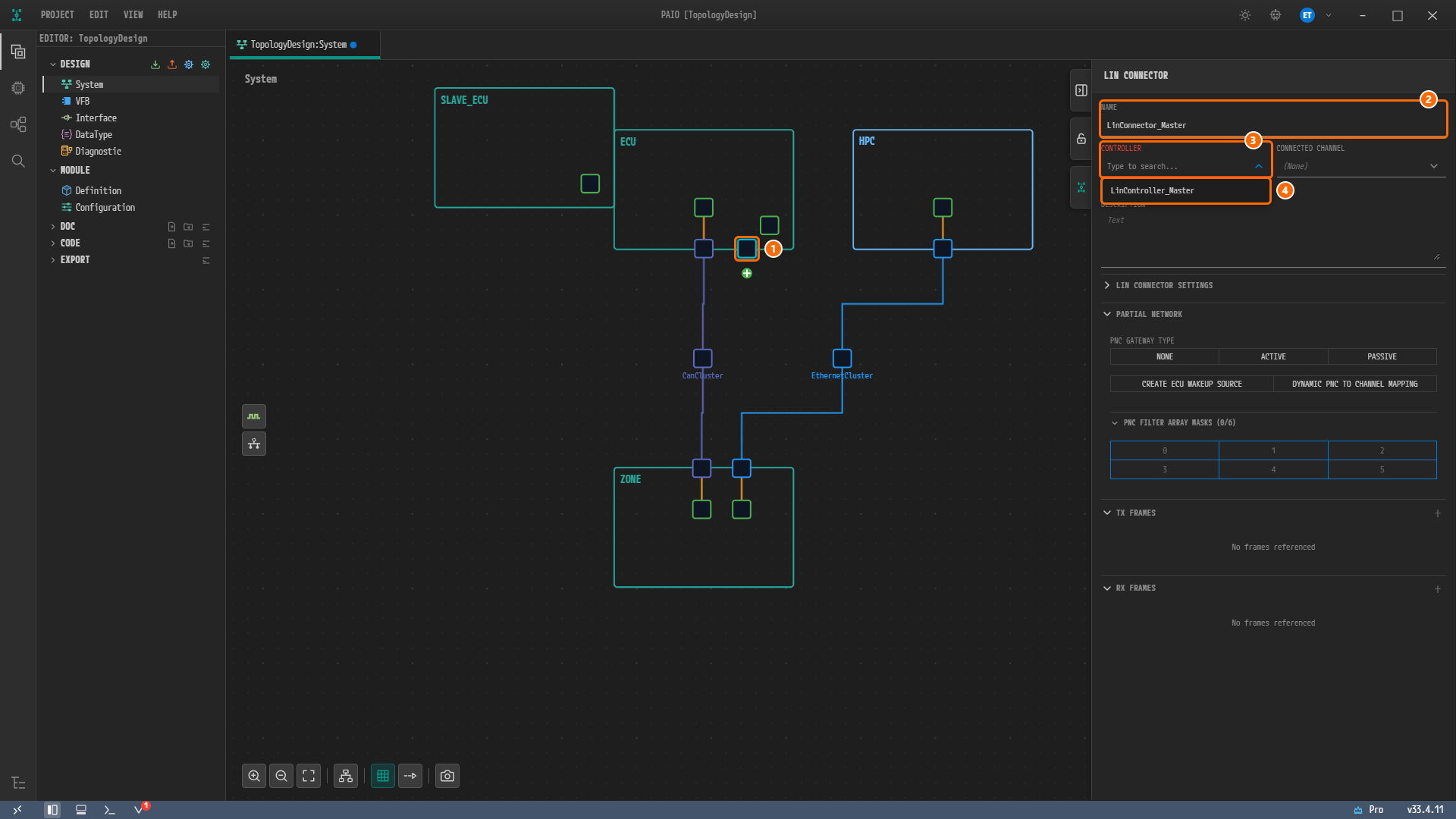
Figure 5-8. The CONTROLLER list. ① The connector, ② NAME =
LinConnector_Master, ③ the CONTROLLER field, still red because no controller is selected yet, ④LinController_Master, the only item in the list.
Note. The connector menu has a single LIN item with no master or slave distinction. Whether a connector is on the master side or the slave side is decided by the controller you choose in CONTROLLER.
Creating a Connector on SLAVE_ECU
-
Right-click an empty spot inside the node
SLAVE_ECUand click Add Connector › LIN. A connector square appears on the bottom edge ofSLAVE_ECU. Click it; the LIN CONNECTOR panel shows NAMESLAVE_ECU_Lin_Connector_0. -
Type
LinConnectorin NAME and press theTabkey. -
Click
LinSlaveControllerin the CONTROLLER list. It is the only item in the list. An orange line joining the connector and the controller appears on the canvas.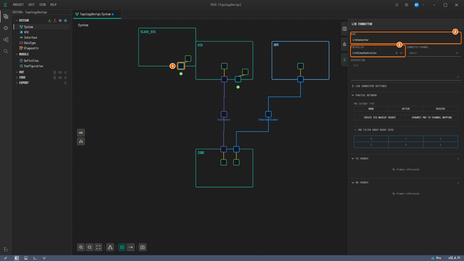
Figure 5-9. The LIN connector of the node
SLAVE_ECU. ① The connector ofSLAVE_ECU, ② NAME =LinConnector, ③ CONTROLLER =LinSlaveController.
The values of the two connectors are summarized below.
| Node | Default name | NAME | CONTROLLER |
|---|---|---|---|
ECU | ECU_Lin_Connector_0 | LinConnector_Master | LinController_Master |
SLAVE_ECU | SLAVE_ECU_Lin_Connector_0 | LinConnector | LinSlaveController |
Creating the LIN Cluster
Creating the Cluster from the SLAVE_ECU Connector
The connector on the side where you create the cluster becomes the first connector of the channel. To match the order of the reference design (SLAVE_ECU, ECU), you create the cluster from the connector of SLAVE_ECU.
-
Click the green + badge below the
LinConnectorof the nodeSLAVE_ECU. -
Click Create CommunicationCluster [Lin] in the menu that opens. It is the only item in the menu.
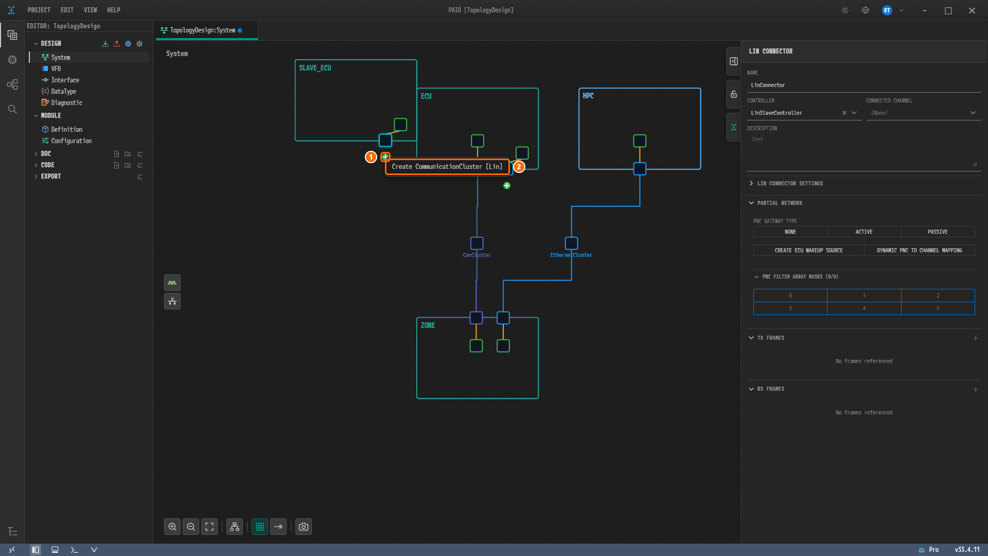
Figure 5-10. The + badge menu of the
SLAVE_ECUconnector. ① The + badge, ② Create CommunicationCluster [Lin]. -
A cluster square appears below the connector of
SLAVE_ECU, with its nameLinCluster_0written under it. If it is not visible, click Fit to View, and ifHPCis hidden under the panel, click Zoom Out. -
Click the cluster square. The panel is titled LIN CLUSTER, and NAME holds
LinCluster_0.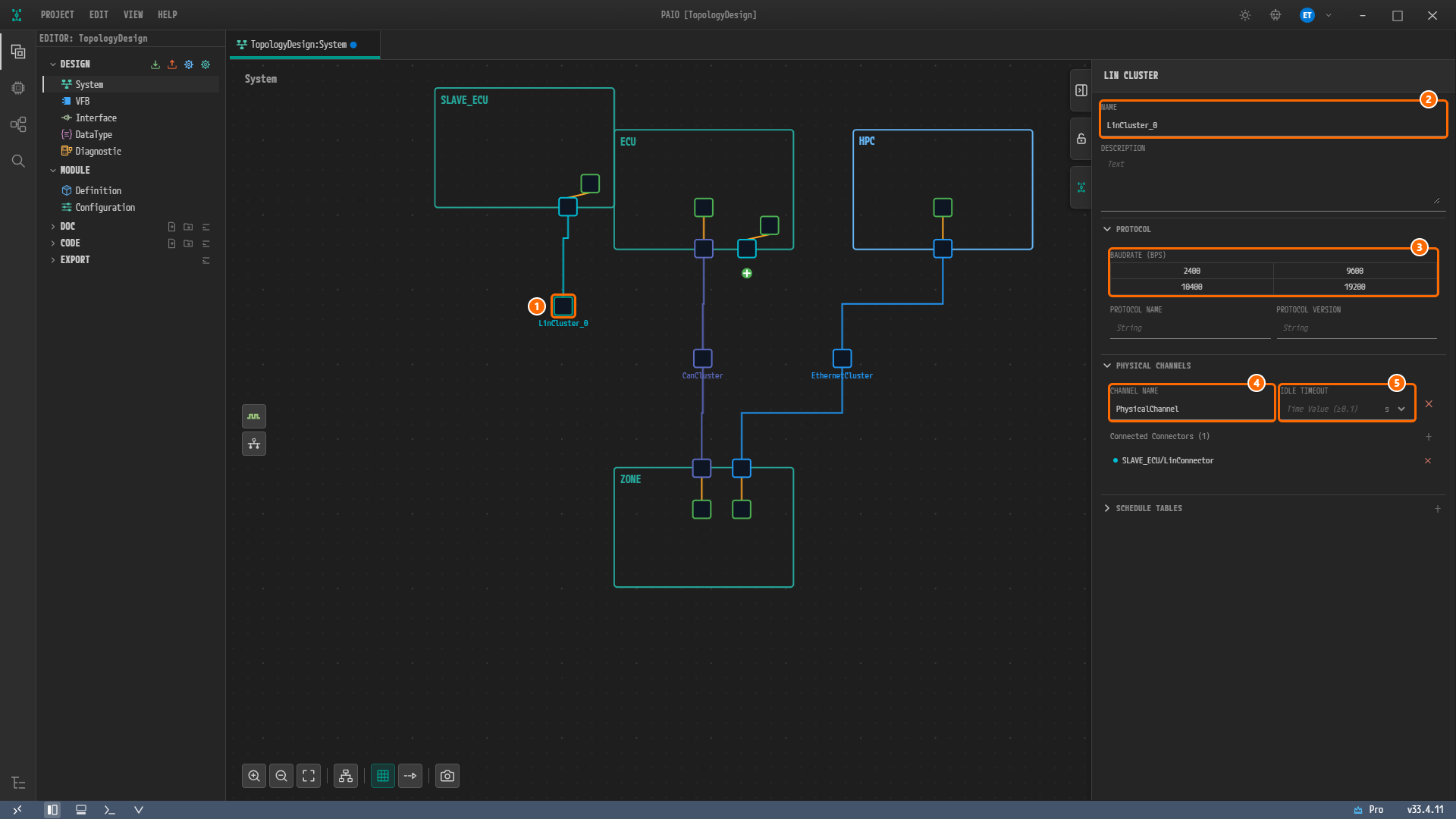
Figure 5-11. The new LIN cluster. ① The cluster square, ② NAME =
LinCluster_0, ③ PROTOCOL › BAUDRATE (BPS), where none of the buttons2400,9600,10400and19200is on, ④ CHANNEL NAME holding the defaultPhysicalChannel, ⑤ the empty IDLE TIMEOUT showing the hintTime Value (≥0.1).SLAVE_ECU/LinConnectorappears under Connected Connectors (1). -
Type
LinClusterin NAME and press theTabkey. The name under the square changes toLinCluster. -
Enter the idle timeout of the reference design to see the limit of the field: change the unit box to the right of IDLE TIMEOUT from
stoms, type10in the number field and press theTabkey. The field turns red and showsMust be at least 0.1, and the value is not saved. Leave BAUDRATE (BPS), PROTOCOL NAME, PROTOCOL VERSION and CHANNEL NAME as they are.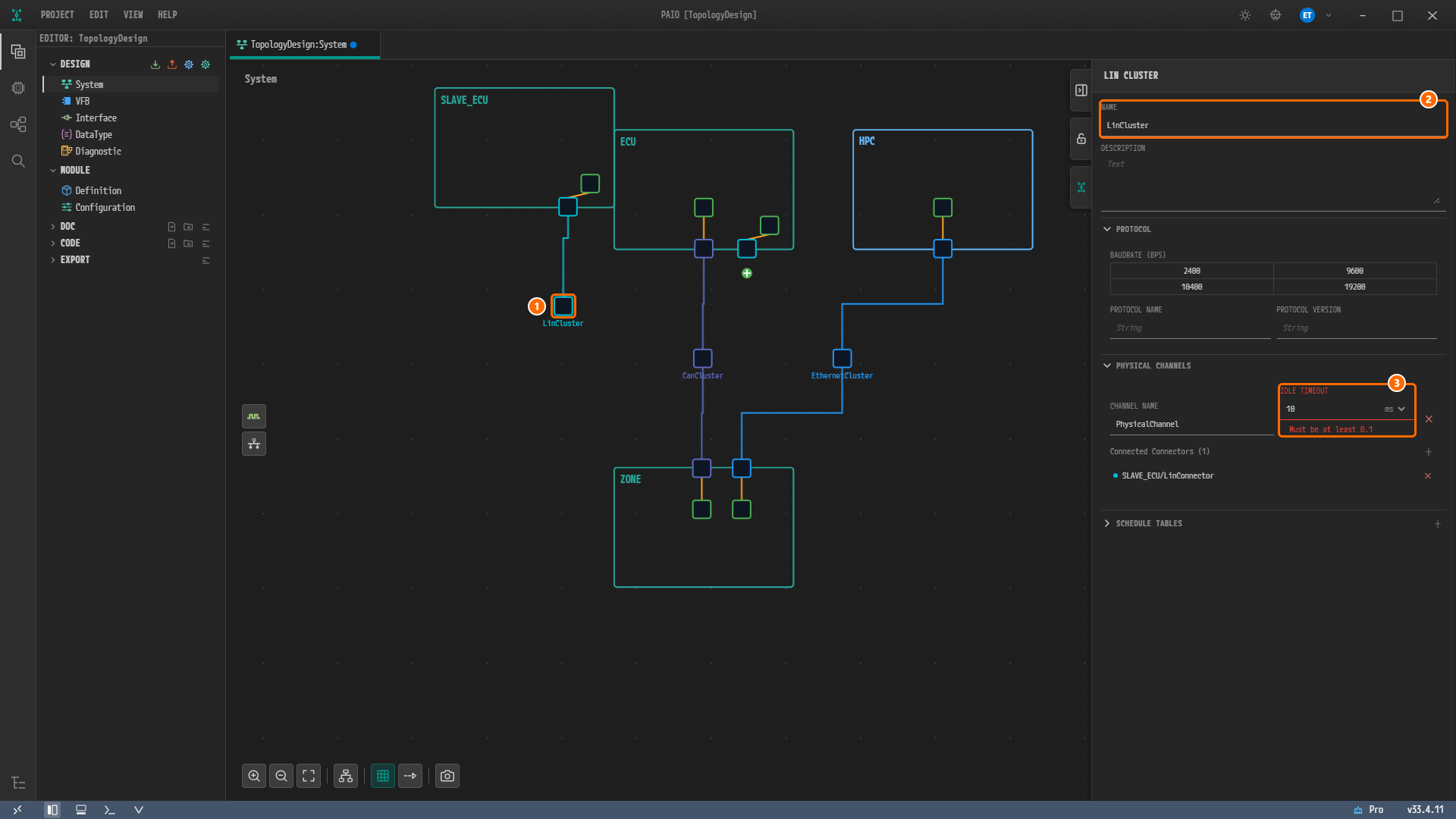
Figure 5-12. After entering the values. ① The cluster square with
LinClusterunder it, ② NAME =LinCluster, ③ IDLE TIMEOUT with10mstyped, red withMust be at least 0.1.
IDLE TIMEOUT is the time before the bus goes into the idle state. The field accepts only values of 0.1 seconds or more, so the value 0.01 seconds (10 ms) on the channel of the reference design cannot be entered, and the channel of this tutorial keeps no idle timeout. If the field accepts 10 without turning red, the unit box was still s: delete the number and press the Tab key so that the field is empty. Leave the SCHEDULE TABLES section at the bottom of the panel alone.
Note. None of the buttons of BAUDRATE (BPS) is on, even after you save and select the cluster again, but the saved cluster holds the baud rate
19200. The cluster of the reference design has no baud rate. The difference in the export result is covered in ARXML Export.
Connecting the ECU Connector to the Channel
-
Click the green + badge below the
LinConnector_Masterof the nodeECU. This time the menu holds Create CommunicationCluster [Lin] and Connect to Channel.... -
Hover over Connect to Channel..., hover over LinCluster in the submenu, and click PhysicalChannel in its submenu.
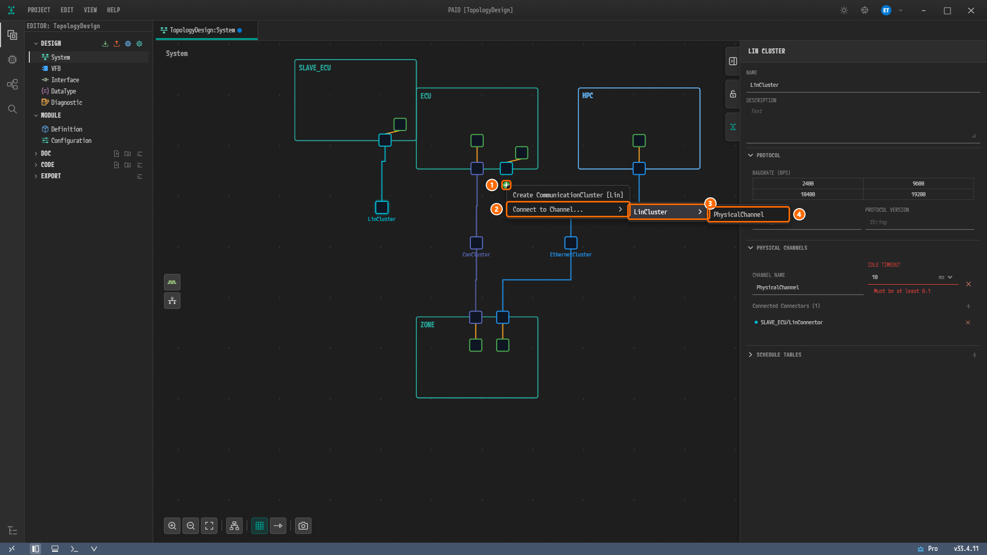
Figure 5-13. The + badge menu of the
ECUconnector. ① The + badge, ② Connect to Channel..., ③ LinCluster, ④ PhysicalChannel. The panel still shows the refused IDLE TIMEOUT input of Figure 5-12; it is not saved.
Caution. Create CommunicationCluster [Lin] in this menu creates a new cluster. Connect the connector of
ECUto the channel created earlier with Connect to Channel....
Tidying the Layout and Saving
-
Click Auto Layout in the toolbar below the canvas, then click Fit to View. If
HPCis hidden under the panel, click Zoom Out. -
Click the LIN cluster square and check that IDLE TIMEOUT is empty, showing the hint
Time Value (≥0.1), and thatSLAVE_ECU/LinConnectorandECU/LinConnector_Masterappear under Connected Connectors (2).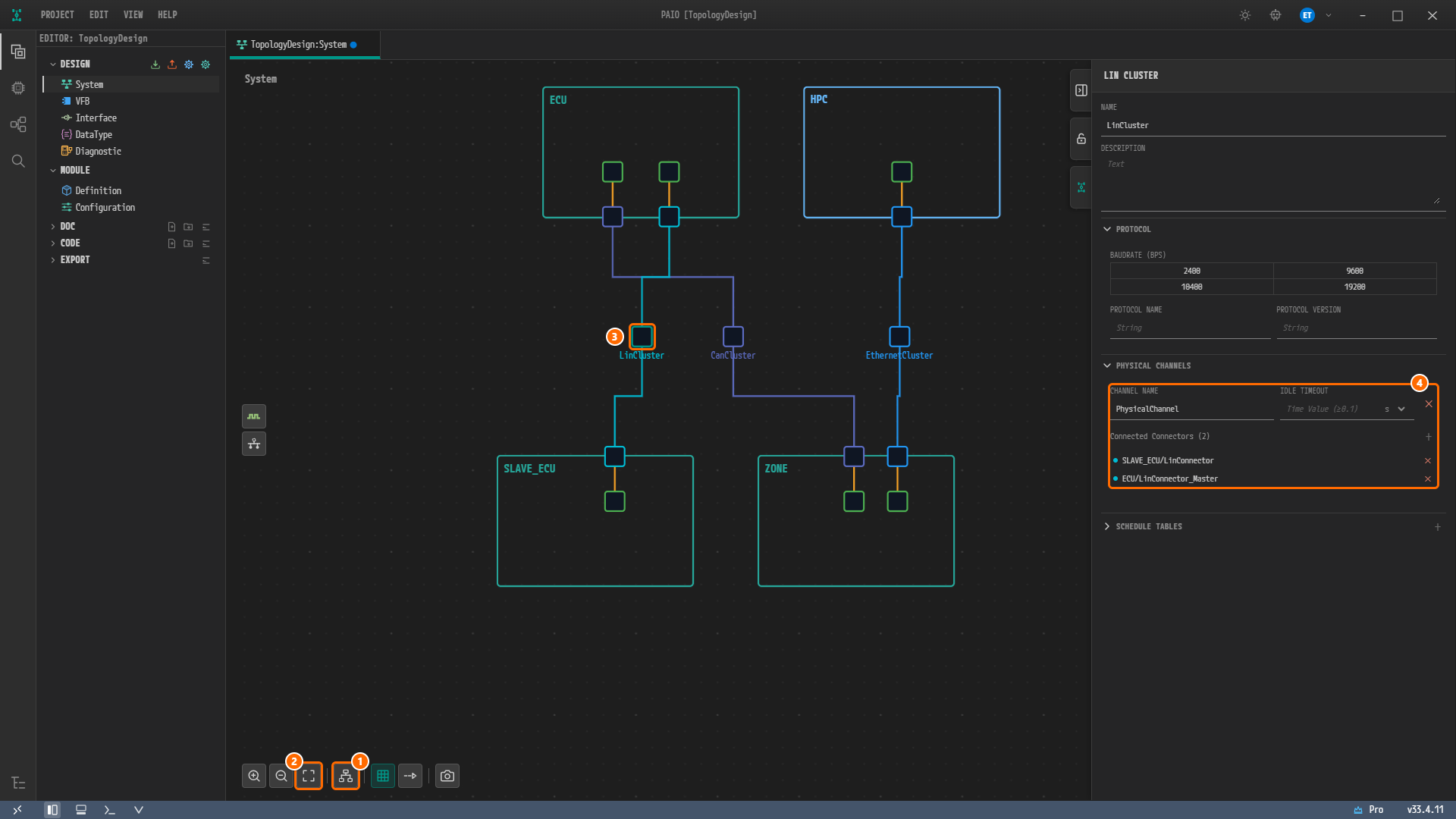
Figure 5-14. The canvas after Auto Layout. ① Auto Layout, ② Fit to View, ③ the LIN cluster square, ④ CHANNEL NAME
PhysicalChannel, the empty IDLE TIMEOUT andSLAVE_ECU/LinConnector,ECU/LinConnector_Masterunder Connected Connectors (2). The nodes are placed withECUandHPCat the top andSLAVE_ECUandZONEat the bottom. -
Click an empty spot of the canvas with no node, then press
Ctrl+Sto save. The blue dot on the tabTopologyDesign:Systemdisappears.
After connecting, CONNECTED CHANNEL of both connectors shows LinCluster / PhysicalChannel. The layout after Auto Layout may differ slightly from the figure, and the CAN line and the LIN line running down from ECU may appear to overlap over one stretch. This is a result of the layout and not an error, so you do not need to move the nodes.
Viewing the Validation Result
-
Click the V icon in the footer to open the VALIDATION panel.
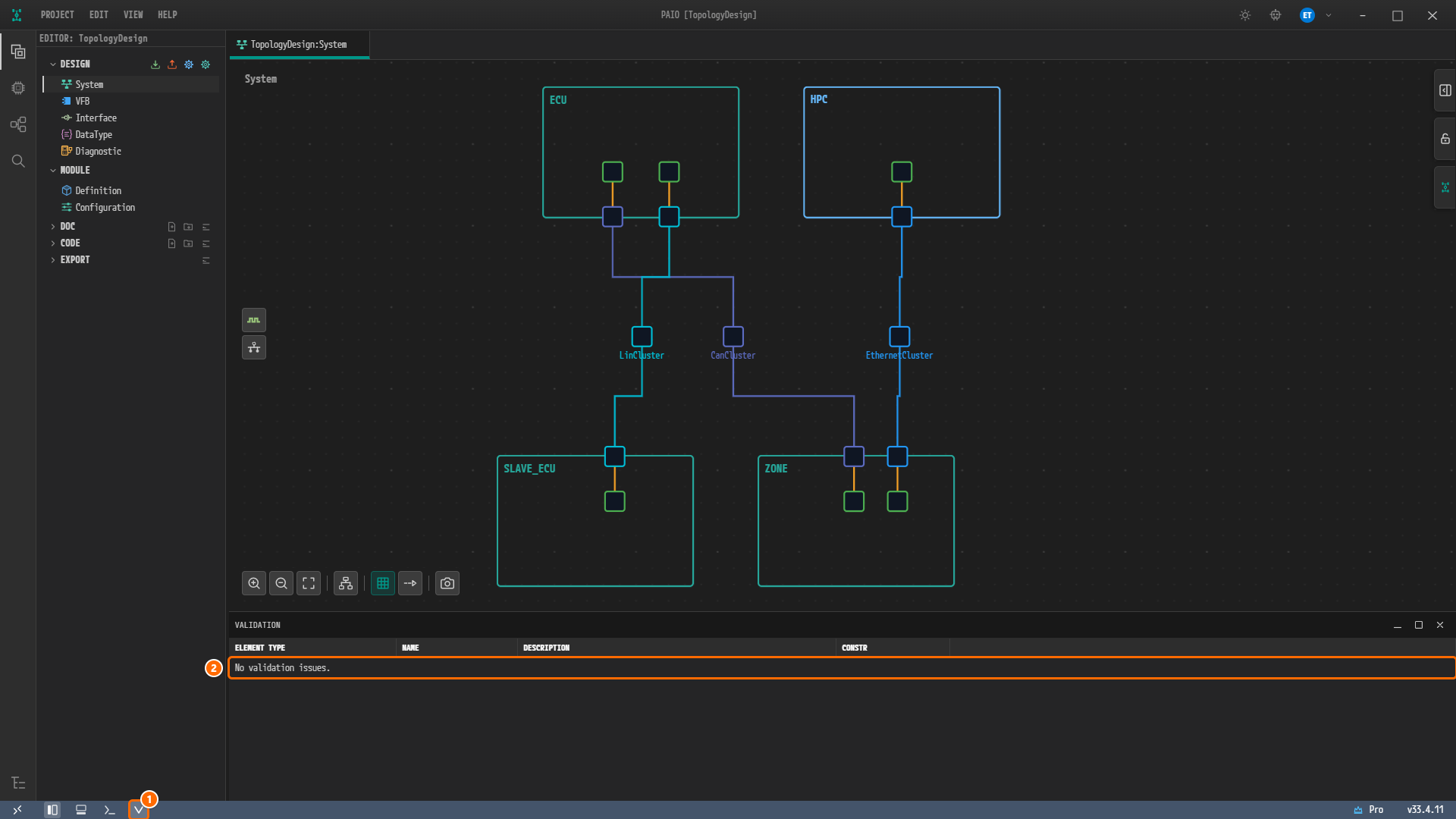
Figure 5-15. The VALIDATION panel after saving. ① The V icon in the footer, ② the row
No validation issues..
The validation result is zero findings, the same as at the end of Ethernet Bus. Adding the LIN bus brings no errors, and this result is expected.
- No NM cluster is created. Network management (NM) does not apply to a LIN cluster. The Communication Cluster Configuration window of a LIN cluster has only the CLUSTER and TRANSPORT PROTOCOL tabs, with no NM CLUSTER tab.
- No LIN TP configuration is created. The transport protocol (TP) is off for a new cluster, as it was for
CanClusterin CAN Bus, and this tutorial leaves it off. The reference design has no TP configuration either.
Note. While PROTOCOL VERSION of a controller or CONTROLLER of a connector was empty, the V icon showed the red badge
1. The badge disappears when the count drops back to zero, but the tooltip of the V icon keeps the last count,Validation: 1 error(s), 0 warning(s), 0 info(s). The VALIDATION panel shows the current result.
Values Not Entered in This Chapter
The LIN part of the reference design has values that this chapter does not enter in the System editor. The difference in the export result is covered in ARXML Export.
| Value in the reference design | Location | System editor |
|---|---|---|
WAKE-UP-BY-CONTROLLER-SUPPORTED = true | LinController_Master of ECU | WAKE-UP BY CONTROLLER (YES / NO) of the LIN MASTER panel. This tutorial does not click it, so the saved controller has no value |
BUS-IDLE-TIMEOUT-PERIOD = 0.01 | The channel PhysicalChannel of LinCluster | IDLE TIMEOUT of the LIN CLUSTER panel accepts only 0.1 seconds or more, so this value cannot be entered |
LIN 2.0 of PROTOCOL VERSION saves LIN20, the PROTOCOL-VERSION of both controllers in the reference design. Conversely, PAIO saves one value that the reference design does not have: the baud rate 19200 of the cluster, which you do not enter in this chapter.
Why Is It Designed This Way?
- The LIN bus joins
ECUandSLAVE_ECU. In the reference design, the channelPhysicalChannelofLinClusterholds theLinConnectorofSLAVE_ECUand theLinConnector_MasterofECU, in that order. You create the cluster from theSLAVE_ECUside to match this order. ECUis the master andSLAVE_ECUis the slave. On a LIN bus, a single master sets the communication schedule and the slaves follow it. The reference design places the LIN masterLinController_MasteronECUand the LIN slaveLinSlaveControlleronSLAVE_ECU.- The time base goes only on the master. In the reference design,
LinController_Masterhas a time base and a jitter of0.001seconds, whileLinSlaveControllerhas only a protocol version. - The idle timeout stays empty. The channel
PhysicalChannelof the reference design has a bus idle timeout of0.01seconds, but IDLE TIMEOUT accepts only0.1seconds or more, the range AUTOSAR sets for the LIN interface parameterLinIfBusIdleTimeoutPeriod. - No NADs, schedule tables or frames are created. The reference design has no slave configuration, no LIN schedule tables and no LIN frames.
Checklist
- The node
ECUhas the LIN master controllerLinController_Master(PROTOCOL VERSIONLIN 2.0, TIME BASE1ms, TIME BASE JITTER1ms) and the LIN connectorLinConnector_Master(CONTROLLER =LinController_Master). - The node
SLAVE_ECUhas the LIN slave controllerLinSlaveController(PROTOCOL VERSIONLIN 2.0) and the LIN connectorLinConnector(CONTROLLER =LinSlaveController). - Selecting the cluster
LinClustershows CHANNEL NAMEPhysicalChanneland an empty IDLE TIMEOUT, and listsSLAVE_ECU/LinConnectorandECU/LinConnector_Master, in that order, under Connected Connectors (2). - CONNECTED CHANNEL of both LIN connectors is
LinCluster / PhysicalChannel. - The tab
TopologyDesign:Systemcarries no modified mark. - The VALIDATION panel shows
No validation issues..
Next Step
In Validation you validate the finished topology and learn how to go from an error row of the VALIDATION panel to the element it points to.