ARXML Export
What You Will Do
In this chapter you export the topology completed through Validation to AUTOSAR ARXML files. When you click Export, the icon on the DESIGN header of the EDITOR view, four files appear in the project's export folder straight away, without being asked for a save location.
Next you use the XML editor to see what ARXML the values you entered on screen in the earlier chapters have become. You follow the system System in TopologyDesign_System.arxml and the ECU node ECU in TopologyDesign_COM.arxml as representatives. Then you use find in the same file to jump to the HPC node HPC, the three Ethernet endpoints, the VLAN and the LIN cluster.
Finally you read in tables where and why your export differs from the reference design file System_Design.arxml. Places where this tutorial corrects the reference design, such as the Ethernet connector of HPC, are explained there too.
When you finish this chapter, the export folder holds the four files TopologyDesign_COM.arxml, TopologyDesign_DataType.arxml, TopologyDesign_SWC.arxml and TopologyDesign_System.arxml, and the status bar of the XML editor shows ✓ No problems for both files you open.
Before You Begin
- Start from the state after Validation. The VALIDATION panel, which the V icon in the footer opens, shows
No validation issues.. If the panel is open, close it with the V icon. The figures show the screen with the panel closed. - The project's
exportfolder is empty. If the tabTopologyDesign:Systemfrom Validation is still open, click its × to close it, so that no editor is open. - The only things you type on the keyboard in this chapter are three strings for the find widget. Each of the three strings finds exactly one place in
TopologyDesign_COM.arxml.
| What to find | File | Search string | Find widget | Line it jumps to |
|---|---|---|---|---|
HPC node HPC | TopologyDesign_COM.arxml | <MACHINE-DESIGN> | 1 of 1 | line 109 |
| The three Ethernet endpoints | TopologyDesign_COM.arxml | <NETWORK-ENDPOINTS> | 1 of 1 | line 185 |
VLAN VLAN_13 | TopologyDesign_COM.arxml | <VLAN> | 1 of 1 | line 231 |
Exporting the Project
Clicking the Export Icon
-
In the EDITOR view, point the mouse at the second of the four icons on the right of the DESIGN header. The tooltip Export appears. The four icons carry no label other than their tooltips, which read, from the left, Import, Export, PRTE Code Generation and PARA Code Generation.
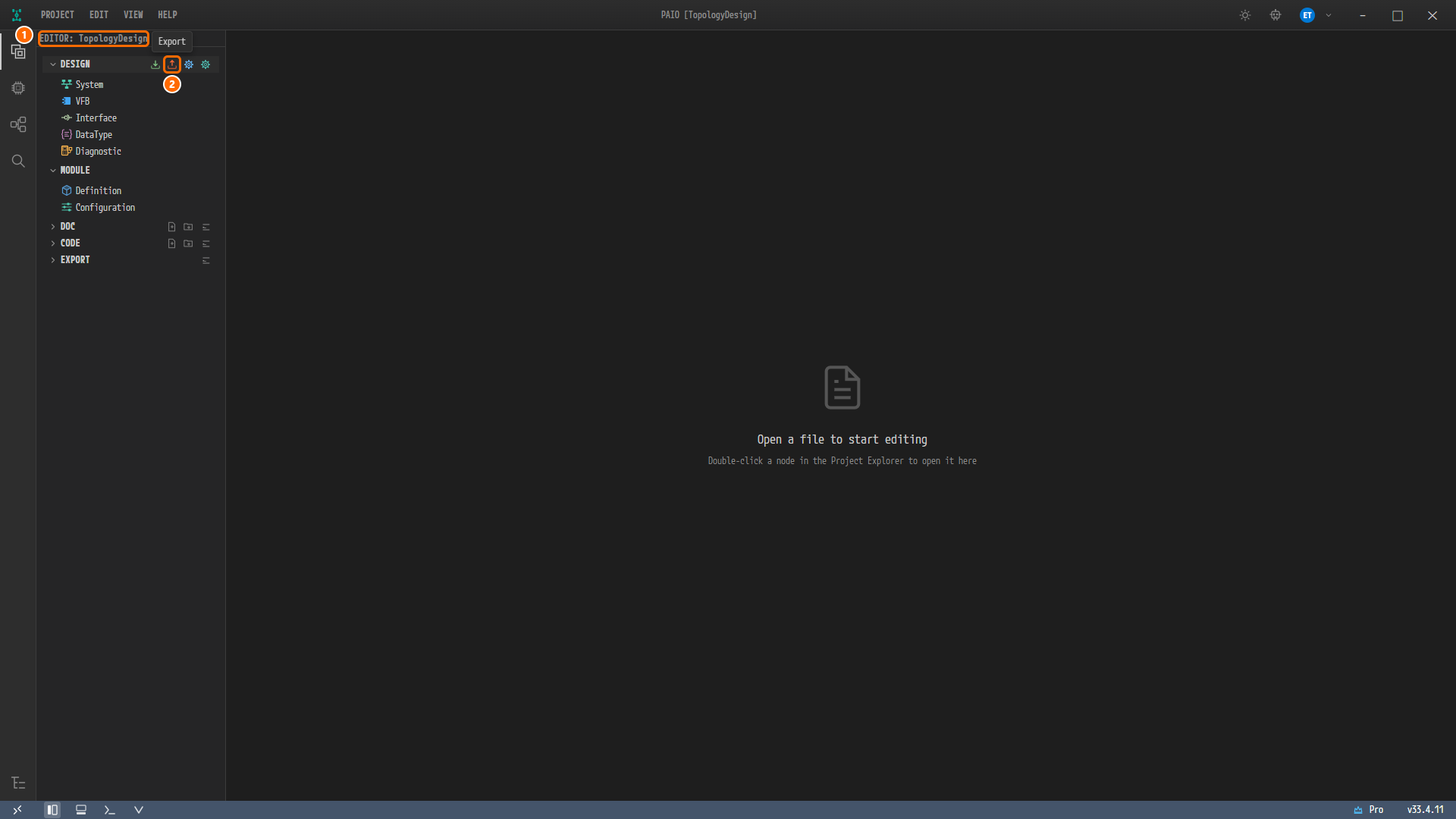
Figure 7-1. The Export icon of the DESIGN header. ① The view header
EDITOR: TopologyDesign, ② the Export icon under the mouse, with its tooltip Export. DESIGN and MODULE are open, and DOC, CODE and EXPORT are closed. No tab is open, so the editor area showsOpen a file to start editing. -
Click Export.
Note. Export is also in the menu that opens when you right-click the
designfolder in the Explorer (the Explorer icon at the bottom of the icon bar on the far left). Both run the same export.
Checking the Progress Dialog
-
No file picker or save-location dialog appears. The progress dialog Exporting to AUTOSAR appears right away. Shortly afterwards, when the export finishes, the message changes to
Export complete: 36 elements exported to TopologyDesign_*.arxml.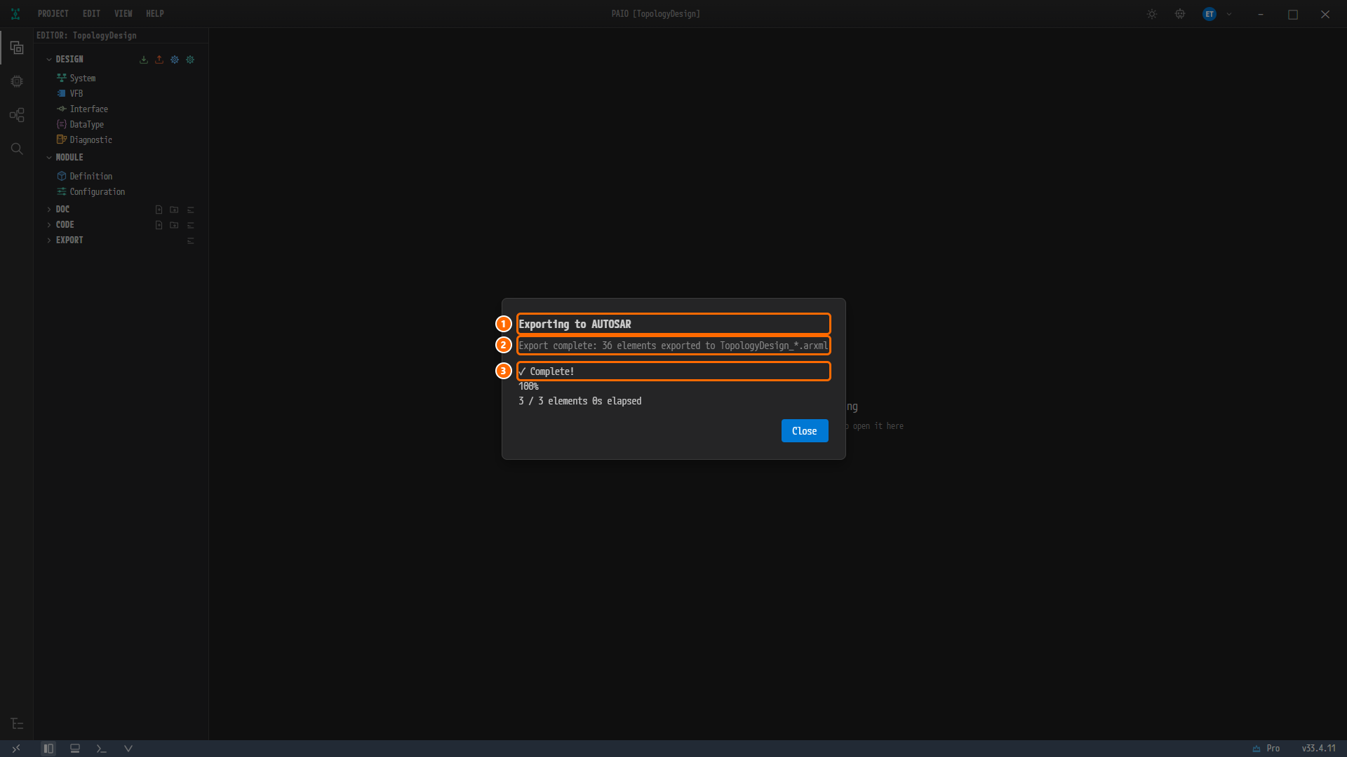
Figure 7-2. The progress dialog at the moment the export finished. ① The dialog title Exporting to AUTOSAR, ② the message
Export complete: 36 elements exported to TopologyDesign_*.arxml, ③ the step indicator✓ Complete!. Below them are100%,3 / 3 elementswith the elapsed time, and the Close button. -
The progress dialog closes by itself 2 seconds after completion. You can wait or click Close.
Note. The export always writes into the project's
exportfolder with the name<project name>_*.arxml. The design files in thedesignfolder do not change. The elapsed time in the progress dialog varies between0sand1sfrom run to run.
Viewing the Four Files in the export Folder
-
In the EDITOR view, click the EXPORT header to expand it. EXPORT lists the files of the project's
exportfolder: four files appear in name order, and no name is cut off.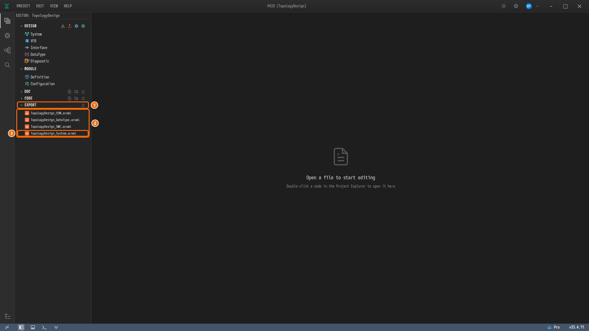
Figure 7-3. The expanded EXPORT section. ① The EXPORT header, ② the four files
TopologyDesign_COM.arxml,TopologyDesign_DataType.arxml,TopologyDesign_SWC.arxmlandTopologyDesign_System.arxml, ③TopologyDesign_System.arxml, which you open next.
The four files contain the following. All four files use the schema AUTOSAR_00054, and checking them with the schema bundled with PAIO gives zero errors and zero warnings. The sizes may differ slightly depending on the PAIO version.
| File | Contents | Size (bytes) |
|---|---|---|
TopologyDesign_COM.arxml | The ECU nodes ECU, ZONE and SLAVE_ECU and the HPC node HPC (with the controllers and connectors of each node), the clusters CanCluster, EthernetCluster and LinCluster, the network endpoints and the VLAN | 15 356 |
TopologyDesign_DataType.arxml | The basic data types PAIO puts into the export of every project. This design does not use data types | 30 921 |
TopologyDesign_SWC.arxml | One empty package SwComponentType | 379 |
TopologyDesign_System.arxml | The system System | 2 354 |
In the reference design all of this is in one file, System_Design.arxml.
Viewing the System System
Opening TopologyDesign_System.arxml in the XML Editor
-
In EXPORT, double-click
TopologyDesign_System.arxml. An XML editor tab opens, showing the file from line 1. The tab name isTopologyDesign:TopologyDesign_System.arxml, but the tab is narrow and shows only up toTopologyDesign:TopologyDesign_. You can tell which file is open from the row selected in EXPORT. -
Look at the status bar below the editor. It shows
Ln 1, Col 1,UTF-8,Schema: R25-11and✓ No problems. When the XML editor opens a file, it automatically checks the file against the AUTOSAR schema bundled with PAIO.✓ No problemsmeans there are no schema errors. The PROBLEMS header above it stays collapsed because there are no errors.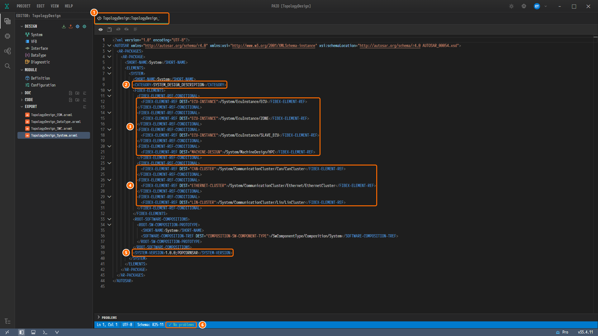
Figure 7-4.
TopologyDesign_System.arxmlright after opening (lines 1-45). ① The editor tab, ② line 9CATEGORYSYSTEM_DESIGN_DESCRIPTION, ③ lines 12-21, the four node references (ECU,ZONE,SLAVE_ECU,HPC), ④ lines 24-30, the references to the three clusters, ⑤ line 39SYSTEM-VERSION1.0.0;POPCORNSAR, ⑥✓ No problemsin the status bar. The file is selected in EXPORT.
Note. The file opens in view mode (read-only). The first toolbar button has the tooltip Switch to Edit mode and switches to edit mode. The other buttons are Save (Ctrl+S), Undo (Ctrl+Z), Redo (Ctrl+Y) and Format XML (Shift+Alt+F). This chapter does not change any file, so do not switch to edit mode.
Reading the Block
The lines of the SYSTEM System and where their values were entered are as follows.
| Line | Content | Where it was entered on screen |
|---|---|---|
| 7-8 | <SYSTEM>, <SHORT-NAME>System</SHORT-NAME> | Not entered. The system name the new project created |
| 9 | <CATEGORY>SYSTEM_DESIGN_DESCRIPTION</CATEGORY> | Not entered. A value fixed by the export |
| 12, 15, 18 | FIBEX-ELEMENT-REF DEST="ECU-INSTANCE" = /System/EcuInstance/ECU, /System/EcuInstance/ZONE, /System/EcuInstance/SLAVE_ECU | Not entered. The ECU nodes on the canvas of the System editor, in the order you added them in Project and Nodes |
| 21 | FIBEX-ELEMENT-REF DEST="MACHINE-DESIGN" = /System/MachineDesign/HPC | Not entered. The HPC node on the canvas, after the ECU nodes |
| 24, 27, 30 | CAN-CLUSTER /System/CommunicationCluster/Can/CanCluster, ETHERNET-CLUSTER /System/CommunicationCluster/Ethernet/EthernetCluster, LIN-CLUSTER /System/CommunicationCluster/Lin/LinCluster | The clusters created in CAN Bus, Ethernet Bus and LIN Bus |
| 33-38 | ROOT-SOFTWARE-COMPOSITIONS › ROOT-SW-COMPOSITION-PROTOTYPE System | Not entered. The root composition of the new project |
| 39 | <SYSTEM-VERSION>1.0.0;POPCORNSAR</SYSTEM-VERSION> | VERSION in the SYSTEM panel of the System editor in ECU Properties |
Note. The node list of the system information
design/SYSTEM.io.modelis empty, because the SYSTEM panel writes only the field you change (ECU Properties). The export therefore takes the node references from the nodes on the canvas: first the ECU nodes in the order you added them, then the HPC node.
Note. The
SOFTWARE-COMPOSITION-TREFon line 36 points at/SwComponentType/Composition/System, but this composition is in none of the four exported files.TopologyDesign_SWC.arxmlholds only one empty package. The schema check does not follow references to their targets, so✓ No problemsstays as it is. The reference design has no root composition.
Viewing the ECU Node ECU
Opening TopologyDesign_COM.arxml
-
In EXPORT, double-click
TopologyDesign_COM.arxml. A second tab opens, and it too shows only up toTopologyDesign:TopologyDesign_. The status bar shows✓ No problems. -
Scroll the mouse wheel down a little so that line 10
<ECU-INSTANCE>comes to the top of the editor.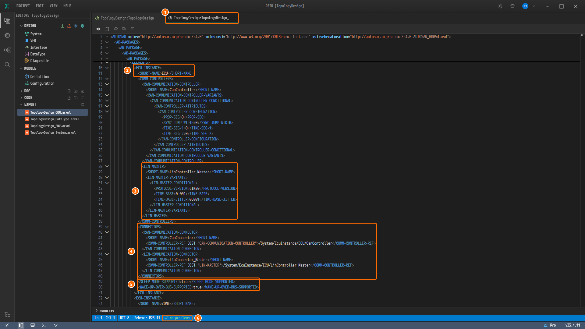
Figure 7-5. The ECU node
ECUinTopologyDesign_COM.arxml(lines 10-51). ① The active editor tab, ② lines 10-11,ECU-INSTANCEandSHORT-NAMEECU, ③ lines 28-37,LIN-MASTERLinController_Master(PROTOCOL-VERSIONLIN20,TIME-BASE0.001,TIME-BASE-JITTER0.001), ④ lines 39-48,CONNECTORS(CanConnector,LinConnector_Masterand the reference of each to its controller), ⑤ lines 49-50,SLEEP-MODE-SUPPORTEDtrueandWAKE-UP-OVER-BUS-SUPPORTEDtrue, ⑥✓ No problemsin the status bar. Lines 13-27 showCanControllerand its bit timing values.
Note. The top 5 lines of the editor (line numbers
2,3,4,6,7) are not the content at that place in the file. They are headers that pin the enclosing elements of the visible lines (AUTOSAR,AR-PACKAGES,AR-PACKAGE…) to the top of the editor.
Reading the Block
| Line | Content | Where it was entered on screen |
|---|---|---|
| 10-11 | <ECU-INSTANCE>, <SHORT-NAME>ECU</SHORT-NAME> | The node name in Project and Nodes |
| 13-27 | CAN-COMMUNICATION-CONTROLLER CanController: PROP-SEG, SYNC-JUMP-WIDTH, TIME-SEG-1, TIME-SEG-2 all 0 (lines 19-22) | PROPAGATION SEGMENT, SYNC JUMP WIDTH, TIME SEGMENT 1 and TIME SEGMENT 2 in CAN Bus |
| 28-37 | LIN-MASTER LinController_Master: PROTOCOL-VERSION LIN20 (line 32), TIME-BASE 0.001 (line 33), TIME-BASE-JITTER 0.001 (line 34) | PROTOCOL VERSION LIN 2.0, TIME BASE 1 ms and TIME BASE JITTER 1 ms in LIN Bus |
| 40-43 | CAN-COMMUNICATION-CONNECTOR CanConnector, COMM-CONTROLLER-REF = /System/EcuInstance/ECU/CanController (line 42) | The controller chosen as the connector's CONTROLLER in CAN Bus |
| 44-47 | LIN-COMMUNICATION-CONNECTOR LinConnector_Master, COMM-CONTROLLER-REF = /System/EcuInstance/ECU/LinController_Master (line 46) | The controller chosen as the connector's CONTROLLER in LIN Bus |
| 49-50 | SLEEP-MODE-SUPPORTED true, WAKE-UP-OVER-BUS-SUPPORTED true | SLEEP MODE SUPPORTED and WAKE-UP OVER BUS in ECU Properties |
The two partitions ECU_Partition0 and ECU_Partition1 of ECU in the reference design are not in this block. As you saw in ECU Properties, the System editor has no field for entering partitions.
The other two ECU nodes have the same shape. Look at the following lines in the same file.
| Node | Where to look | Content |
|---|---|---|
ZONE | lines 52-82 | CanCommController (name only, line 56), EthernetCommController (MAC-UNICAST-ADDRESS 11:22:ee:44:55:66, line 62), CanConnector, EthernetConnector (NETWORK-ENDPOINT-REF → ZONE_EthernetConnector_Endpoint, line 76), lines 80-81 SLEEP-MODE-SUPPORTED and WAKE-UP-OVER-BUS-SUPPORTED true |
SLAVE_ECU | lines 83-103 | LIN-SLAVE LinSlaveController (PROTOCOL-VERSION LIN20, line 90), LinConnector (→ LinSlaveController, line 98), lines 101-102 SLEEP-MODE-SUPPORTED and WAKE-UP-OVER-BUS-SUPPORTED true |
Viewing the HPC Node HPC
Jumping to MACHINE-DESIGN with Find
-
Click inside the editor and press
Ctrl+F. The find widget opens at the top right of the editor. -
Type
<MACHINE-DESIGN>. The find widget shows1 of 1, and the editor jumps to line 109 and selects the text. The status bar showsLn 109, Col 29and16 selected. -
Find places the found line in the middle of the editor. To see the whole block, scroll the mouse wheel down a few notches so that line 109 comes to the top of the editor.
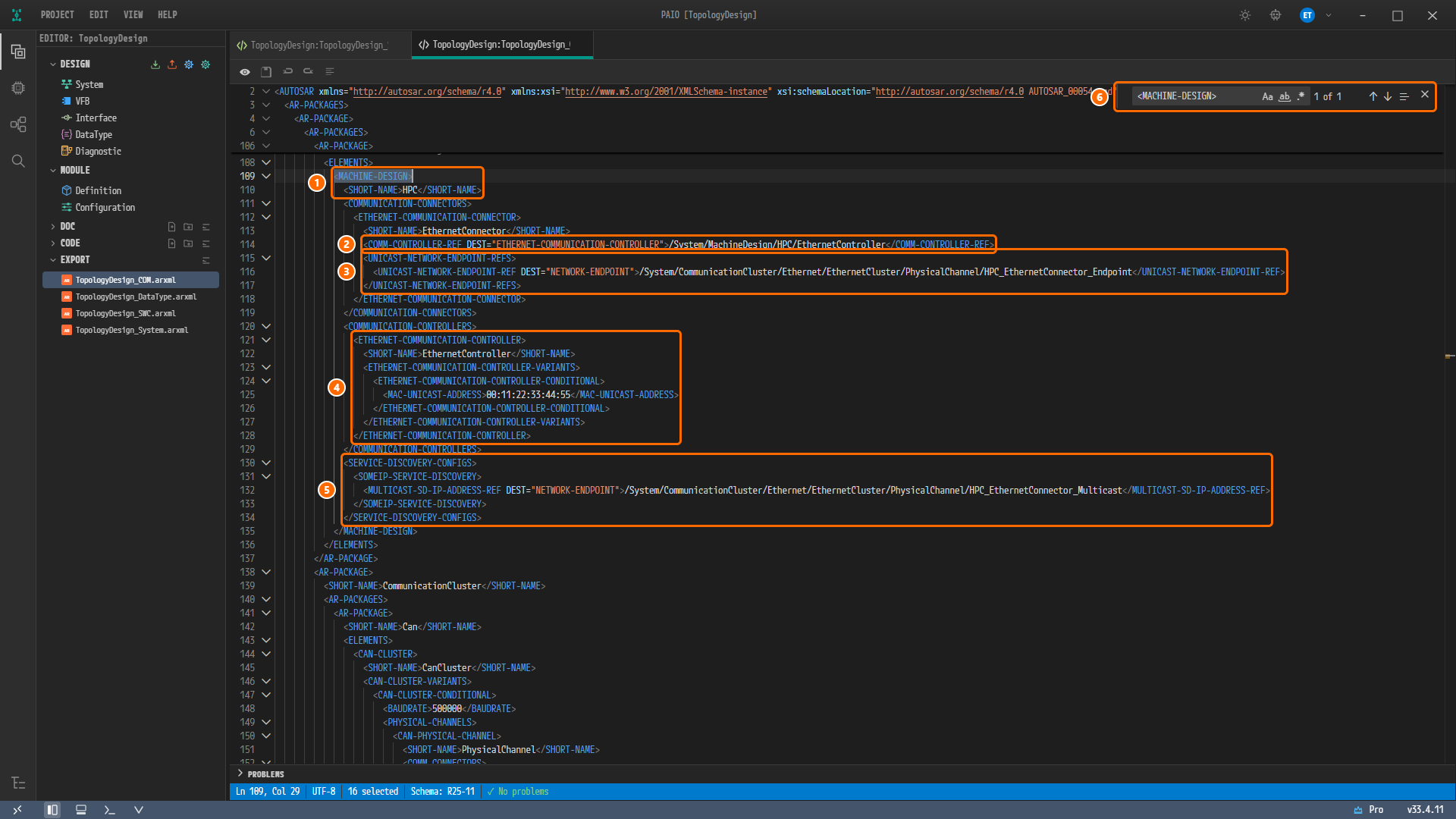
Figure 7-6. The HPC node reached with find (lines 109-135). ① Lines 109-110,
MACHINE-DESIGNandSHORT-NAMEHPC, ② line 114COMM-CONTROLLER-REF(/System/MachineDesign/HPC/EthernetController), ③ lines 115-117UNICAST-NETWORK-ENDPOINT-REF(HPC_EthernetConnector_Endpoint), ④ lines 121-128ETHERNET-COMMUNICATION-CONTROLLEREthernetController(MAC-UNICAST-ADDRESS00:11:22:33:44:55), ⑤ lines 130-134SERVICE-DISCOVERY-CONFIGS, ⑥ the find widget (<MACHINE-DESIGN>,1 of 1). Further down,CanClusterand line 148BAUDRATE500000are visible.
Reading the Block
| Line | Content | Where it was entered on screen |
|---|---|---|
| 109-110 | <MACHINE-DESIGN>, <SHORT-NAME>HPC</SHORT-NAME> | The HPC node in Project and Nodes. An HPC node goes out as a MACHINE-DESIGN, not as an ECU-INSTANCE |
| 112-113 | ETHERNET-COMMUNICATION-CONNECTOR EthernetConnector | The connector created in Ethernet Bus |
| 114 | COMM-CONTROLLER-REF = /System/MachineDesign/HPC/EthernetController | The connector's CONTROLLER EthernetController |
| 115-117 | UNICAST-NETWORK-ENDPOINT-REF = /System/CommunicationCluster/Ethernet/EthernetCluster/PhysicalChannel/HPC_EthernetConnector_Endpoint | The connector's UNICAST IPV4 ADDRESS 192.168.0.11 |
| 121-128 | ETHERNET-COMMUNICATION-CONTROLLER EthernetController, MAC-UNICAST-ADDRESS 00:11:22:33:44:55 (line 125) | The controller's MAC ADDRESS |
| 130-134 | SERVICE-DISCOVERY-CONFIGS › SOMEIP-SERVICE-DISCOVERY › MULTICAST-SD-IP-ADDRESS-REF = …/PhysicalChannel/HPC_EthernetConnector_Multicast (line 132) | Not entered. The export creates it when the connector has a MULTICAST IPV4 ADDRESS |
Note. Inside the
MACHINE-DESIGN, the connector (lines 111-119) comes before the controller (lines 120-129). The reference design has the same order.
Line 114 and lines 115-117 are where this tutorial corrects the reference design. The section "Where the HPC Connector Is Corrected" later in this chapter explains them.
Viewing the Ethernet Endpoints
Changing the Search String
-
Clear the input box of the find widget and type
<NETWORK-ENDPOINTS>. The find widget shows1 of 1, and the editor jumps to line 185. The status bar showsLn 185, Col 46and19 selected. -
As before, scroll the mouse wheel down so that line 185 comes to the top of the editor.
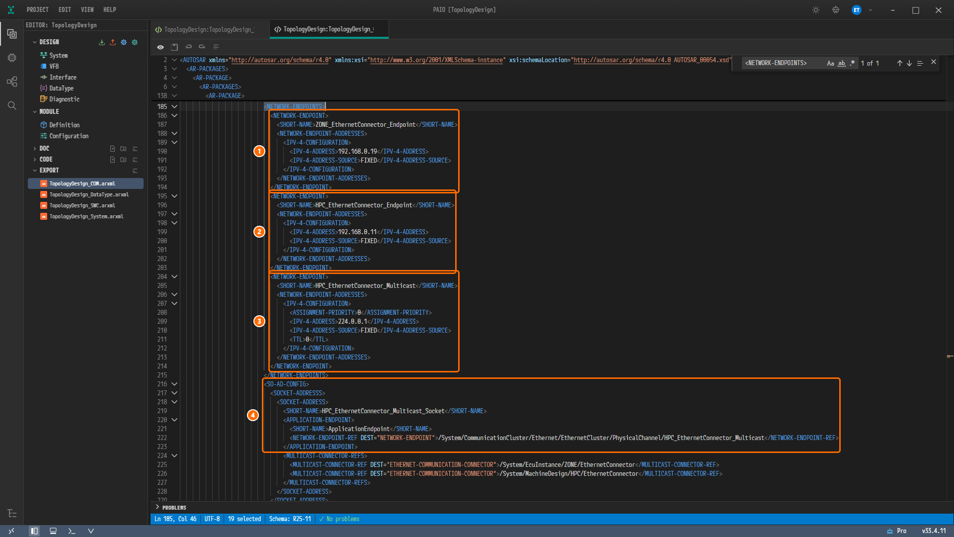
Figure 7-7. The endpoints of the Ethernet channel reached with find (lines 185-228). ① Lines 186-194
ZONE_EthernetConnector_Endpoint(192.168.0.19,FIXED), ② lines 195-203HPC_EthernetConnector_Endpoint(192.168.0.11,FIXED), ③ lines 204-214HPC_EthernetConnector_Multicast(224.0.0.1,FIXED,ASSIGNMENT-PRIORITY0,TTL0), ④ lines 216-223, the socketHPC_EthernetConnector_Multicast_SocketandApplicationEndpointofSO-AD-CONFIG. Below them,MULTICAST-CONNECTOR-REFSon lines 224-227 point at theEthernetConnectorofZONEand ofHPC.
Reading the Block
| Line | Endpoint | Address | Where it was entered on screen |
|---|---|---|---|
| 186-194 | ZONE_EthernetConnector_Endpoint | IPV-4-ADDRESS 192.168.0.19 (line 190), IPV-4-ADDRESS-SOURCE FIXED (line 191) | UNICAST IPV4 ADDRESS and FIXED of ADDRESS SOURCE of the ZONE connector |
| 195-203 | HPC_EthernetConnector_Endpoint | 192.168.0.11 (line 199), FIXED (line 200) | UNICAST IPV4 ADDRESS and FIXED of the HPC connector |
| 204-214 | HPC_EthernetConnector_Multicast | 224.0.0.1 (line 209), FIXED (line 210), ASSIGNMENT-PRIORITY 0 (line 208), TTL 0 (line 211) | MULTICAST IPV4 ADDRESS of the HPC connector. ASSIGNMENT-PRIORITY and TTL are values the export adds |
You do not enter endpoint names on screen. The export names them <node>_<connector>_Endpoint and <node>_<connector>_Multicast. The SO-AD-CONFIG on lines 216-230 also appears without any input. For every connector with a multicast address, the export creates a socket <node>_<connector>_Multicast_Socket and its APPLICATION-ENDPOINT, and points it at the multicast endpoint (line 222).
Viewing the VLAN and the LIN Cluster
Changing the Search String
-
Clear the input box of the find widget and type
<VLAN>. The find widget shows1 of 1, and the editor jumps to line 231. The status bar showsLn 231, Col 33and6 selected. -
Scroll the mouse wheel down so that line 231 comes to the top of the editor.
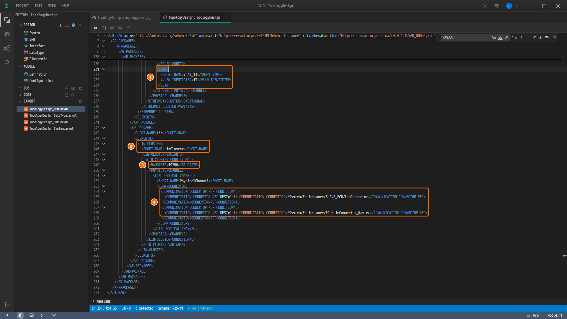
Figure 7-8. The VLAN and the LIN cluster reached with find (lines 230-273). ① Lines 231-234,
VLANVLAN_13andVLAN-IDENTIFIER13, ② lines 245-246,LIN-CLUSTERandSHORT-NAMELinCluster, ③ line 249BAUDRATE19200, ④ lines 254-258, the references to theLinConnectorofSLAVE_ECU(line 255) and theLinConnector_MasterofECU(line 258) attached to the channel. The channel ends at line 261 with noBUS-IDLE-TIMEOUT-PERIOD. -
Press the
Escapekey to close the find widget.
Reading the Block
| Line | Content | Where it was entered on screen |
|---|---|---|
| 231-234 | VLAN VLAN_13, VLAN-IDENTIFIER 13 | The VLAN ID 13 entered on the channel in Ethernet Bus. The export gives it the name VLAN_13 as VLAN_<ID> |
| 245-246 | LIN-CLUSTER LinCluster | The cluster's NAME in LIN Bus |
| 249 | BAUDRATE 19200 | Not entered. A value PAIO saves into a new LIN cluster |
| 252 | Channel PhysicalChannel | The cluster's CHANNEL NAME |
| 255, 258 | COMMUNICATION-CONNECTOR-REF = /System/EcuInstance/SLAVE_ECU/LinConnector, /System/EcuInstance/ECU/LinConnector_Master | The two connectors attached to the cluster. The order is the same too |
| 251-261 | LIN-PHYSICAL-CHANNEL with no BUS-IDLE-TIMEOUT-PERIOD | Not entered. IDLE TIMEOUT of the cluster refused 10 ms in LIN Bus and stayed empty |
The other two clusters have the same shape.
| Cluster | Where to look | Content |
|---|---|---|
CanCluster | lines 144-164 | BAUDRATE 500000 (line 148), the CanConnector of ZONE and of ECU on the channel PhysicalChannel (lines 154, 157) |
EthernetCluster | lines 170-239 | The EthernetConnector of ZONE and of HPC on the channel PhysicalChannel (lines 179, 182), the three endpoints (lines 185-215), SO-AD-CONFIG (lines 216-230), VLAN_13 (lines 231-234) |
Where the HPC Connector Is Corrected
The HPC Ethernet connector of the reference design has two defects. This tutorial built this connector in corrected form in Ethernet Bus. Putting the same connector of the two files side by side gives the following.
| Item | Reference design (System_Design.arxml lines 201-208) | Your export (TopologyDesign_COM.arxml lines 112-118) |
|---|---|---|
| Location | /System/VehicleTopology/Ecu/HPC/EthernetConnector | /System/MachineDesign/HPC/EthernetConnector |
COMM-CONTROLLER-REF | None | /System/MachineDesign/HPC/EthernetController (line 114) |
| Unicast endpoint | …/PhysicalChannel/ZONE_Endpoint (line 206) = 192.168.0.19. This is the address of the ZONE connector | …/PhysicalChannel/HPC_EthernetConnector_Endpoint (line 116) = 192.168.0.11 |
CATEGORY, CREATE-ECU-WAKEUP-SOURCE | WIRED, false | None, none |
- It connects the controller. The node
HPChas the Ethernet controllerEthernetController, yet the connector of the reference design does not point at it. The connector of the same name onZONEpoints at its own controllerEthernetCommController(reference design line 273). A connector attaches to the bus through its controller, so this tutorial connects the two. - It uses the address of
HPCitself. Following the reference design, the two connectors ofZONEandHPCwould have the same address192.168.0.19, and the endpointHPC_Endpoint(192.168.0.11), which is the address ofHPC, would be left unused by any connector. This tutorial enters192.168.0.11on theHPCconnector. - Validation does not report this defect. The controller reference of a connector is optional in the AUTOSAR schema, and the error
constr_5398for a connector without a controller checks only the connectors of ECU nodes. That is why, even if you import the reference design into PAIO as is and validate it, the VALIDATION panel showsNo validation issues..
How Your Export Differs from the Reference Design
When you put the reference design file System_Design.arxml side by side with the four files of your export, the line counts and contents differ. This section collects every difference and gives a one-line reason for each. The comparison paired the elements that have a name (SHORT-NAME) by their package path.
Summary
| Reference design | Your export | |
|---|---|---|
| Files | 1 | 4 |
| Elements with a name (packages excluded) | 29 | 79 |
| Elements with the same path | 1 | 1 |
| Elements moved to another package | 22 | 22 |
| Elements renamed in the same place | 4 | 4 |
| Elements only in the reference design | 2 | — |
| Elements only in your export | — | 52 |
- Of the 27 elements that have a counterpart, 14 differ in values or references and 13 have the same values and references.
- The design content is all there except the two partitions and a few values in the tables below: the four nodes with their controllers and connectors, the sleep and bus wake-up settings, the three clusters and their channels, the addresses of the three endpoints, the VLAN ID and the system version.
- The remaining differences have five kinds of reason.
| Reason | Meaning |
|---|---|
| Naming rule | Packages, names, notation and order fixed by the PAIO export |
| Generated automatically | Elements and values PAIO adds on its own to a project built on screen |
| No field on screen | Values that cannot be entered in the System editor or its SYSTEM panel: there is no field, or the field refuses the value |
| Tutorial intent | Values this tutorial changes on purpose |
| Defect in the reference design | Places where the reference design file itself is wrong |
Caution. The controller reference and the unicast endpoint of the
HPCconnector are deliberate departures from the reference design. See the section "Where the HPC Connector Is Corrected" above.
System
| Element | Result | Reason |
|---|---|---|
SYSTEM System | Value differs: CATEGORY SYSTEM_DESCRIPTION → SYSTEM_DESIGN_DESCRIPTION (System file line 9) | Naming rule, no field on screen: the export always writes the system category as SYSTEM_DESIGN_DESCRIPTION. The SYSTEM panel has no field for this value |
FIBEX-ELEMENTS of SYSTEM System | Order differs: the same seven references in another order (System file lines 12-30). The reference design lists CanCluster, ECU, EthernetCluster, HPC, LinCluster, SLAVE_ECU, ZONE, your export ECU, ZONE, SLAVE_ECU, HPC, CanCluster, EthernetCluster, LinCluster | Naming rule: the export writes the ECU nodes in the order you added them, then the HPC node, then the clusters. There is no field for the order |
SYSTEM-VERSION | Same | You entered VERSION in the SYSTEM panel of the System editor in ECU Properties |
Nodes
| Element | Result | Reason |
|---|---|---|
ECU-INSTANCE ECU, ZONE, SLAVE_ECU, MACHINE-DESIGN HPC with their 6 controllers and 6 connectors | Moved: /System/VehicleTopology/Ecu/<node> → /System/EcuInstance/<node> (HPC to /System/MachineDesign/HPC) | Naming rule: the export places ECU nodes in /System/EcuInstance and HPC nodes in /System/MachineDesign. There is no field for choosing the package. The element names and substructure are the same |
ECU-PARTITION ECU_Partition0 (EXEC-IN-USER-MODE true), ECU_Partition1 (false) | Only in the reference design | No field on screen: the System editor has no field for partitions, and the export does not write partitions either |
LIN-MASTER LinController_Master | Value differs: WAKE-UP-BY-CONTROLLER-SUPPORTED true is missing | Tutorial intent: WAKE-UP BY CONTROLLER of the LIN MASTER panel is not clicked in LIN Bus, and an item without a value is left out of the export |
CAN-COMMUNICATION-CONTROLLER CanCommController (ZONE) | Value differs: the empty CAN-COMMUNICATION-CONTROLLER-CONDITIONAL is missing (COM file lines 55-57) | Naming rule: for a CAN controller with no attributes at all, the export does not write the empty child element. The design content is the same |
ETHERNET-COMMUNICATION-CONTROLLER EthernetCommController (ZONE) | Values differ: CATEGORY WIRED and MAC-LAYER-TYPE X-MII are missing, MAC-UNICAST-ADDRESS 11:22:EE:44:55:66 → 11:22:ee:44:55:66 (COM file line 62) | No field on screen: there is no CATEGORY field. Tutorial intent: MAC LAYER TYPE is not clicked, because clicking it exports XMII, a value not in the schema (the "Caution" in Ethernet Bus). Naming rule: the MAC address is stored in lowercase and is the same address |
ETHERNET-COMMUNICATION-CONNECTOR EthernetConnector (ZONE) | Value differs: CATEGORY WIRED is missing | No field on screen |
MACHINE-DESIGN HPC | Value differs: SERVICE-DISCOVERY-CONFIGS is added (COM file lines 130-134) | Generated automatically: when the HPC connector has a MULTICAST IPV4 ADDRESS, the export creates a configuration that points at that multicast endpoint as the SD address. In the reference design, no element points at SOMEIP_SD_Multicast |
ETHERNET-COMMUNICATION-CONTROLLER EthernetController (HPC) | Values differ: CATEGORY WIRED, WAKE-UP-BY-CONTROLLER-SUPPORTED false and MAC-LAYER-TYPE X-MII are missing | No field on screen: there are no fields for CATEGORY and controller wake-up. Tutorial intent: MAC LAYER TYPE is not clicked |
ETHERNET-COMMUNICATION-CONNECTOR EthernetConnector (HPC) | Values differ: COMM-CONTROLLER-REF is added (COM file line 114), the unicast endpoint ZONE_Endpoint → HPC_EthernetConnector_Endpoint (line 116), CATEGORY WIRED and CREATE-ECU-WAKEUP-SOURCE false are missing | Defect in the reference design, tutorial intent: the section "Where the HPC Connector Is Corrected" above. CATEGORY has no field on screen. CREATE-ECU-WAKEUP-SOURCE has no value because you do not touch PARTIAL NETWORK › CREATE ECU WAKEUP SOURCE of the connector, and items without a value are left out of the export |
The three ECU-INSTANCE elements, CanController, LinSlaveController, the 2 CAN connectors, the 2 LIN connectors | Same (only the location moved) | The sleep and bus wake-up settings, the bit timing, the LIN protocol version LIN20 and the controller references are all the same |
Clusters and Channels
| Element | Result | Reason |
|---|---|---|
| The three clusters and the three channels | Moved: /System/VehicleTopology/Cluster/… → /System/CommunicationCluster/Can/…, /System/CommunicationCluster/Ethernet/…, /System/CommunicationCluster/Lin/… | Naming rule: the export places clusters in a package per bus type. There is no field for choosing the package |
CAN-CLUSTER CanCluster | Values differ: PROTOCOL-NAME CAN-FD is missing, BAUDRATE 500000 is added (COM file line 148) | Tutorial intent: PROTOCOL NAME in the PROTOCOL section of the CAN CLUSTER panel is left empty in CAN Bus. Generated automatically: 500000 is a value PAIO saves into a new CAN cluster |
ETHERNET-CLUSTER EthernetCluster | Value differs: PROTOCOL-NAME IEEE 802.3 is missing | No field on screen: the ETHERNET CLUSTER panel has no PROTOCOL section |
ETHERNET-PHYSICAL-CHANNEL PhysicalChannel | Value differs: CATEGORY WIRED is missing | No field on screen |
LIN-CLUSTER LinCluster | Value differs: BAUDRATE 19200 is added (COM file line 249) | Generated automatically: a value PAIO saves into a new LIN cluster |
LIN-PHYSICAL-CHANNEL PhysicalChannel | Value differs: BUS-IDLE-TIMEOUT-PERIOD 0.01 is missing | No field on screen: IDLE TIMEOUT of the LIN CLUSTER panel accepts only 0.1 seconds or more (LIN Bus). The attached connectors and their order are the same |
NETWORK-ENDPOINT HPC_Endpoint, ZONE_Endpoint | Renamed: HPC_EthernetConnector_Endpoint, ZONE_EthernetConnector_Endpoint | Naming rule, no field on screen: an endpoint is entered as the connector's UNICAST IPV4 ADDRESS, and the export names it <node>_<connector>_Endpoint. The address and FIXED are the same |
NETWORK-ENDPOINT SOMEIP_SD_Multicast | Renamed: HPC_EthernetConnector_Multicast. Values differ: ASSIGNMENT-PRIORITY 0 and TTL 0 are added | Naming rule: it is entered as MULTICAST IPV4 ADDRESS of the HPC connector, and its name is <node>_<connector>_Multicast. The two values are the 0 the export puts into a multicast endpoint |
VLAN Vlan_13 | Renamed: VLAN_13 | Naming rule, no field on screen: the channel has only the VLAN ID field, and the export names the VLAN VLAN_<ID>. VLAN-IDENTIFIER 13 is the same |
CAN-PHYSICAL-CHANNEL PhysicalChannel | Same (only the location moved) | The attached connectors and their order are the same |
Elements Only in Your Export
| Group | Count | Elements | Reason |
|---|---|---|---|
| SD socket | 2 | SOCKET-ADDRESS HPC_EthernetConnector_Multicast_Socket, APPLICATION-ENDPOINT ApplicationEndpoint | Generated automatically: the export creates them for every connector with a multicast address |
| Basic data types | 49 | SW-BASE-TYPE boolean, float32, float64, sint8 … (12), IMPLEMENTATION-DATA-TYPE (13), STD-CPP-IMPLEMENTATION-DATA-TYPE (11), APPLICATION-PRIMITIVE-DATA-TYPE (11) and DATA-TYPE-MAPPING-SET (2) in TopologyDesign_DataType.arxml | Generated automatically: the basic types PAIO puts into every export. This design does not use them |
| Root composition | 1 | ROOT-SW-COMPOSITION-PROTOTYPE System | Generated automatically: the root composition that the system of a new project has |
Note. Your export has no NM or TP elements. This design leaves network management (NM) off on
CanClusterandEthernetClusterand the transport protocol (TP) off onCanClusterandLinCluster(CAN Bus, Ethernet Bus, LIN Bus). The reference design has neither.
Differences That Are Not Design Information
| Item | Reference design | Your export |
|---|---|---|
UUID attribute | On all 33 elements with a name | None |
| File layout | One file | Four files: _COM, _DataType, _SWC, _System |
| Element order | The order of the reference design | The order of the export rules |
| Namespace and schema | http://autosar.org/schema/r4.0, AUTOSAR_00054.xsd | Same |
Values You Do Not Create on Screen at a Glance
Collecting only the reference design values from the tables above that you do not create on screen gives the following.
| Reference design value | Location | Your export | Chapter that covers it |
|---|---|---|---|
ECU_Partition0 (EXEC-IN-USER-MODE true), ECU_Partition1 (false) | ECU | None | ECU Properties |
PROTOCOL-NAME CAN-FD | CanCluster | None | CAN Bus |
PROTOCOL-NAME IEEE 802.3 | EthernetCluster | None | Ethernet Bus |
CATEGORY WIRED | The Ethernet channel, 2 controllers, 2 connectors | None | Ethernet Bus |
MAC-LAYER-TYPE X-MII | The 2 Ethernet controllers | None | Ethernet Bus |
WAKE-UP-BY-CONTROLLER-SUPPORTED | LinController_Master (true), EthernetController of HPC (false) | None | LIN Bus, Ethernet Bus |
BUS-IDLE-TIMEOUT-PERIOD 0.01 | The channel PhysicalChannel of LinCluster | None | LIN Bus |
CATEGORY SYSTEM_DESCRIPTION | SYSTEM System | SYSTEM_DESIGN_DESCRIPTION | This chapter |
The names HPC_Endpoint, ZONE_Endpoint, SOMEIP_SD_Multicast, Vlan_13 | The Ethernet channel | HPC_EthernetConnector_Endpoint, ZONE_EthernetConnector_Endpoint, HPC_EthernetConnector_Multicast, VLAN_13 | Ethernet Bus |
CREATE-ECU-WAKEUP-SOURCE false | EthernetConnector of HPC | None | This chapter |
The packages /System/VehicleTopology/Ecu, /System/VehicleTopology/Cluster | All nodes and clusters | /System/EcuInstance, /System/MachineDesign, /System/CommunicationCluster/… | This chapter |
Why Is It Designed This Way?
- You check the result in the XML editor. Opening a file runs the schema check along with it, so
✓ No problemstells you right away that the structure is correct. However, this check does not verify that the targets of references actually exist. - The differences are mostly locations and names. Of the 29 elements of the reference design, 27 have a counterpart in your export, and most of the differences come from the package and naming rules of the export. Only the two partitions are missing as whole elements.
- The
HPCconnector does not follow the reference design. The shape in the reference design, with no controller and pointing at the address ofZONE, is a defect, so this tutorial builds it with the own controller ofHPCand the address192.168.0.11.
Checklist
- EXPORT in the EDITOR view lists the four files
TopologyDesign_COM.arxml,TopologyDesign_DataType.arxml,TopologyDesign_SWC.arxmlandTopologyDesign_System.arxml. - The export progress dialog Exporting to AUTOSAR showed
Export complete: 36 elements exported to TopologyDesign_*.arxmland✓ Complete!, and then closed. - The status bar of the two tabs with
TopologyDesign_System.arxmlandTopologyDesign_COM.arxmlshowsSchema: R25-11and✓ No problems. - Line 39 of
TopologyDesign_System.arxmlisSYSTEM-VERSION1.0.0;POPCORNSAR, and lines 12-21 hold the references to the nodesECU,ZONE,SLAVE_ECUandHPC. - Searching
TopologyDesign_COM.arxmlfor<MACHINE-DESIGN>gives1 of 1, line 114 points at/System/MachineDesign/HPC/EthernetController, and line 116 points atHPC_EthernetConnector_Endpoint. - Searching for
<NETWORK-ENDPOINTS>gives1 of 1, and the addresses of the three endpoints are192.168.0.19,192.168.0.11and224.0.0.1. - Searching for
<VLAN>gives1 of 1, theVLAN-IDENTIFIERofVLAN_13is13, and the channel ofLinClusterrefers to theLinConnectorofSLAVE_ECUand theLinConnector_MasterofECU. - Neither tab carries the modified mark
●.
Next Step
The main part of the tutorial ends here. Continue with the Appendix.