VFB and Virtual Function Clusters
What You Will Do
In this chapter you build a composition and an atomic SWC by hand in the VFB editor, then layer a VFC (Virtual Function Cluster) on top of them. In AUTOSAR a VFC is not a separate element — it is expressed as a PortGroup. You collect the SWC ports that participate in a function into a single PortGroup and keep that PortGroup name identical from the atomic SWC up to the root composition.
First you create the composition ParkSensor_RR and the atomic SWC ParkDistanceSensing inside it from scratch. Next you review the structure of the VFB root, and then you create the PortGroup VFC_ParkAssist on the ParkDistanceSensing you just built. Finally you use the VFC (PNC Overlay) icon to see which compositions participate in each VFC.
When you finish this chapter, your project is in the following state.
- The root
PncVehiclecontains the compositionParkSensor_RR, which contains the atomic SWCParkDistanceSensing. The twoParkDistanceports are joined by a delegation connector, and the composition'sParkDistanceport is joined to theParkDistanceport ofSouthZoneby an assembly connector at the root. - The
ParkSensor_RRcomposition is mapped to the nodeParkSensor_RR [ECU]in the System editor. ParkDistanceSensinghas the PortGroupVFC_ParkAssist(CATEGORYPARTIAL_NETWORKING, OUTER PORTSParkDistance).- The parent composition
ParkSensor_RRand the rootPncVehicleautomatically receive a PortGroup of the same name,VFC_ParkAssist. - You understand the VFC family rule (the same-name rule) and can check which compositions participate in a VFC with the PNC Overlay.
Before You Begin
- Finish Interfaces and SOME/IP Services first. The ports in this chapter use the PortInterface
SRI_ParkDistancecreated in Chapter 5. - Up to the previous chapter the VFB root
PncVehicleis empty. In this chapter you create one composition per node in the System editor, 14 in total. You follow the full procedure for the representative compositionParkSensor_RR, and you build the remaining 13 the same way using the table in The Remaining 13 Compositions. - At the end of the representative procedure you connect the port of
ParkSensor_RRto a port ofSouthZone. So if you create the 13 compositions in the table first and then follow the representative procedure, your screen matches the figures. The procedure figures in this chapter were also captured with the 13 compositions already in place. - The
SouthZonecomposition has an R-PortParkDistance(PortInterfaceSRI_ParkDistance). It is the counterpart of the assembly connector you create in this chapter. - The node
ParkSensor_RR [ECU]in the System editor, created in Topology Design, exists. It is the target of ECU/HPC Mapping in this chapter. - There is not a single PortGroup yet, and there is no link between PNCs and VFCs yet either (the VFC reference of a PNC mapping).
Creating the SWC and the Composition
As the representative case, you create the composition ParkSensor_RR for an end ECU and the atomic SWC ParkDistanceSensing inside it.
Creating the Composition
-
In the EDITOR view on the left, click VFB under DESIGN.
The PNC:VFB tab opens, and the root composition name
PncVehicleappears at the top left of the canvas. -
Click Auto Layout on the toolbar at the bottom of the canvas. It is the fourth button, after Zoom In, Zoom Out, and Fit to View.
A progress dialog appears briefly and disappears, and the compositions are arranged. If the whole layout does not fit on screen, click Fit to View. The arrangement produced by Auto Layout counts as an unsaved change and is saved together with the VFB editor later.
-
Right-click the empty canvas near
SouthZoneand click Add Composition.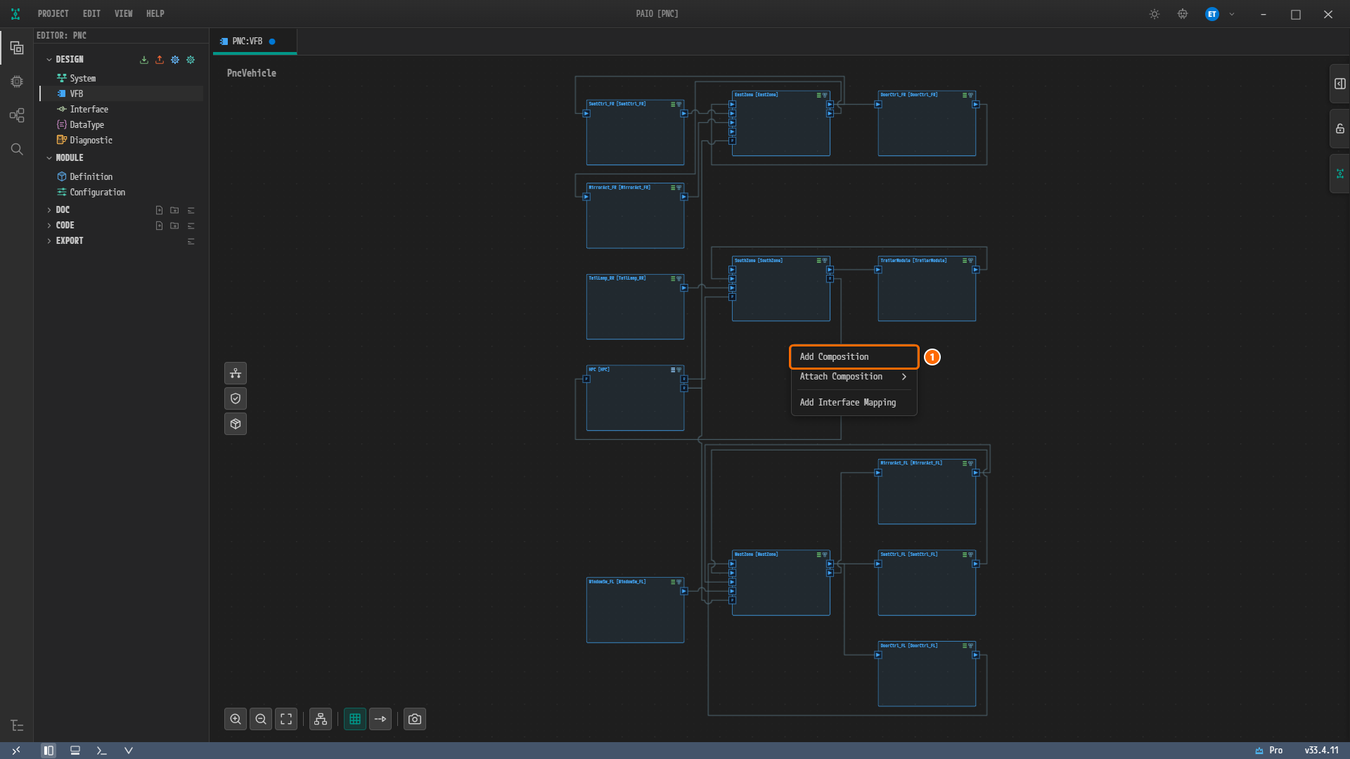
Figure 6-1. Right-clicking the empty canvas in a VFB root that holds 13 compositions. ① Add Composition, the item to click. The remaining menu items are Attach Composition and Add Interface Mapping.
Note. Later you have to connect a port of this composition to a port of
SouthZone. It is easier if you right-click a spot where both nodes are visible at the same time.A node appears where you right-clicked. Its default name is
Composition_0. -
Click the new node. The COMPOSITION properties panel appears on the right.
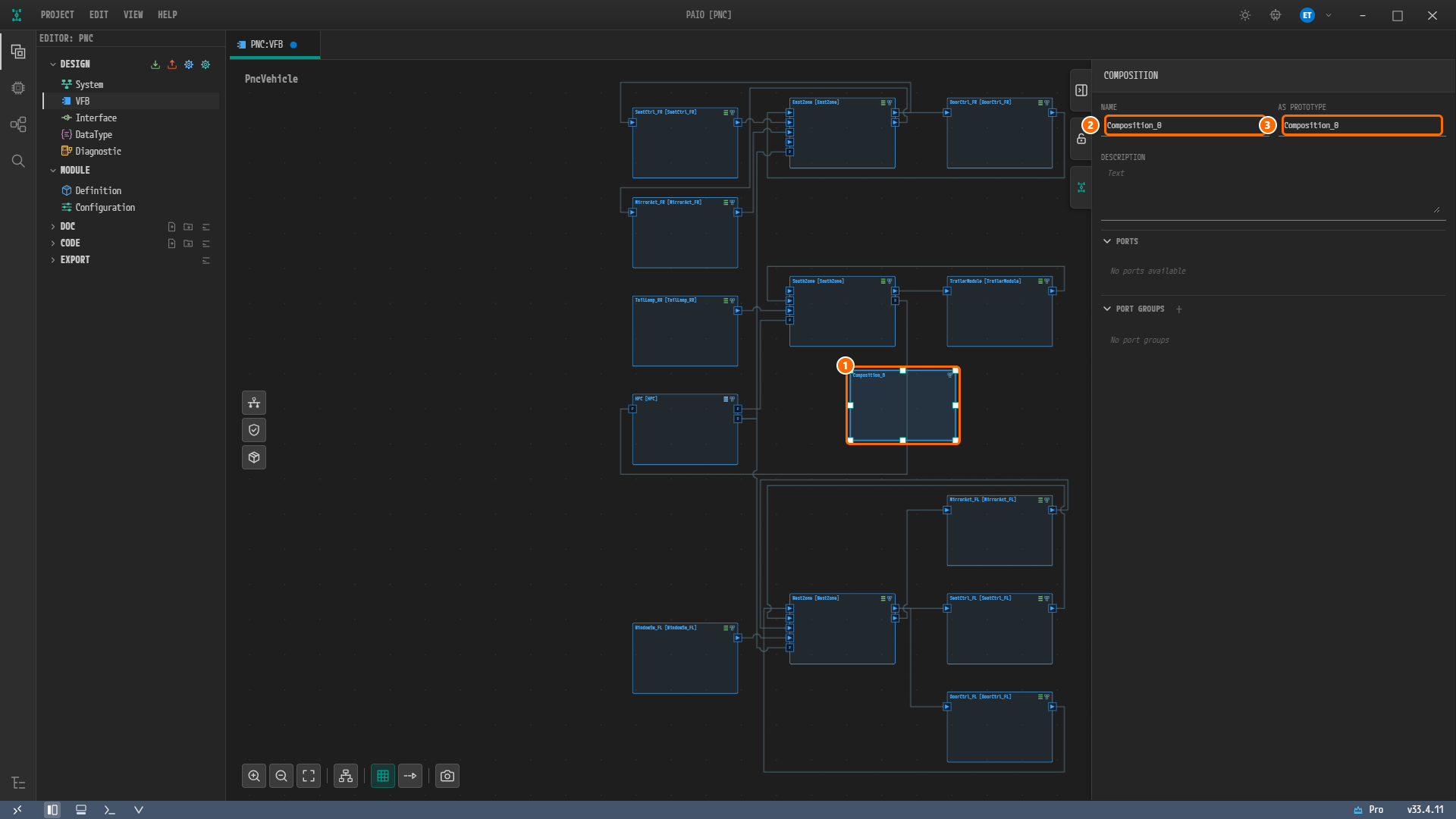
Figure 6-2. The new composition. ① The node
Composition_0on the canvas. ② NAME =Composition_0. ③ AS PROTOTYPE =Composition_0. Below them you see PORTS =No ports availableand PORT GROUPS =No port groups. -
Type
ParkSensor_RRin NAME and press Tab. Then typeParkSensor_RRin AS PROTOTYPE as well and press Tab.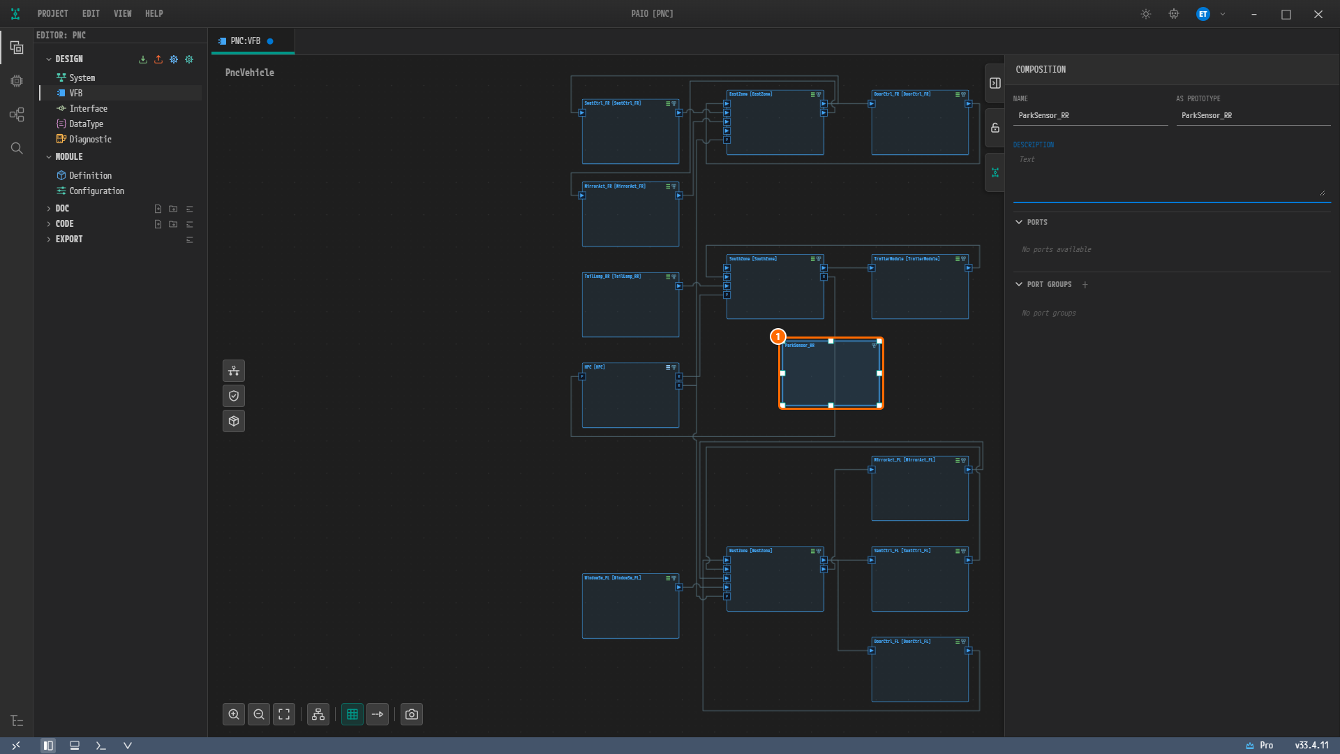
Figure 6-3. The screen after renaming. ① The node. Both NAME and AS PROTOTYPE are
ParkSensor_RR.Caution. Changing NAME does not change AS PROTOTYPE along with it. You must edit both fields. The prototype name at the root and the SWC-ECU mapping both use the AS PROTOTYPE value as their key.
Creating the Atomic SWC
-
Double-click the
ParkSensor_RRnode to drill into it.The path System › ParkSensor_RR appears at the top left of the canvas, together with the empty frame
ParkSensor_RR.Note. The first item of the path is always shown as System, regardless of the root name (
PncVehicle). Click System to return to the root view. -
Right-click inside the frame, hover over Add SWC, and click Application.
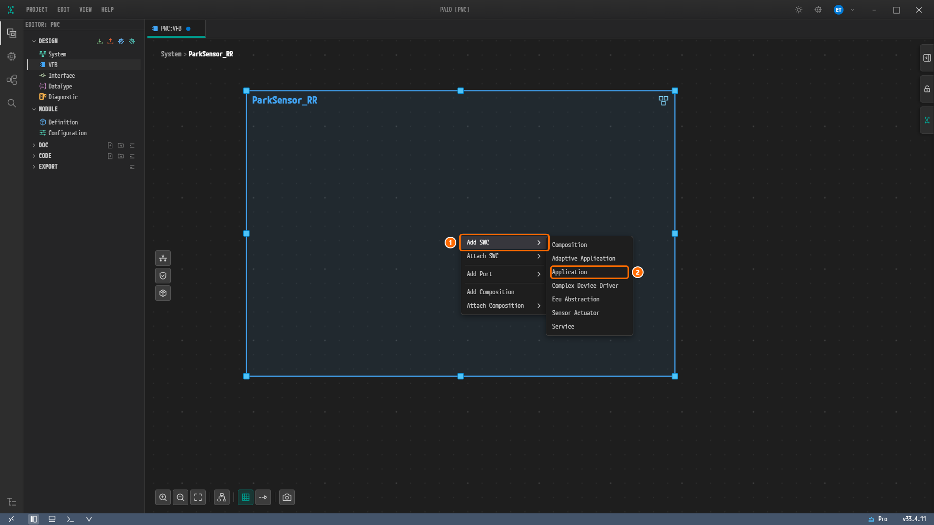
Figure 6-4. Right-clicking inside the frame. ① Add SWC. ② Application, the submenu item to choose. The rest of the submenu is Composition, Adaptive Application, Complex Device Driver, Ecu Abstraction, Sensor Actuator, and Service. This menu does not appear if you right-click the empty canvas outside the frame.
A node appears inside the frame. Its default name is
Application_0. -
Click the new node. The APPLICATION properties panel appears on the right.
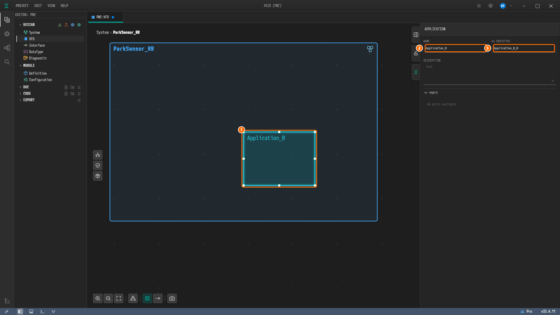
Figure 6-5. The new atomic SWC. ① The node
Application_0inside the frame. ② NAME =Application_0. ③ AS PROTOTYPE =Application_0_0. The two defaults differ. -
Type
ParkDistanceSensingin NAME and press Tab. TypeParkDistanceSensingin AS PROTOTYPE as well and press Tab. Edit both fields, for the same reason as with the composition.
Creating the Ports
You create one port on the SWC and one port on the composition boundary. Both are named ParkDistance and both use the PortInterface SRI_ParkDistance.
-
Right-click near the right edge of the
ParkDistanceSensingnode and choose Add Port › PPort.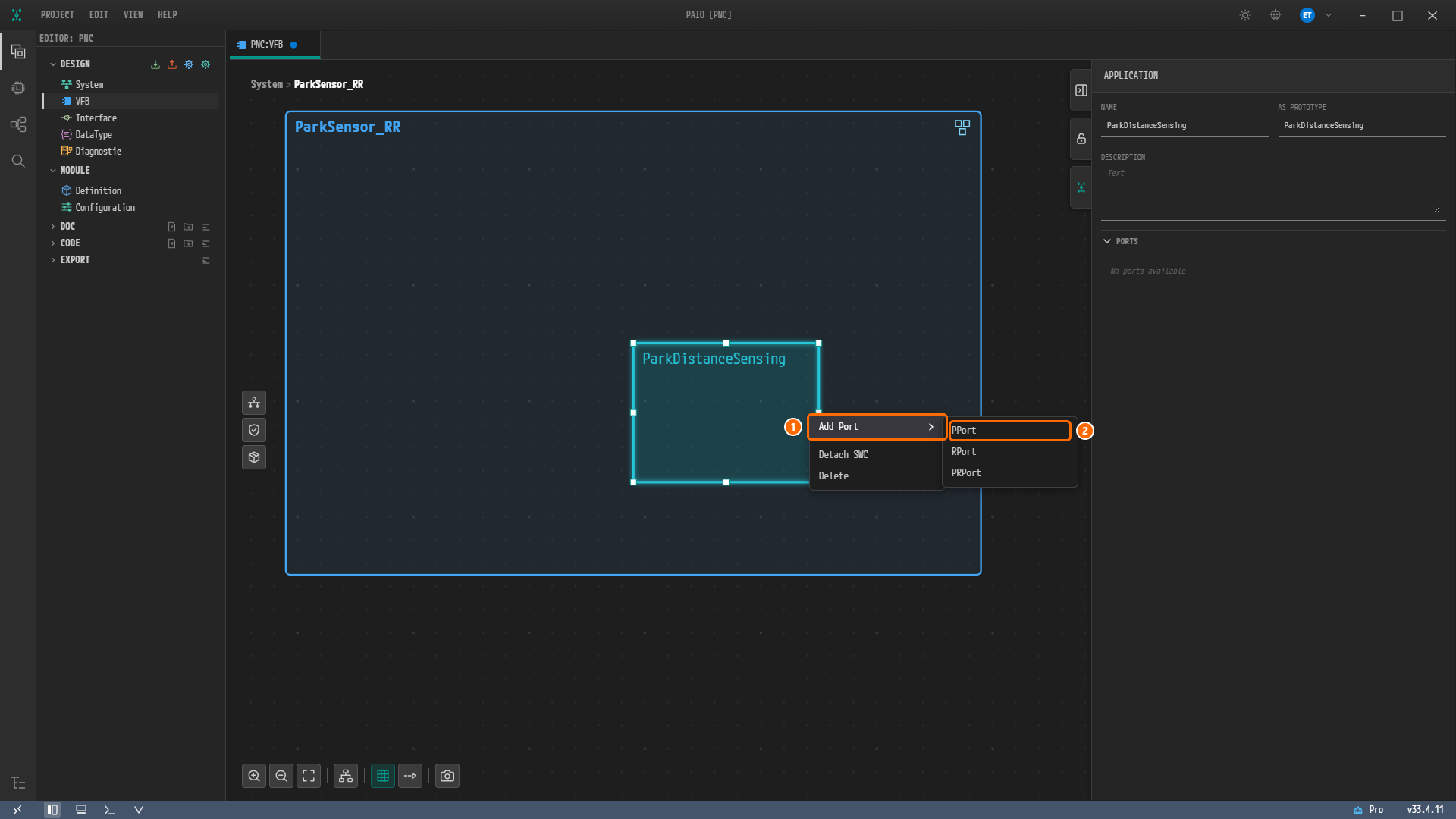
Figure 6-6. Right-clicking the SWC. ① Add Port. ② PPort, the submenu item to choose. The rest of the submenu is RPort and PRPort. The remaining menu items are Detach SWC and Delete.
Note. The port is placed on the edge nearest the point you right-clicked. If you right-click near the node header, the port lands on the top edge and overlaps the name. To place it on the right as in the example, right-click the right edge.
-
Click the new port. The properties panel title changes to PPORT. Type
ParkDistancein NAME, then clickType to search...in PORT INTERFACE and chooseSenderReceiver: SRI_ParkDistancefrom the list.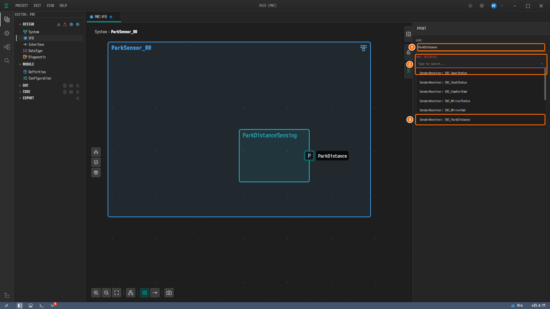
Figure 6-7. Choosing the PortInterface of the port. ① NAME =
ParkDistance. ② The search field of PORT INTERFACE. ③SenderReceiver: SRI_ParkDistance, the item to choose from the list. The list also shows the other SenderReceiver interfaces created in Chapter 5. A port requires a PortInterface, so until you choose one, the PORT INTERFACE label is red and the V icon in the status bar carries the error badge1; once you choose it, the label returns to normal and the badge disappears.Note. While the node is selected, its resize handles overlap the port, so clicking the port selects the node again. Click the empty canvas once to clear the selection, then click the port. If the port is too small to hit, hold Ctrl and scroll the mouse wheel to zoom in. In the drilled-down view, Fit to View fits the frame and its boundary ports to the canvas. An open properties panel covers the right part of the canvas, so if it hides the right edge of the frame, collapse the panel.
-
This time, right-click the right edge of the frame and choose Add Port › PPort. Set the new boundary port to NAME =
ParkDistanceand PORT INTERFACE =SenderReceiver: SRI_ParkDistanceas well.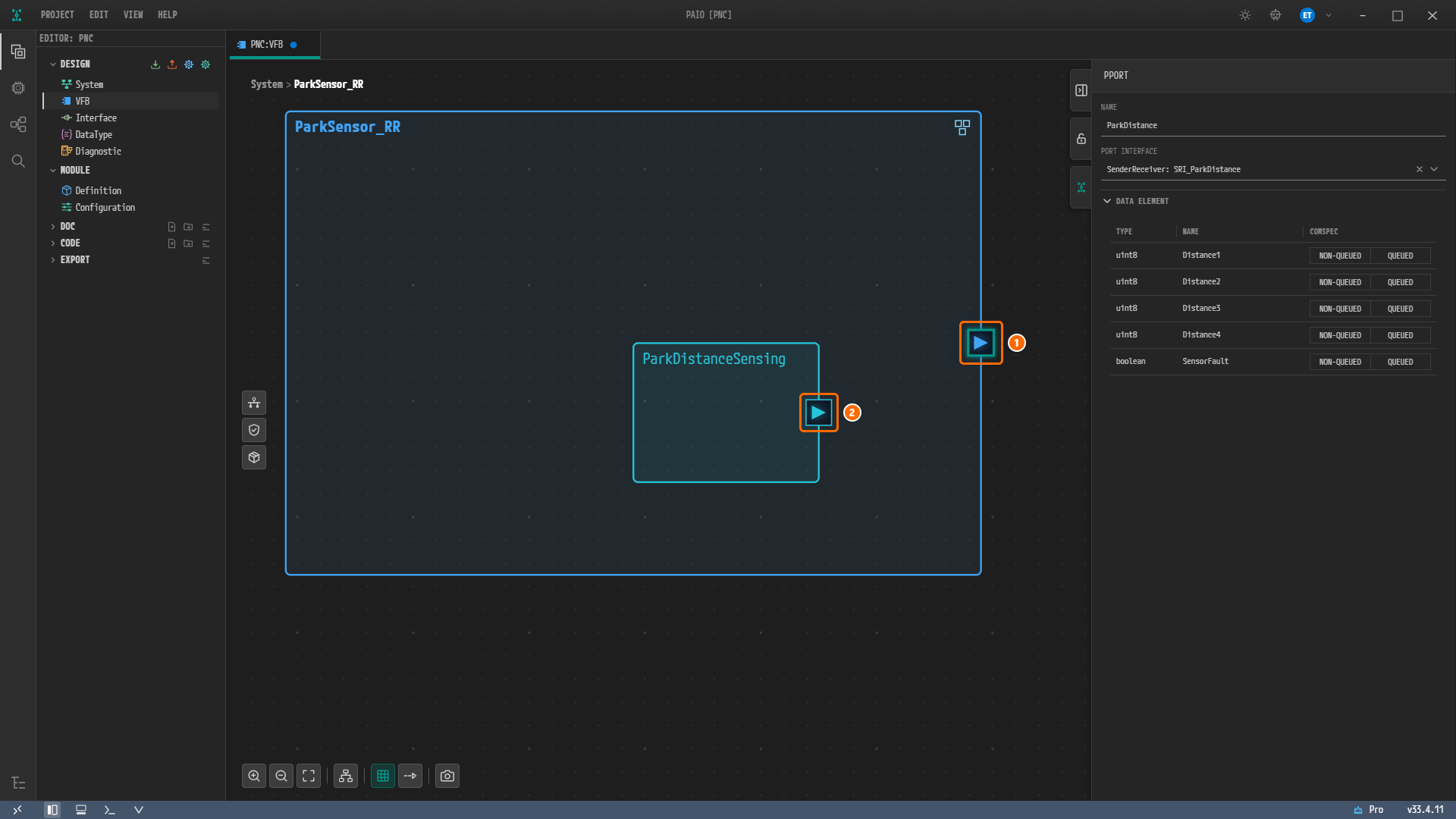
Figure 6-8. Both ports created, not yet connected. ① The composition port created on the frame boundary. ② The SWC port created on
ParkDistanceSensing. On the right, DATA ELEMENT lists the data elements ofSRI_ParkDistance—uint8 Distance1throughDistance4andboolean SensorFault— each with a NON-QUEUED / QUEUED toggle.
Connecting with a Delegation Connector
A connector that joins a composition boundary port to an internal SWC port is called a delegation connector.
-
Right-clicking a port shows Connect to, but on this screen it offers no candidates.
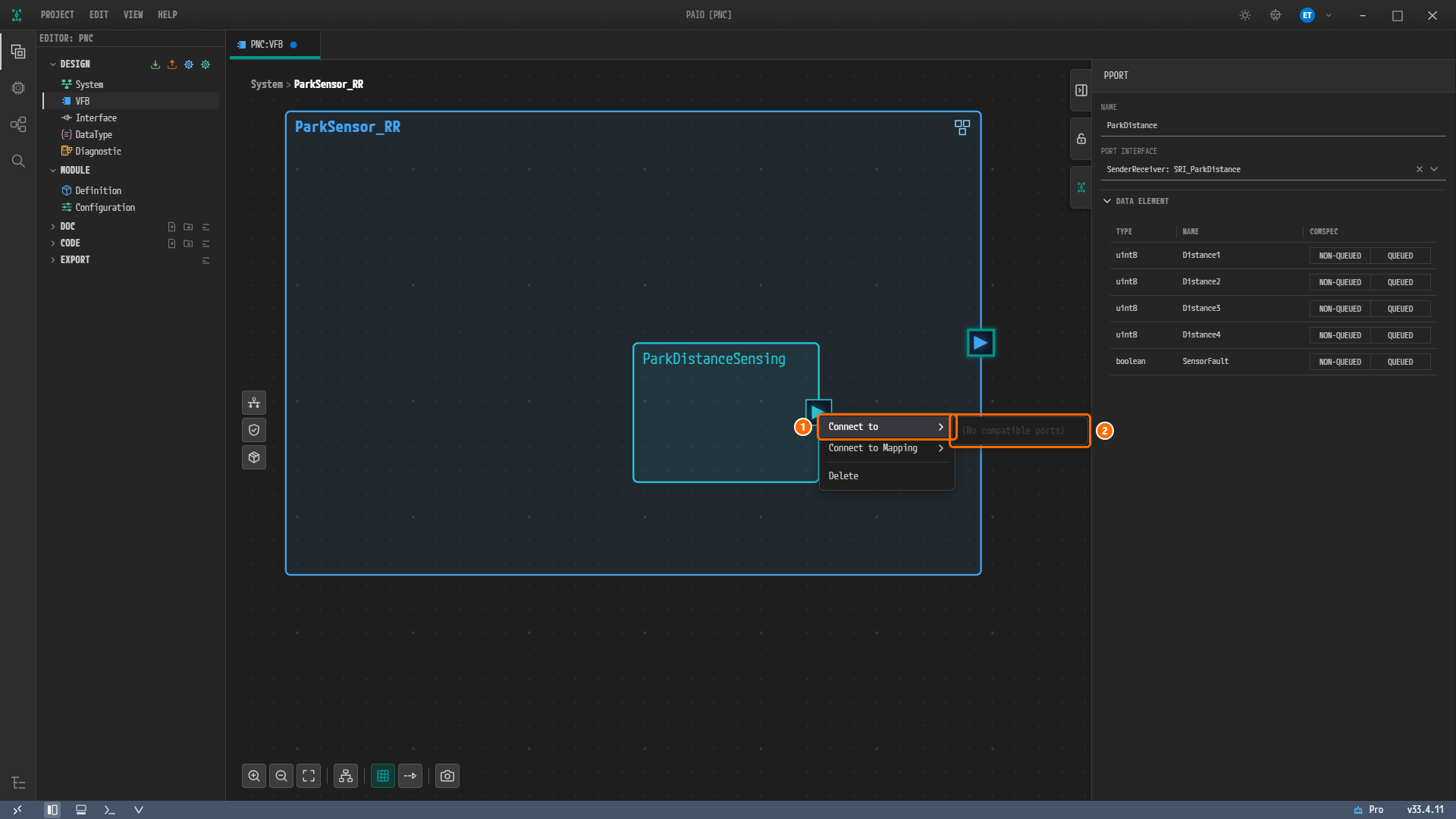
Figure 6-9. Right-clicking the SWC port. ① Connect to. ② The submenu has no candidates and shows only
(No compatible ports). The remaining menu items are Connect to Mapping and Delete.Caution. Connect to is empty even though a boundary port with the same PortInterface exists. In this chapter you connect the ports with Shift+drag instead.
-
Hold Shift and drag the SWC port onto the boundary port.
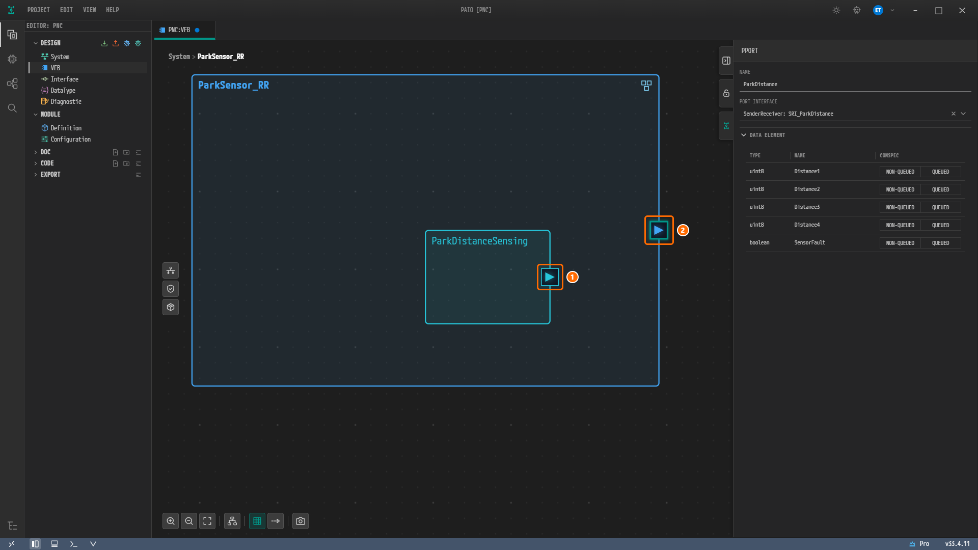
Figure 6-10. Just before the Shift+drag. ① The SWC port where the drag starts. ② The composition boundary port where it ends.
A line is drawn between the two ports.
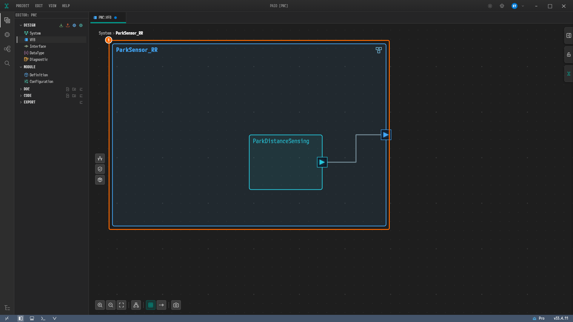
Figure 6-11. The inside of
ParkSensor_RRwith the delegation connector in place, with the properties panel collapsed. ① The frameParkSensor_RR. A line runs from the SWC port to the boundary port.Note. PAIO names the connector automatically, for example
Delegation_ParkDistance_ParkDistanceSensing. You can change the name in NAME on the properties panel after selecting the connector; the meaning of the model does not change.
Connecting with an Assembly Connector
A connector that joins ports of two different compositions is called an assembly connector. You connect ParkDistance (P) of ParkSensor_RR to ParkDistance (R) of SouthZone.
-
Click System in the path to return to the root view.
-
At the root, Connect to offers no candidates either.
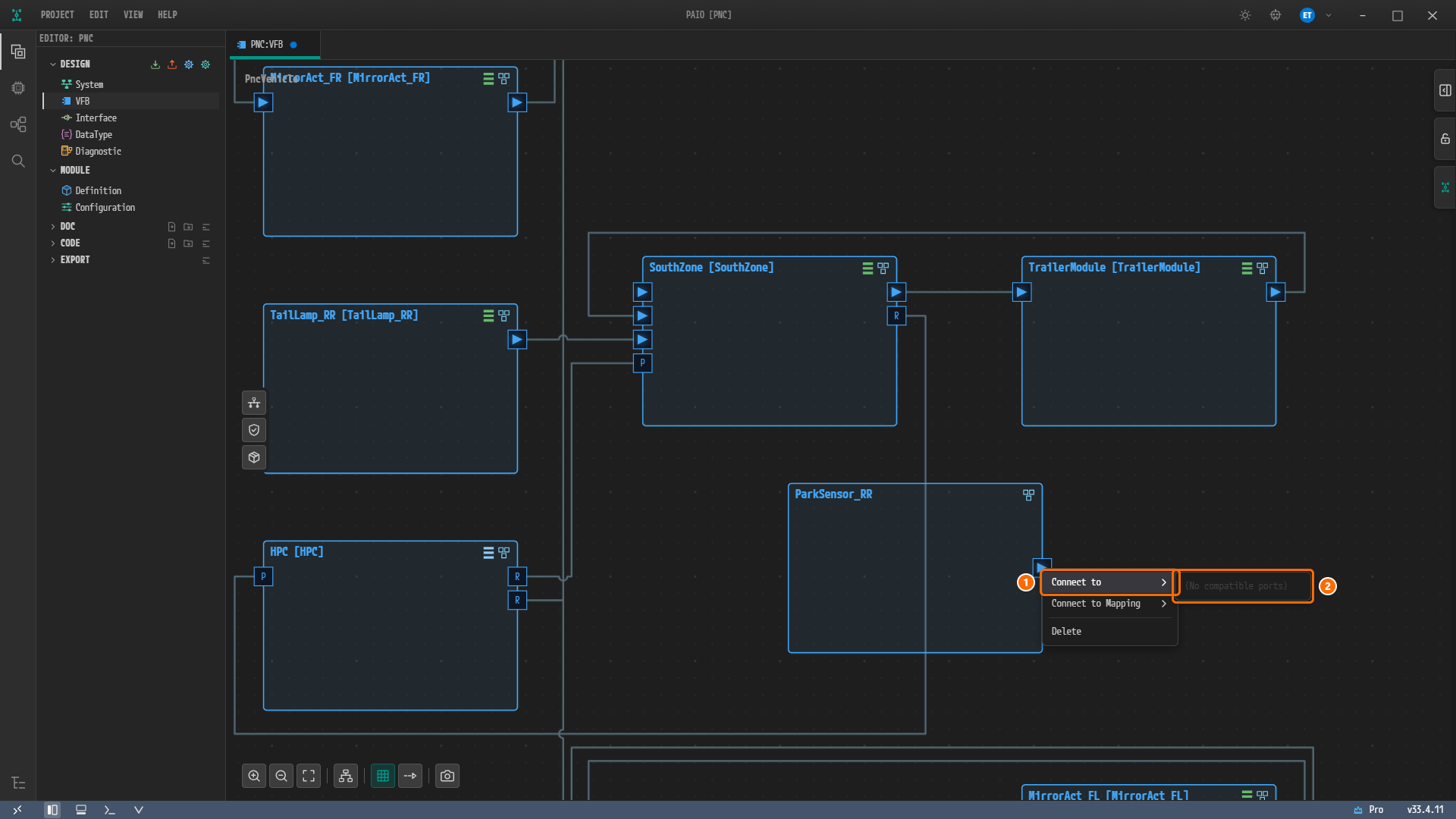
Figure 6-12. Right-clicking the port of
ParkSensor_RRat the root. ① Connect to. ②(No compatible ports)in the submenu. -
Hold Shift and drag the port of
ParkSensor_RRonto theParkDistance(R) port ofSouthZone.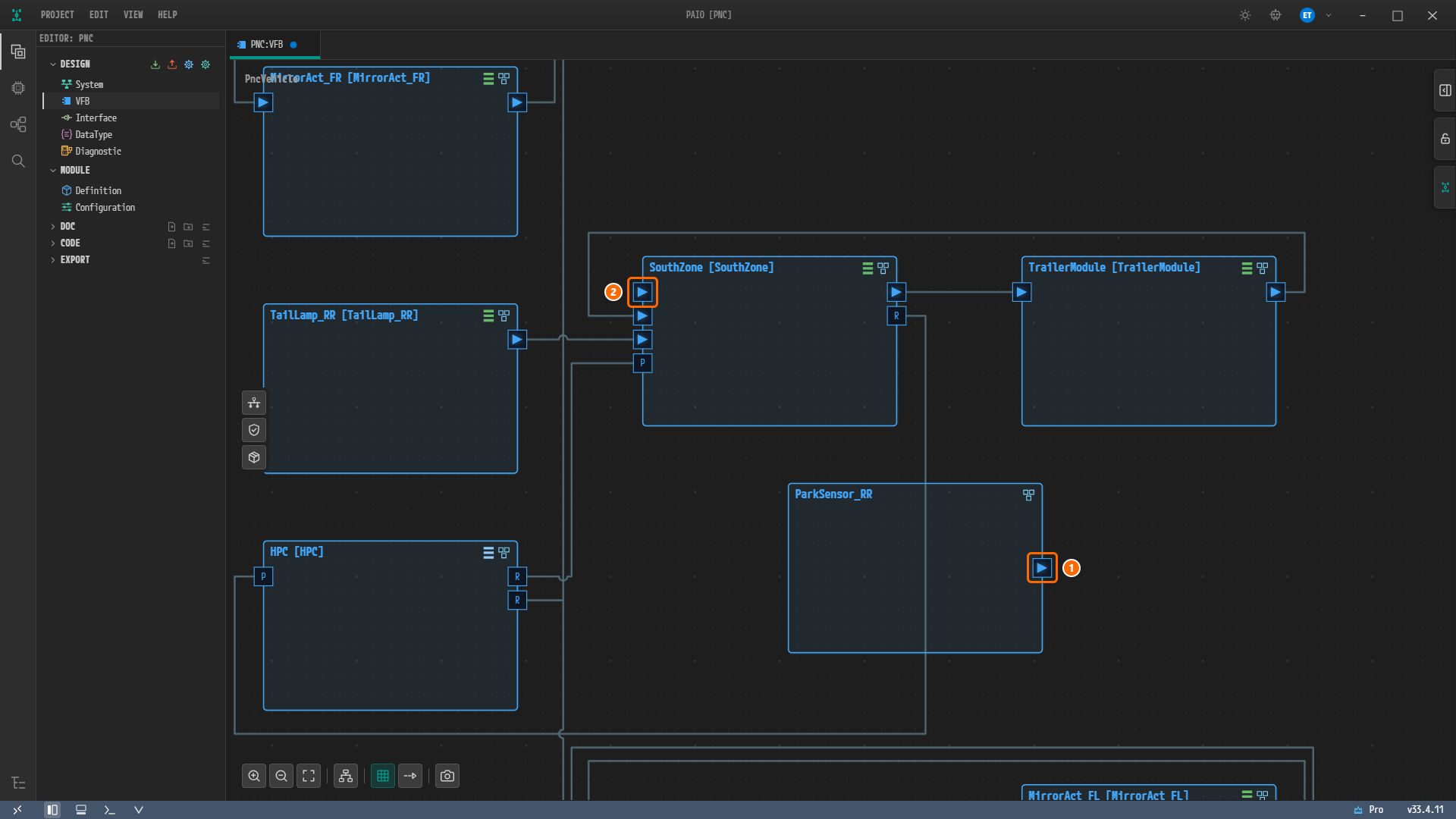
Figure 6-13. Just before the Shift+drag at the root. ① The
ParkDistanceport ofParkSensor_RR, where the drag starts. ② TheParkDistanceport ofSouthZone, where it ends.A line is drawn between the two compositions.
Note. The left edge of
SouthZonecarries several ports side by side, and the canvas does not show their names. If you are not sure which port is which, click a port and check that NAME on the properties panel readsParkDistance.
Mapping to an ECU and Saving
-
At the root, right-click the
ParkSensor_RRnode and choose ECU/HPC Mapping › ParkSensor_RR [ECU].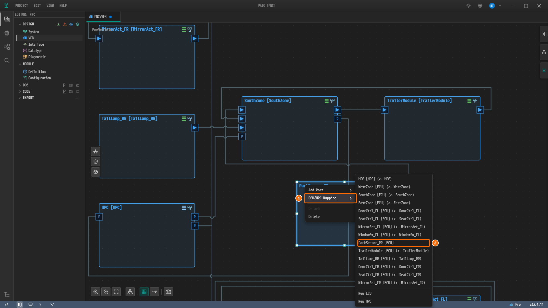
Figure 6-14. Right-clicking a composition node. ① ECU/HPC Mapping. ②
ParkSensor_RR [ECU], the item to choose. A node already mapped to another composition carries that composition name, as inWestZone [ECU] (<- WestZone). At the end of the list are New ECU and New HPC.Note. Right after you map the node, the node header on the canvas shows neither the ECU icon nor the mapped node in brackets; it still reads
ParkSensor_RR. The mapping itself is saved, and once you close and reopen the editor the header shows the ECU icon and readsParkSensor_RR [ParkSensor_RR]. -
Press Ctrl+S to save. The unsaved-change marker on the PNC:VFB tab disappears.
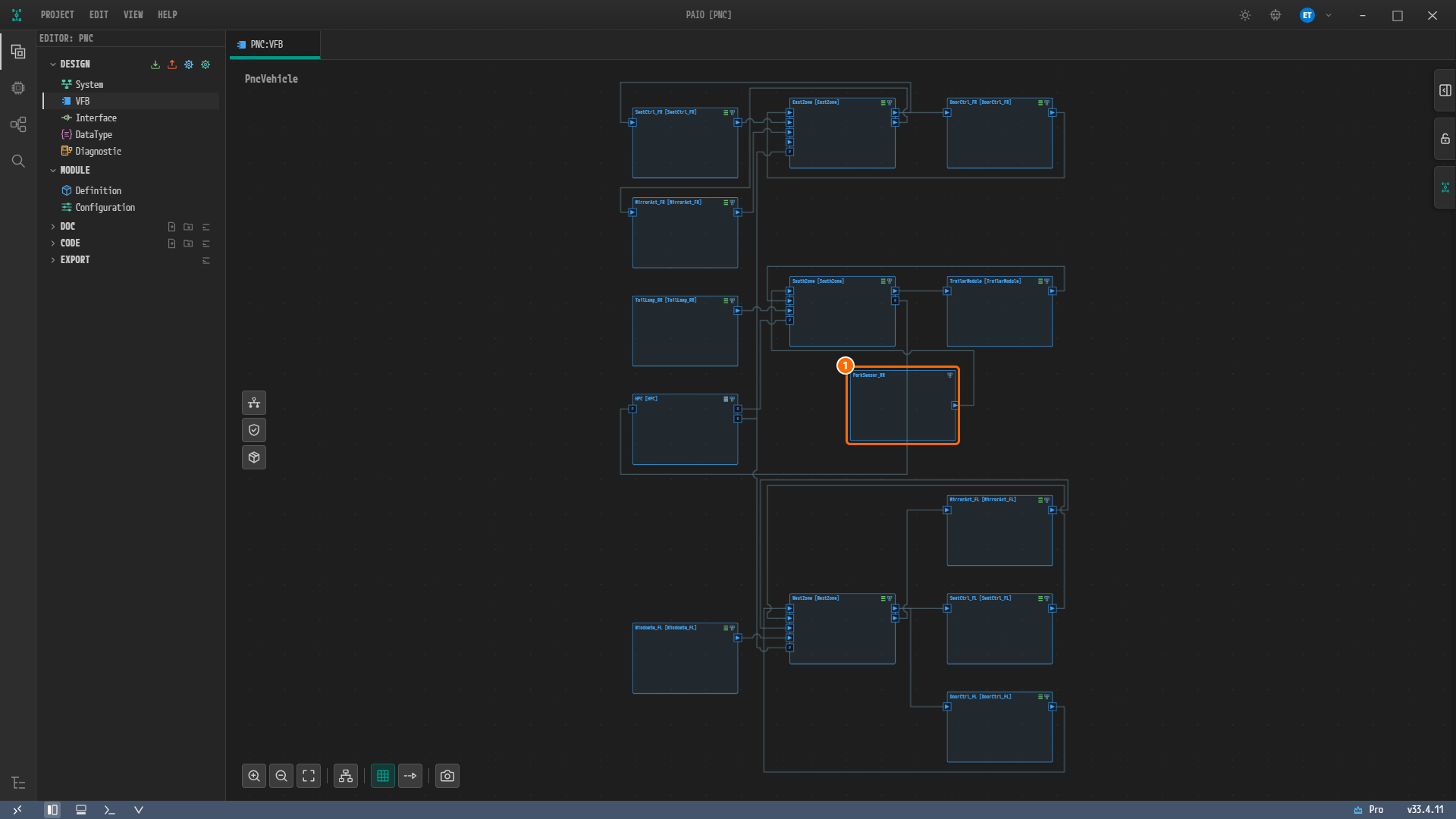
Figure 6-15. The VFB root after saving. ① The composition
ParkSensor_RRcreated in this section. An assembly connector runs from the port on its right edge toSouthZone, and the root now holds 14 compositions in total.
The Remaining 13 Compositions
You create the remaining 13 the same way. Give each composition the same name as the node in the System editor that it maps to, put an atomic SWC inside it, and delegate that SWC port to a boundary port of the same name. After building each composition, map it to the node of the same name with ECU/HPC Mapping.
The representative procedure above assumes that SouthZone already exists. If you are starting from an empty root, create the 13 compositions in the table below first, then return to Creating the SWC and the Composition and build ParkSensor_RR. The next chapter starts from a state in which all 14 are present.
The Internal SWC column of the table uses the form prototype = type. The (P) or (R) on a boundary port is its direction, and the name after it is the PortInterface. Each boundary port is delegated 1:1 to the internal SWC port of the same name.
| Composition (= mapped node) | Node kind | Internal SWC | Composition boundary ports |
|---|---|---|---|
HPC | HPC | ParkAssist = ParkAssistApp, VehicleState = VehicleStateApp, Comfort = ComfortApp | ParkDistanceSvc(R) SVC_ParkDistance, VehicleStateSvc(P) SVC_VehicleState, ComfortControlSvc(R) SVC_ComfortControl |
WestZone | ECU | Gateway = ZoneGateway | ComfortCmd(P) SRI_ComfortCmd, MirrorCmd(P) SRI_MirrorCmd, DoorStatus(R) SRI_DoorStatus, SeatStatus(R) SRI_SeatStatus, MirrorStatus(R) SRI_MirrorStatus, WindowSwitch(R) SRI_WindowSwitch, ComfortControlSvc(P) SVC_ComfortControl |
EastZone | ECU | Gateway = ZoneGateway | Same as WestZone |
SouthZone | ECU | Gateway = RearGateway | ParkDistance(R) SRI_ParkDistance, TrailerStatus(R) SRI_TrailerStatus, TrailerCmd(P) SRI_TrailerCmd, TailLamp(R) SRI_TailLamp, ParkDistanceSvc(P) SVC_ParkDistance, VehicleStateSvc(R) SVC_VehicleState |
DoorCtrl_FL, DoorCtrl_FR | ECU | DoorControl = DoorControl | DoorStatus(P) SRI_DoorStatus, ComfortCmd(R) SRI_ComfortCmd |
SeatCtrl_FL, SeatCtrl_FR | ECU | SeatControl = SeatControl | SeatStatus(P) SRI_SeatStatus, ComfortCmd(R) SRI_ComfortCmd |
MirrorAct_FL, MirrorAct_FR | ECU | MirrorControl = MirrorControl | MirrorStatus(P) SRI_MirrorStatus, MirrorCmd(R) SRI_MirrorCmd |
WindowSw_FL | ECU | WindowSwitch = WindowSwitch | WindowSwitch(P) SRI_WindowSwitch |
ParkSensor_RR | ECU | ParkDistanceSensing = ParkDistanceSensing | ParkDistance(P) SRI_ParkDistance (created in this chapter) |
TrailerModule | ECU | TrailerControl = TrailerControl | TrailerStatus(P) SRI_TrailerStatus, TrailerCmd(R) SRI_TrailerCmd |
TailLamp_RR | ECU | TailLampControl = TailLampControl | TailLamp(P) SRI_TailLamp |
The three internal SWCs of HPC are Adaptive Applications, not atomic SWCs, so you create them with Adaptive Application under Add SWC. HPC later receives one more composition prototype, PARA. You do not create it yourself — the PARA Platform Import in PARA Platform Import and PNC Request Ports adds it for you.
The root PncVehicle has 21 assembly connectors in total. They connect the status ports (P) of the end ECUs to a Zone (R), the command ports (P) of a Zone to the end ECUs (R), and the service ports of a Zone to the HPC. Inside HPC there is one more assembly connector, between VehicleStateSvc of VehicleState and VehicleStateSvc of ParkAssist.
Note. To generate code, an atomic SWC needs a runnable and RTE events. In the finished example,
ParkDistanceSensinghas the runnableParkDistanceSensing_Mainand the timing eventTE_ParkDistanceSensing_Mainwith a cycle time of0.05. This tutorial targets PNC design, so it does not cover internal behavior. See VFB Editor for how to create it.
Reviewing the VFB Root Structure
-
Arrange the root again once all 14 compositions are in place. Click Auto Layout, and click Fit to View if the whole layout does not fit on screen.
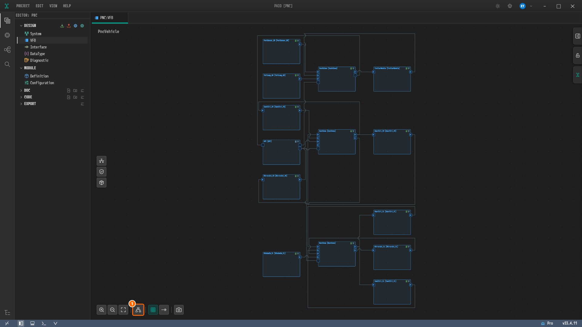
Figure 6-16. The VFB root
PncVehiclewith Auto Layout applied. ① The Auto Layout button. The canvas shows the 14 compositions and the assembly connectors between them. Auto Layout repositions all 14, so the layout differs from the hand-placed one in Figure 6-15 (ParkSensor_RRmoves to the top left). Node names are small when the window shows the whole root, so zoom in with Ctrl and the mouse wheel to read them, as in Figure 6-25 later in this chapter.
The root PncVehicle is structured by the following rules.
- One composition per node. Each node in the System editor (HPC, ECU) gets one composition. The atomic SWCs live inside that composition.
- Composition name = node name. Give each composition the same name as its node in the System editor. The VFB uses the composition's prototype name (AS PROTOTYPE) to find the SWC-ECU mapping and link the composition to a node (machine).
- SWC-ECU mapping. The SWC-ECU mapping in the SYSTEM places each composition on the node of the same name. The ECU/HPC Mapping command from the previous section creates this mapping.
- Assembly connectors. The status ports of an end ECU connect to a Zone, and the command ports of a Zone connect to the end ECUs. The service ports of a Zone connect to the HPC.
A composition node on the canvas shows its name followed by the node it is mapped to in brackets, for example EastZone [EastZone]; a composition that is not mapped shows its name alone. The compositions of the example and their mapping targets are as follows.
| Composition (= mapped node) | Role |
|---|---|
HPC | HPC (AP). Hosts the application AAs |
WestZone, EastZone, SouthZone | Zone ECUs. Host the gateway SWCs |
DoorCtrl_FL, SeatCtrl_FL, MirrorAct_FL, WindowSw_FL, DoorCtrl_FR, SeatCtrl_FR, MirrorAct_FR | Comfort end ECUs |
ParkSensor_RR | Park distance sensor end ECU |
TrailerModule, TailLamp_RR | Trailer end ECUs |
Note. To review or change a mapping, right-click the composition node at the root and use ECU/HPC Mapping. See the composition node menu in VFB Editor for details.
VFC and PortGroup
In AUTOSAR a VFC (Virtual Function Cluster) is realized as a PortGroup. This tutorial follows these conventions.
- Collect the ports that participate in one function — park assist, for example — into a single PortGroup.
- Name the PortGroup
VFC_<function>:VFC_Comfort,VFC_ParkAssist,VFC_Trailer. - Set the CATEGORY of every PortGroup to
PARTIAL_NETWORKING.
The VFC Family Rule
The PortGroups that belong to the same VFC use the same name at every level of the hierarchy. This set is called a VFC family. For VFC_ParkAssist it looks like this.
| Level | Example | PortGroup name | Contents |
|---|---|---|---|
| Atomic SWC | ParkDistanceSensing | VFC_ParkAssist | OUTER PORTS = ParkDistance |
| ECU composition | ParkSensor_RR | VFC_ParkAssist | OUTER PORTS = the delegated port ParkDistance, INNER GROUPS = ParkDistanceSensing / VFC_ParkAssist |
| Root composition | PncVehicle | VFC_ParkAssist | INNER GROUPS = VFC_ParkAssist of the participating direct prototypes HPC, SouthZone, and ParkSensor_RR |
- OUTER PORTS: the ports of that SWC (or composition) that participate in this VFC.
- INNER GROUPS: references to the PortGroup of the same name on a prototype inside the composition.
Caution. If you give a lower-level PortGroup a different name, such as
PG_ParkAssist, it is not recognized as a VFC member. The VFC table in the PNC Dialog counts only those direct prototypes of the root that "have a PortGroup with the same name as the VFC" as members. Always use the same name.
Creating a PortGroup
As the representative case, you create VFC_ParkAssist on the atomic SWC ParkDistanceSensing you built earlier.
-
On the root canvas, double-click the
ParkSensor_RRcomposition.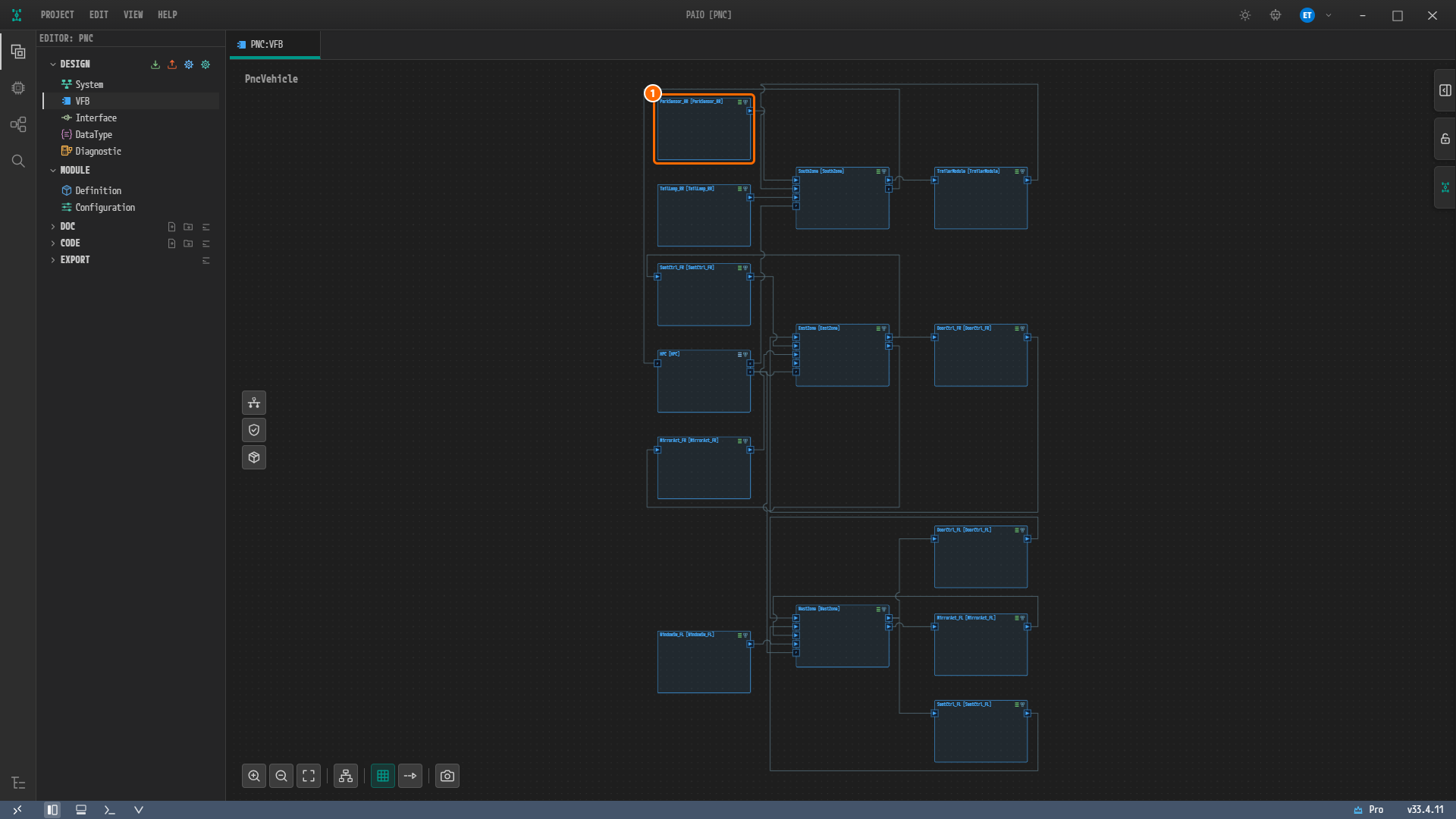
Figure 6-17. The VFB root. ① The
ParkSensor_RRcomposition to double-click (top left after Auto Layout).You drill into the composition. The path System › ParkSensor_RR appears at the top left of the canvas, and the atomic SWC
ParkDistanceSensingis visible inside the frameParkSensor_RR. -
Click Fit to View on the toolbar at the bottom of the canvas. Whether the frame first appears larger than the view or small, Fit to View fits the frame and its boundary ports on screen.
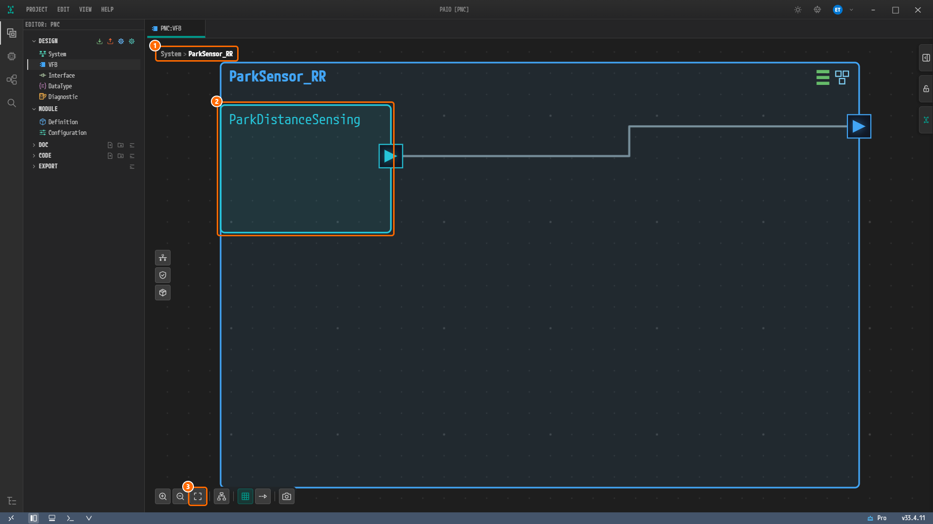
Figure 6-18. Drilled down into
ParkSensor_RR, after Fit to View. ① The path System › ParkSensor_RR. ② The atomic SWCParkDistanceSensing. ③ Fit to View on the canvas toolbar. The SWC portParkDistanceis delegated to the port on the frame boundary. -
Double-click
ParkDistanceSensing.The SWC Internal Behavior [ParkDistanceSensing] dialog opens.
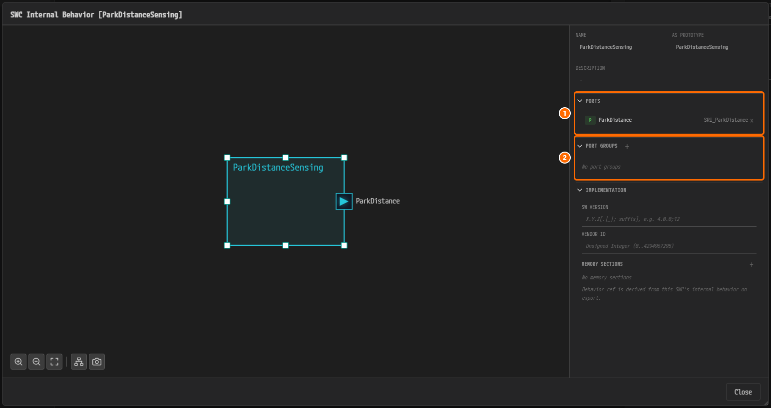
Figure 6-19. The SWC Internal Behavior [ParkDistanceSensing] dialog. ① PORTS holds the
PParkDistance(SRI_ParkDistance) you created earlier. ② PORT GROUPS still readsNo port groups. The IMPLEMENTATION section below it (SW VERSION, VENDOR ID, MEMORY SECTIONS) is not used in this chapter. -
Click the + (tooltip
Add Port Group) to the right of the PORT GROUPS header.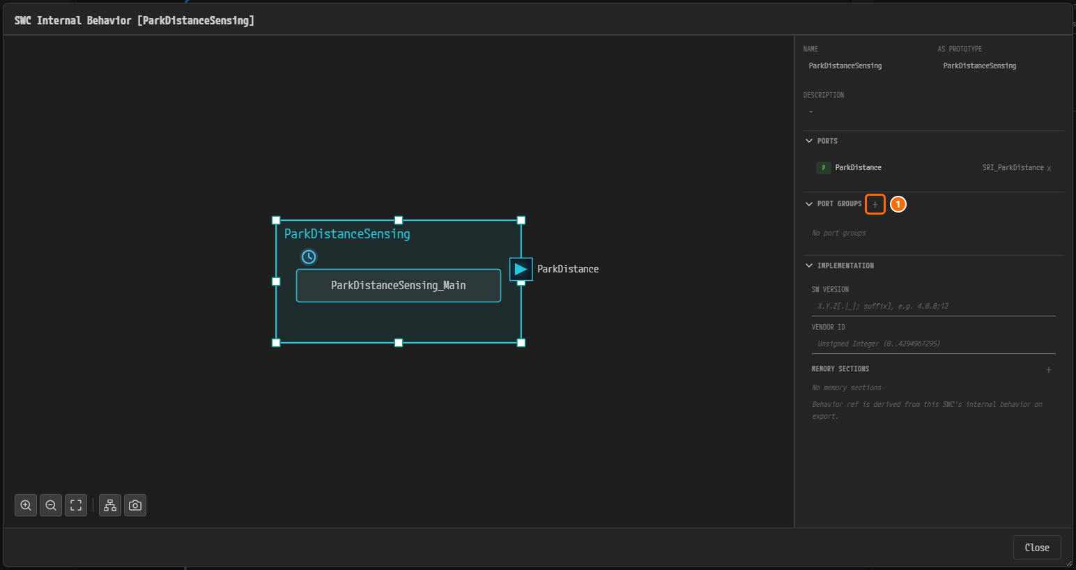
Figure 6-20. The right panel of the same dialog. ① The + button of PORT GROUPS, the button to click. The state is still
No port groups.Note. Figures 6-20 through 6-22 are from the finished example, so the canvas on the left also shows a runnable box (
ParkDistanceSensing_Main) and a clock icon that stands for a timing event. The SWC you built by following this chapter has no internal behavior, so the SWC box on your canvas is empty, as in Figure 6-19. This section uses only the right panel, so the result is the same.A new PortGroup block,
PortGroup_0, appears. -
In NAME on the block, delete the default name
PortGroup_0, typeVFC_ParkAssist, and press Tab. The block title changes toVFC_ParkAssist. -
In CATEGORY, click PARTIAL_NETWORKING. The other choice is MODE_MANAGEMENT.
-
Click the + (tooltip
Add member port (pick a port to commit)) to the right of the OUTER PORTS header.A new row
1appears. Its PORT field stays empty and underlined in red (tooltipRequired) until you pick a port. -
Click the ▾ button at the right of the row to open the candidate list and choose
ParkDistance. The only candidates are the ports of this SWC itself.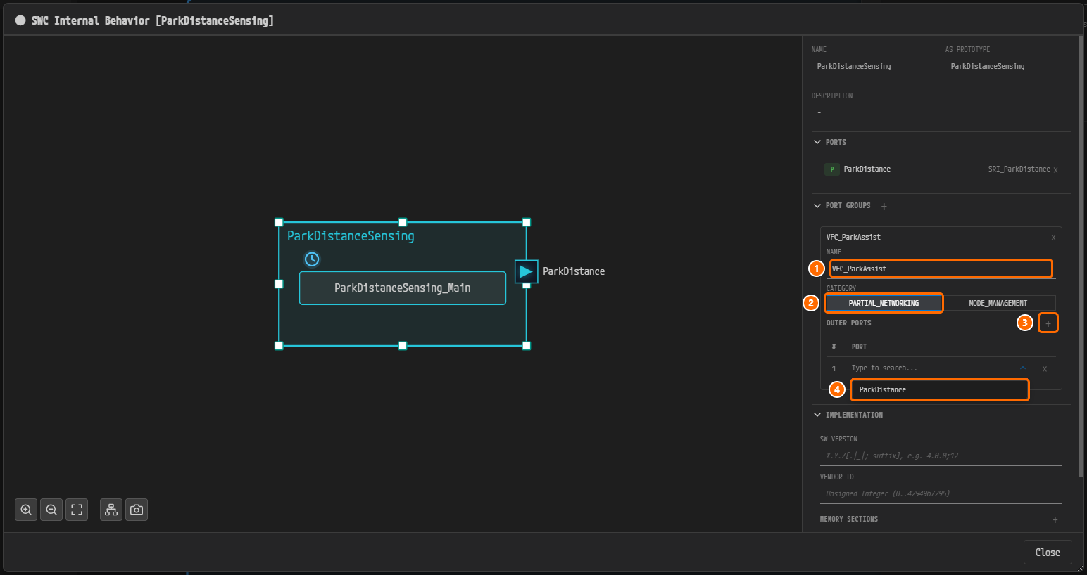
Figure 6-21. Filling in the PortGroup. ① NAME =
VFC_ParkAssist. ② PARTIAL_NETWORKING in CATEGORY. ③ The + of OUTER PORTS. ④ The dropdown candidateParkDistance. The ● marker in front of the dialog title means there are unsaved changes.The row changes to
1 | ParkDistance.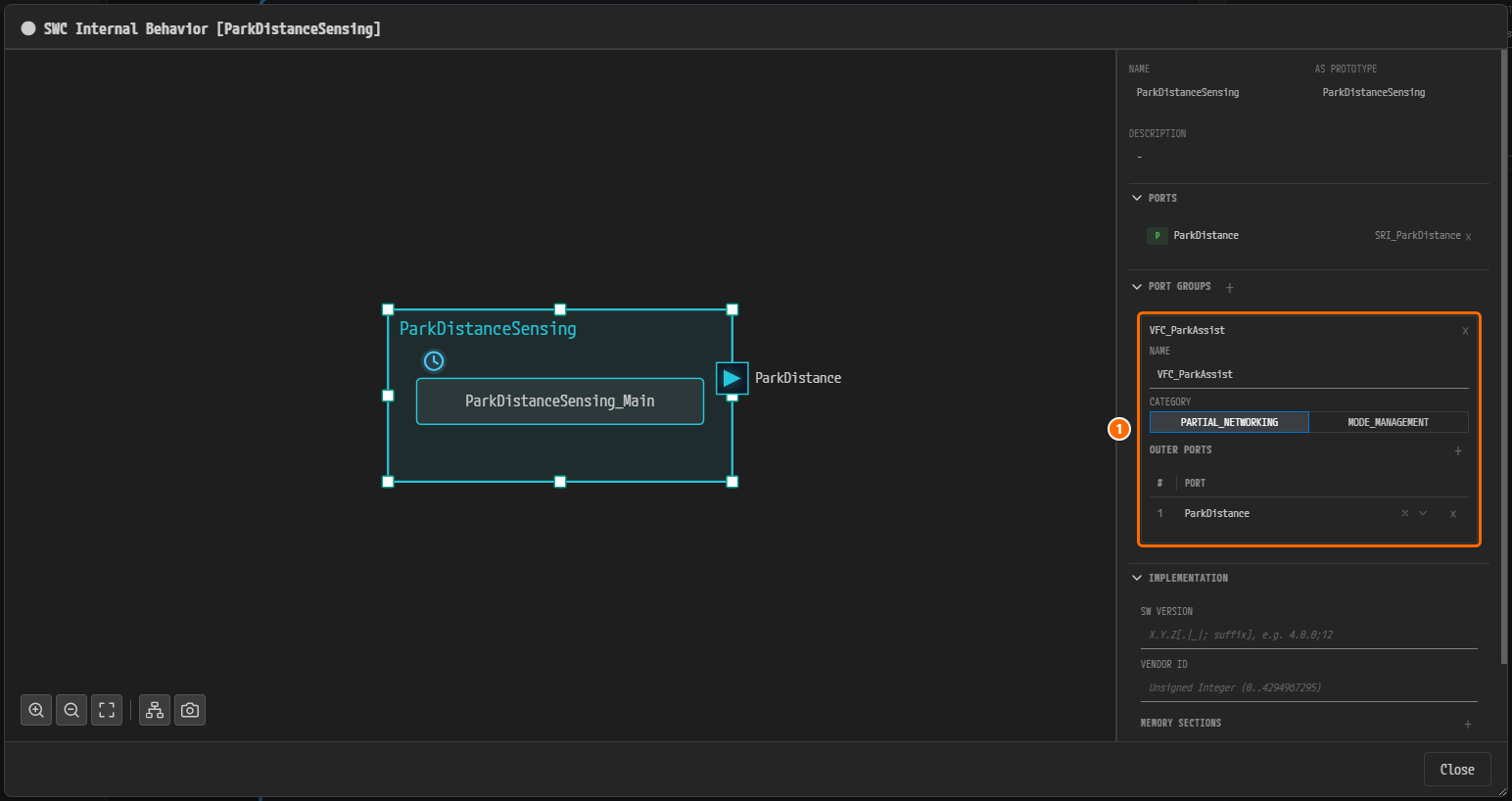
Figure 6-22. The finished PortGroup block, before saving. ① The whole block — NAME
VFC_ParkAssist, CATEGORY PARTIAL_NETWORKING (with the unselected MODE_MANAGEMENT on the right), and one OUTER PORTS row,ParkDistance. The Close button sits at the bottom right of the dialog. -
Press Ctrl+S to save the dialog. The ● marker in front of the title disappears.
-
Click Close at the bottom right to close the dialog.
-
Press Ctrl+S again in the VFB editor to save. The unsaved-change marker on the PNC:VFB tab disappears.
When you save, PAIO automatically creates a PortGroup of the same name on the parent compositions.
| Composition | PortGroup created automatically |
|---|---|
ParkSensor_RR | VFC_ParkAssist, INNER GROUPS = ParkDistanceSensing / VFC_ParkAssist |
PncVehicle (root) | VFC_ParkAssist, INNER GROUPS = ParkSensor_RR / VFC_ParkAssist |
Checking the Automatically Created PortGroup
-
In the drilled-down view, click the title row of the
ParkSensor_RRframe (the row that carries the nameParkSensor_RR).The COMPOSITION properties panel appears on the right.
-
Look at PORT GROUPS on the properties panel.
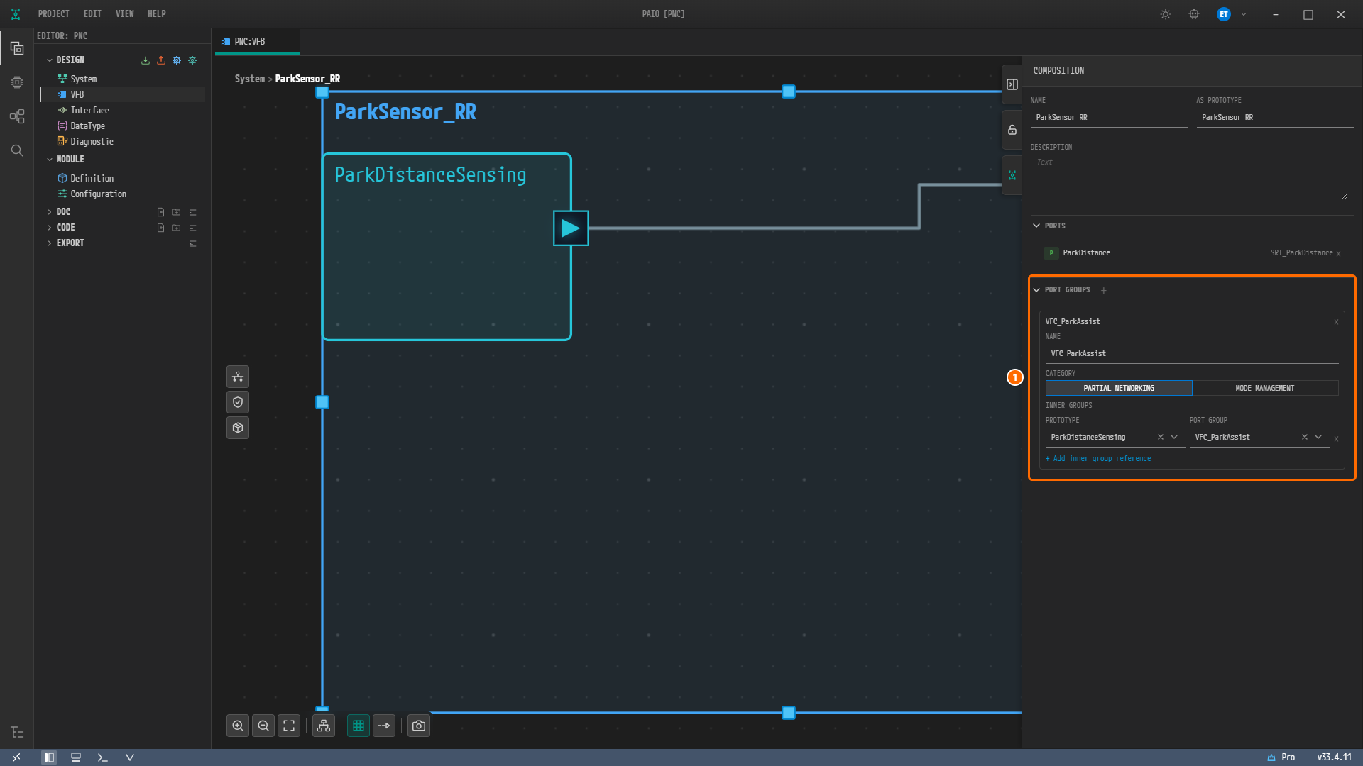
Figure 6-23.
ParkSensor_RRselected after saving. ① The automatically createdVFC_ParkAssistin PORT GROUPS. CATEGORY is PARTIAL_NETWORKING, and under INNER GROUPS the PROTOTYPE isParkDistanceSensingand the PORT GROUP isVFC_ParkAssist. Use+ Add inner group referencebelow to add more inner group references.
Note. An automatically created composition PortGroup does not get its OUTER PORTS (the delegated ports) filled in. So the
ParkSensor_RRyou built by following this chapter has only INNER GROUPS, whereas theParkSensor_RRof the finished example also has the OUTER PORTSParkDistance(see the VFC family table above). The PORT GROUPS section of the composition properties panel lets you edit only INNER GROUPS, and the application AAs (ComfortApp,ParkAssistApp,VehicleStateApp) have no screen for editing PortGroups at all. The member ports of compositions and application AAs are covered in PNC Dialog — Per-PNC Binding.
The Remaining PortGroups
There are 33 PortGroups in total, and the CATEGORY of every one is PARTIAL_NETWORKING. Create the rest the same way, following the tables below.
- PortGroups on atomic SWCs follow the procedure above. Double-click the SWC to open the SWC Internal Behavior dialog, create the group with the + of PORT GROUPS, and fill in OUTER PORTS.
- PortGroups on ECU compositions and on the root are created automatically with the same name when you save the PortGroup of an atomic SWC, and their INNER GROUPS are filled in at the same time.
- The OUTER PORTS of ECU compositions and application AAs cannot be edited in the VFB editor. An automatically created composition PortGroup has empty OUTER PORTS. You fill these in with the SWC HIERARCHY checkboxes in the next chapter, PNC Dialog — Per-PNC Binding. The OUTER PORTS columns of the two tables below are also the list of ports to check there.
- The application AAs (
ComfortApp,ParkAssistApp,VehicleStateApp) have no screen for creating a PortGroup at all. You create the PortGroups of these three in SWC HIERARCHY as well.
Atomic SWCs and application AAs (OUTER PORTS)
| SWC | PortGroup | OUTER PORTS |
|---|---|---|
DoorControl | VFC_Comfort | DoorStatus, ComfortCmd |
SeatControl | VFC_Comfort | SeatStatus, ComfortCmd |
MirrorControl | VFC_Comfort | MirrorStatus, MirrorCmd |
WindowSwitch | VFC_Comfort | WindowSwitch |
ZoneGateway | VFC_Comfort | ComfortCmd, MirrorCmd, DoorStatus, SeatStatus, MirrorStatus, WindowSwitch, ComfortControlSvc |
ParkDistanceSensing | VFC_ParkAssist | ParkDistance (created in this chapter) |
RearGateway | VFC_ParkAssist | ParkDistance, ParkDistanceSvc |
RearGateway | VFC_Trailer | TrailerStatus, TrailerCmd, TailLamp, VehicleStateSvc |
TrailerControl | VFC_Trailer | TrailerStatus, TrailerCmd |
TailLampControl | VFC_Trailer | TailLamp |
ComfortApp (AA) | VFC_Comfort | ComfortControlSvc |
ParkAssistApp (AA) | VFC_ParkAssist | ParkDistanceSvc, VehicleStateSvc |
VehicleStateApp (AA) | VFC_Trailer | VehicleStateSvc |
ECU compositions (OUTER PORTS + INNER GROUPS)
| Composition | PortGroup | OUTER PORTS | INNER GROUPS (PROTOTYPE / PORT GROUP) |
|---|---|---|---|
DoorCtrl_FL, DoorCtrl_FR | VFC_Comfort | DoorStatus, ComfortCmd | DoorControl / VFC_Comfort |
SeatCtrl_FL, SeatCtrl_FR | VFC_Comfort | SeatStatus, ComfortCmd | SeatControl / VFC_Comfort |
MirrorAct_FL, MirrorAct_FR | VFC_Comfort | MirrorStatus, MirrorCmd | MirrorControl / VFC_Comfort |
WindowSw_FL | VFC_Comfort | WindowSwitch | WindowSwitch / VFC_Comfort |
WestZone, EastZone | VFC_Comfort | ComfortCmd, MirrorCmd, DoorStatus, SeatStatus, MirrorStatus, WindowSwitch, ComfortControlSvc | Gateway / VFC_Comfort |
ParkSensor_RR | VFC_ParkAssist | ParkDistance | ParkDistanceSensing / VFC_ParkAssist |
SouthZone | VFC_ParkAssist | ParkDistance, ParkDistanceSvc | Gateway / VFC_ParkAssist |
SouthZone | VFC_Trailer | TrailerStatus, TrailerCmd, TailLamp, VehicleStateSvc | Gateway / VFC_Trailer |
TrailerModule | VFC_Trailer | TrailerStatus, TrailerCmd | TrailerControl / VFC_Trailer |
TailLamp_RR | VFC_Trailer | TailLamp | TailLampControl / VFC_Trailer |
HPC | VFC_ParkAssist | ParkDistanceSvc | ParkAssist / VFC_ParkAssist |
HPC | VFC_Comfort | ComfortControlSvc | Comfort / VFC_Comfort |
HPC | VFC_Trailer | VehicleStateSvc | VehicleState / VFC_Trailer |
The root PncVehicle (INNER GROUPS only, created automatically when the VFB is saved)
| PortGroup | Participating direct prototypes |
|---|---|
VFC_Comfort | HPC, WestZone, EastZone, DoorCtrl_FL, SeatCtrl_FL, MirrorAct_FL, WindowSw_FL, DoorCtrl_FR, SeatCtrl_FR, MirrorAct_FR (10) |
VFC_ParkAssist | HPC, SouthZone, ParkSensor_RR (3) |
VFC_Trailer | HPC, SouthZone, TrailerModule, TailLamp_RR (4) |
Checking VFCs with the PNC Overlay
PortGroups are not drawn on the canvas. To see which compositions participate in each VFC, use the VFC (PNC Overlay) icon.
-
If you are in the drilled-down view, click System in the path to return to the root view.
-
Collapse the properties panel if it is open, and click Fit to View to bring the whole root into view.
-
In the vertical icon strip along the left edge of the canvas, click the first icon, VFC (PNC Overlay). The two icons below it, Intrusion Detection System and Software Cluster, open dialogs that this chapter does not use.
The PNC OVERLAY panel opens at the top left of the canvas. The VFC list on the panel is sorted by name, and the first item is selected by default. The compositions that do not participate in the selected VFC are dimmed.
Figure 6-24 was captured at the point where only
VFC_ParkAssistonParkDistanceSensinghad been created. At that point there is a single VFC, so the list shows one button and that button is selected immediately. On the canvas, onlyParkSensor_RRappears normally, and the other 13 compositions are dimmed. No PNC references this VFC yet, so BOUND PNCS shows--.Once you have created everything in the tables under The Remaining PortGroups, the list shows three entries —
VFC_Comfort,VFC_ParkAssist, andVFC_Trailer— and the screen matches The Overlay in the Finished Example.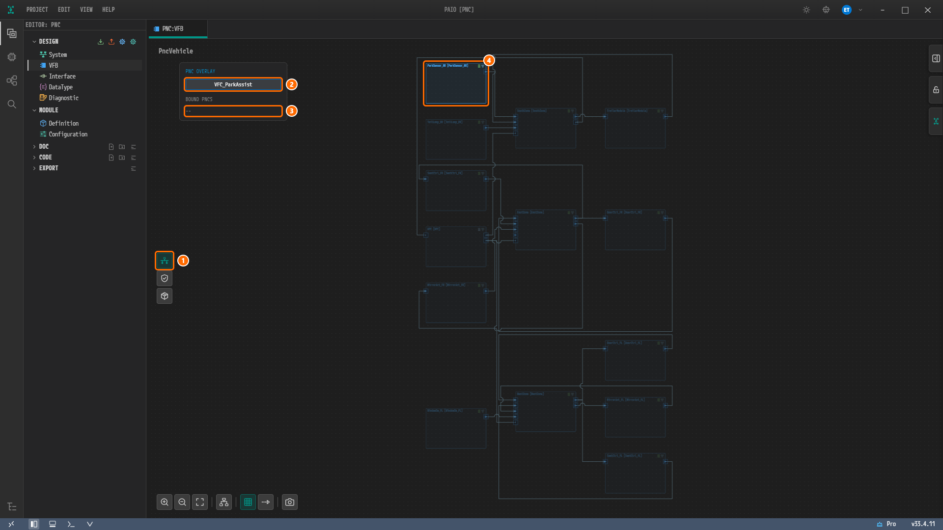
Figure 6-24. The overlay turned on in a project built by following this chapter. ① The first icon in the vertical icon strip, VFC (PNC Overlay) (turned on). ②
VFC_ParkAssist, the only button in the VFC list (selected). ③ BOUND PNCS =--. ④ParkSensor_RR, which participates in this VFC. The other 13 compositions are dimmed. -
If the node names are too small to read, hold Ctrl and scroll the mouse wheel to zoom in.
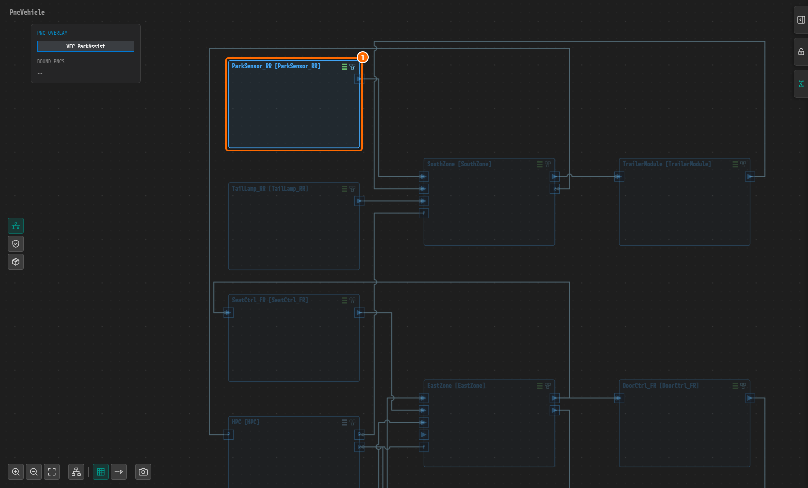
Figure 6-25. The screen of Figure 6-24, zoomed in around
ParkSensor_RR. ①ParkSensor_RR, shown normally. Its neighborsTailLamp_RR,SouthZone,TrailerModule,SeatCtrl_FR,HPC,EastZone, andDoorCtrl_FRare dimmed. -
To turn the overlay off, click the VFC (PNC Overlay) icon again.
The Overlay in the Finished Example
In the finished example, where all 33 PortGroups are present and the PNC binding is complete, the overlay looks as follows. Because PortGroups are not drawn on the canvas, the root view of the finished example has the same shape as Figure 6-16.
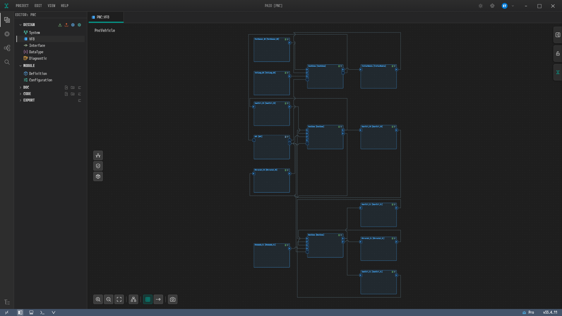
Figure 6-26. The VFB root of the finished example, which holds all 33 PortGroups (Auto Layout and Fit to View applied). The canvas looks the same as in Figure 6-16.
Turn the overlay on and click VFC_Comfort in the list, and the screen looks like Figure 6-27.
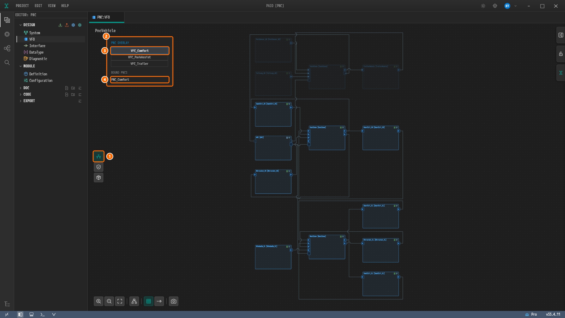
Figure 6-27. The finished example with the PNC Overlay on and VFC_Comfort selected. ① The VFC (PNC Overlay) icon. ② The PNC OVERLAY panel. ③ VFC_Comfort. ④ BOUND PNCS = PNC_Comfort. The four compositions at the top of the canvas are dimmed.

Figure 6-28. The PNC OVERLAY panel, zoomed in. The VFC list holds VFC_Comfort (selected), VFC_ParkAssist, and VFC_Trailer, and BOUND PNCS shows PNC_Comfort.
- Each VFC is listed as one button. Click a button to select that VFC.
- BOUND PNCS lists the PNCs that reference the selected VFC. The panel reads it from the PNC mappings in the SYSTEM and shows it here; you cannot edit it. If no PNC references the VFC, it shows
--.
Hold Ctrl and scroll the mouse wheel to zoom in on the canvas and read the names of the dimmed compositions.
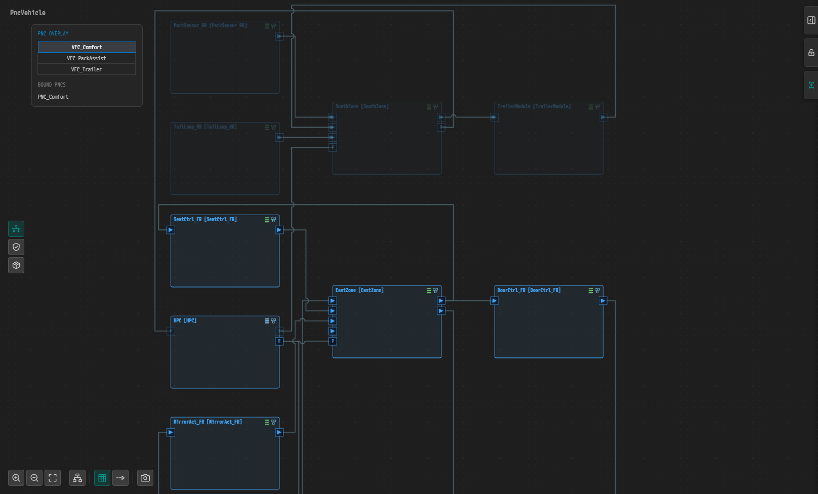
Figure 6-29. The VFC_Comfort overlay of the finished example, zoomed in. ParkSensor_RR, TailLamp_RR, SouthZone, and TrailerModule do not participate in VFC_Comfort and are dimmed, while the participating SeatCtrl_FR, EastZone, DoorCtrl_FR, HPC, and MirrorAct_FR appear normally.
Note. The PNC Overlay is for visualization only. You cannot change VFC membership or PNC bindings from the overlay. Edit the link between a VFC and a PNC in PNC Dialog — Per-PNC Binding.
Why Is It Designed This Way?
A PNC (Partial Network Cluster) references a VFC to state in the model which functions require that PNC to be awake. A VFC does not stay inside one ECU — it spans several ECUs and the HPC. That is why you have to chain PortGroups of the same name from the ports of an atomic SWC up through the ECU composition to the root composition: only then can you follow every participating port of a function from a single VFC at the root. Keeping the composition name identical to the node name serves the same purpose. You have to be able to find the node (machine) directly from a composition in order to know which ECUs and channels a VFC spans.
Check Your Work
- The VFB root
PncVehicleholds 14 compositions, each named after a node in the System editor. -
ParkSensor_RRcontains the atomic SWCParkDistanceSensing, and the twoParkDistanceports are joined by a delegation connector. - At the root,
ParkDistance(P) ofParkSensor_RRis joined toParkDistance(R) ofSouthZoneby an assembly connector. - After you close and reopen the editor, the header of the
ParkSensor_RRnode shows the ECU icon and readsParkSensor_RR [ParkSensor_RR]. - In the SWC Internal Behavior dialog of
ParkDistanceSensing, PORT GROUPS showsVFC_ParkAssist(PARTIAL_NETWORKING, OUTER PORTSParkDistance). - When you select the
ParkSensor_RRframe, PORT GROUPS on the COMPOSITION panel showsVFC_ParkAssistwith INNER GROUPSParkDistanceSensing/VFC_ParkAssist. - You have created every atomic SWC PortGroup listed in the tables under The Remaining PortGroups.
- When you click the VFC (PNC Overlay) icon at the root to turn the overlay on, the list holds three entries:
VFC_Comfort,VFC_ParkAssist, andVFC_Trailer. ChooseVFC_ParkAssist, and onlyHPC,SouthZone, andParkSensor_RRappear normally while the remaining compositions are dimmed. - BOUND PNCS still shows
--. You create the link between a VFC and a PNC in the next chapter. - The PNC:VFB tab has no unsaved-change marker.
Next Steps
In PNC Dialog — Per-PNC Binding you bind a VFC, an I-PDU Group, physical channels, service instances, and wakeup frames to each PNC.