Topology Design
What You Will Do
In this chapter you create a new project named PNC and draw the skeleton of the vehicle network — the topology — in the System editor.
You place the HPC, the zone ECUs, and the end ECUs, connect them through CAN FD clusters and an Ethernet cluster that carries two VLANs, embed an Ethernet switch inside the HPC, and then connect the switch ports to each Ethernet controller.
You build a few representative nodes directly on screen, and add the rest the same way while following the value tables.
When you finish this chapter, the System editor holds the zonal topology shown in Figure 2-1. The HPC sits at the top with BackboneSwitch beneath it, then three zone ECUs, and ten end ECUs along the bottom.
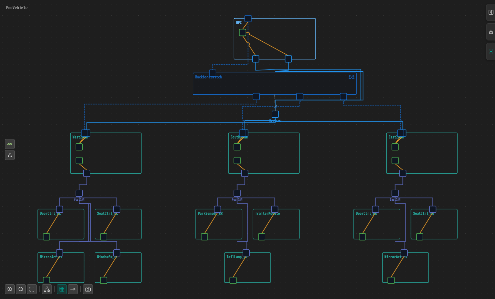
Figure 2-1. The topology you build in this chapter. HPC at the top, BackboneSwitch below it, WestZone, SouthZone, and EastZone in the middle row, and ten end ECUs at the bottom. PncVehicle in the upper-left corner of the canvas is the root name of the finished example project.
Before You Begin
- Review the three PNCs of this example and their participating ECUs in The Example and Its Design Goals.
- Start PAIO and begin from a window with no project open: the title bar reads
PAIO, the EDITOR view on the left showsNo project open, and the Welcome tab is open. If PAIO opens a project you worked on before, choose PROJECT › New Window to get such a window. - The full feature set of the System editor (formerly the IVC editor) is documented in IVC Editor. This chapter covers only the actions the tutorial needs.
You build the following elements yourself in this chapter. For the remaining elements, follow the tables in Adding the Remaining Nodes and Channels.
| Element | Name | Notes |
|---|---|---|
| HPC | HPC | Ethernet controller HPC_Eth, connector HPC_Eth_Body_Conn |
| Zone ECU | WestZone | CAN FD controller WestZone_CanFd, Ethernet controller WestZone_Eth |
| End ECU | DoorCtrl_FL | CAN FD controller DoorCtrl_FL_CanFd |
| CAN cluster | WestCAN | 500 kbps, channel WestCAN_Channel |
| Ethernet cluster | Backbone | Channels VLAN_Body (VLAN ID 100) and VLAN_Rear (VLAN ID 200) |
| Ethernet switch | BackboneSwitch | Embedded in the HPC, cluster Backbone |
| Coupling ports | HPC_Eth_Port, WestZone_Eth_Port, Port_0, Port_1 | Physical connection between a switch port and a controller port |
Creating the New Project
-
Click PROJECT in the menu at the top of the screen.
-
Click New Project... in the dropdown. It has no shortcut. The New Project button on the Welcome tab opens the same dialog.
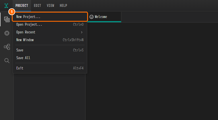
Figure 2-2. The PROJECT menu. ① The New Project... item.
-
In the New Project dialog, type
PNCinto Name. -
Set Location to the folder that will hold the project: type its path, or click Browse… and pick the folder. PAIO creates the project folder
PNCinside it, and the line below the fields shows that path asThe project will be created in …\PNC. Create stays disabled until both Name and Location are set. -
Click Create.
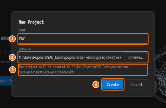
Figure 2-3. The New Project dialog. ① Name, ② Location and the Browse… button, ③ the line that names the new project folder, ④ the Create button. The folder in the figure is only an example; use a folder of your own.
-
Confirm that the same window has entered the new project: the title bar reads
PAIO [PNC], and the view on the left is headedEDITOR: PNC, with DESIGN and MODULE open. No editor tab is open yet. The project folderPNCholdsPNC.io.prjand the folderscode,design,doc,export,import, andworkflow.
Opening the System Editor
-
Look at the EDITOR view on the left. DESIGN lists System, VFB, Interface, DataType, and Diagnostic, and MODULE lists Definition and Configuration.
-
Click System under DESIGN. A single click opens the System editor.
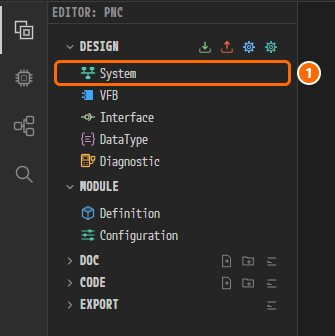
Figure 2-4. The EDITOR view of the PNC project. ① Click System under DESIGN.
-
The editor tab PNC:System opens with an empty canvas. The root name
Systemappears in the upper-left corner of the canvas.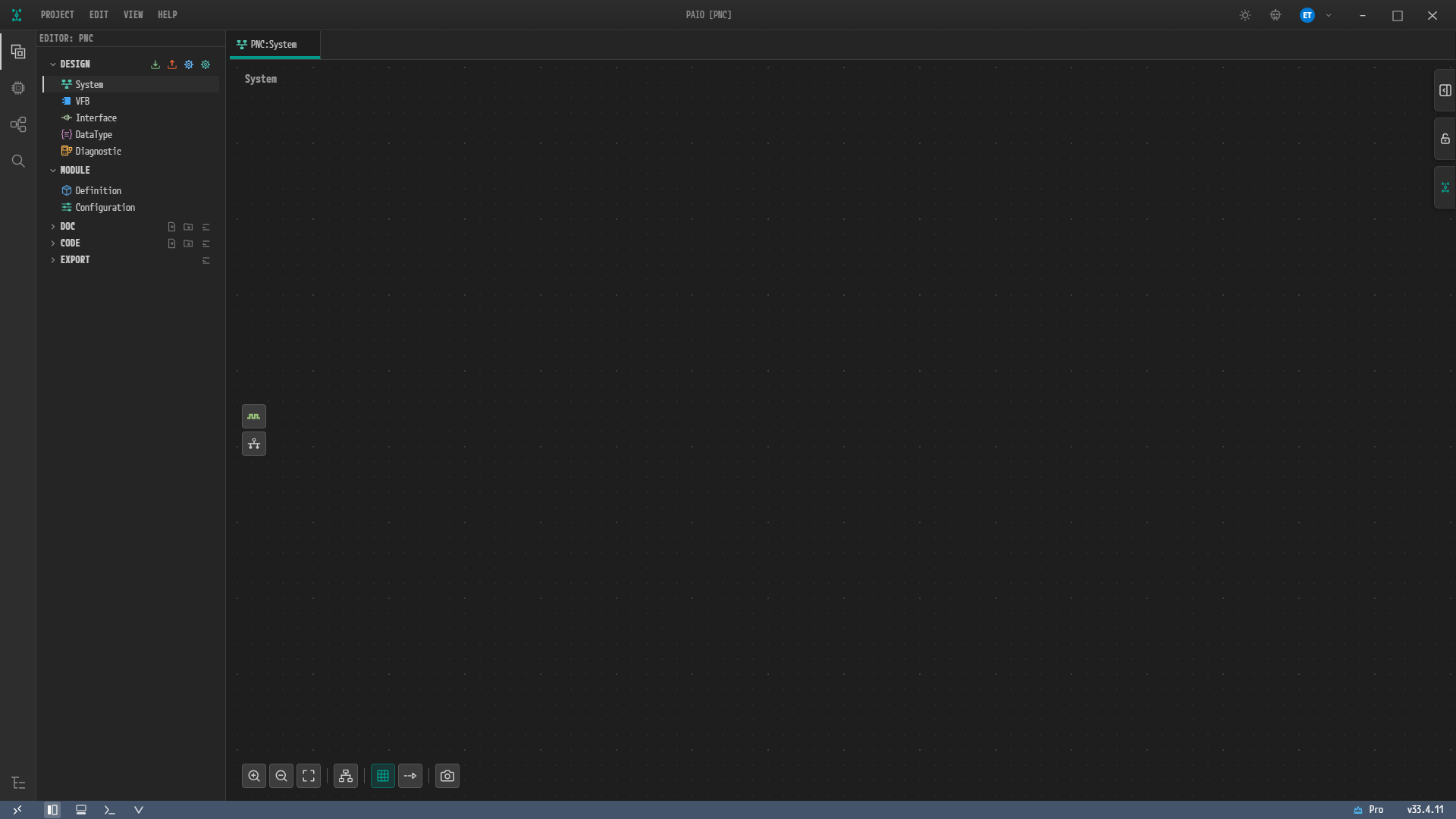
Figure 2-5. The System editor as first opened. The canvas is in the center, and the toolbar (zoom in, zoom out, Fit to View, Auto Layout, and so on) is at the lower left of the canvas. The two icons at the left edge of the canvas are Signal and Partial Network (PNC). The three buttons along the right edge show or hide the properties panel, lock it open, and (System, the PAIO logo) show the SYSTEM panel.
Note. The root name of a new project is
System. It is the name of the system, not of the editor. The finished screens in this chapter (Figure 2-1 and Figure 2-25) show the finished example project, so their root name readsPncVehicle. This does not affect following along.
Adding the HPC
-
Right-click an empty area of the canvas. The menu shows two items, Add ECU and Add HPC.
-
Click Add HPC. An
HPC_0node appears.
Figure 2-6. The canvas right-click menu. ① Add HPC.
-
Click the
HPC_0node. The properties panel titled HPC opens on the right. -
Type
HPCin NAME and pressTabto commit the value. The node name on the canvas changes toHPC.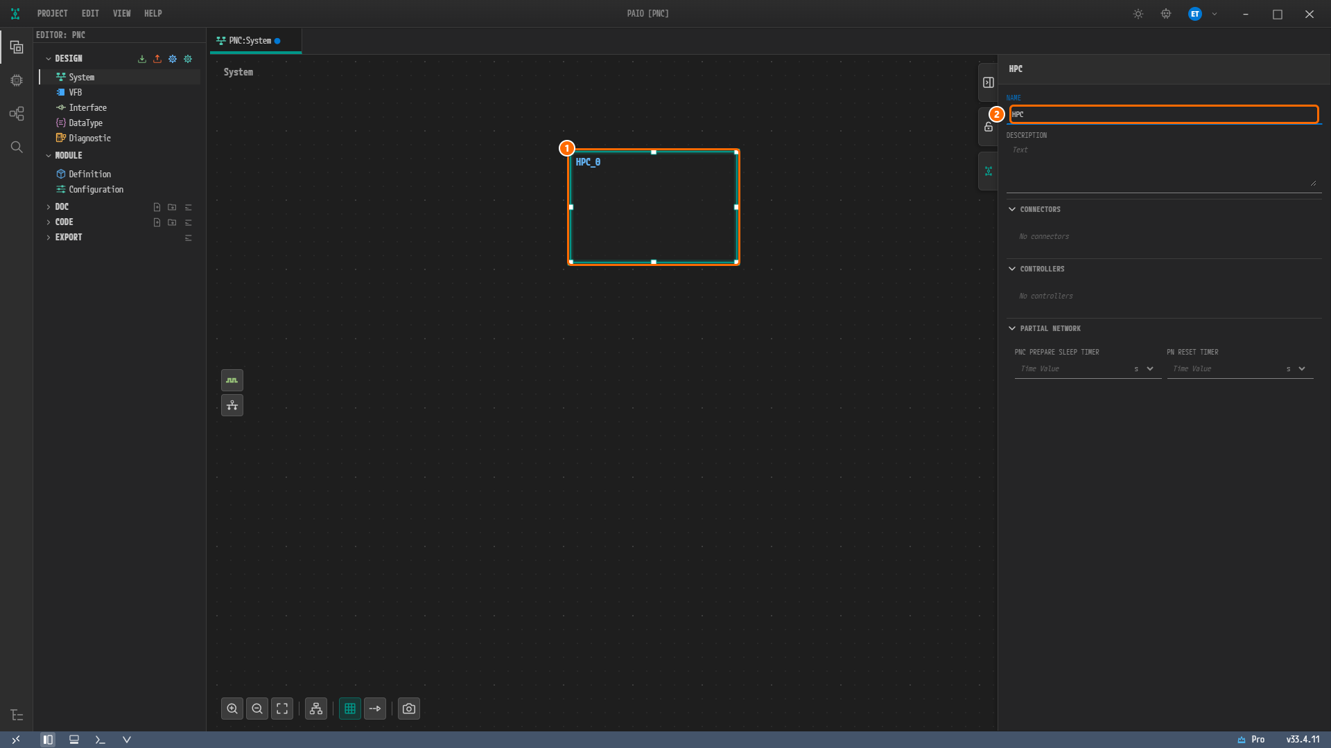
Figure 2-7. The HPC properties panel. ① The selected HPC node, ② the NAME field. While you edit, a dirty marker appears next to the tab name.
Adding the Zone ECU and the End ECU
-
Right-click an empty area of the canvas and click Add ECU. An
ECU_0node appears. -
Click the node and change NAME to
WestZone. -
Right-click an empty area of the canvas again and click Add ECU. Because you renamed the first ECU, the new node also gets the default name
ECU_0. -
Click the new node and change NAME to
DoorCtrl_FL.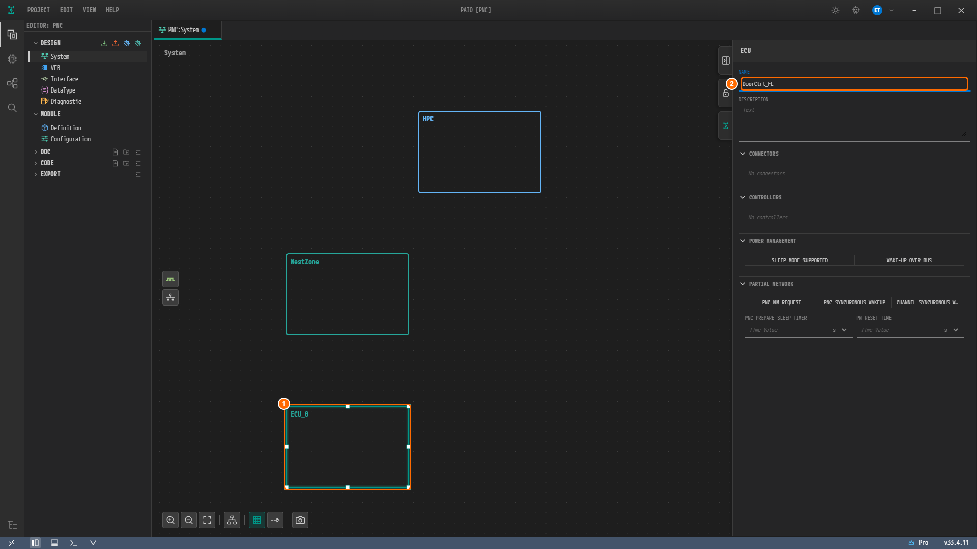
Figure 2-8. The ECU properties panel. ① The newly created ECU, ② the NAME field. The ECU panel has a POWER MANAGEMENT section, which the HPC panel does not have.
Adding the CAN FD Controller and Connector
A controller is the communication device inside an ECU, and a connector is the contact point where that controller meets the bus, that is, the channel. Start by creating them on WestZone.
-
Right-click an empty area inside the
WestZonenode. -
Select Add Controller ▸ CAN. A green rectangle — the controller — appears inside the node.
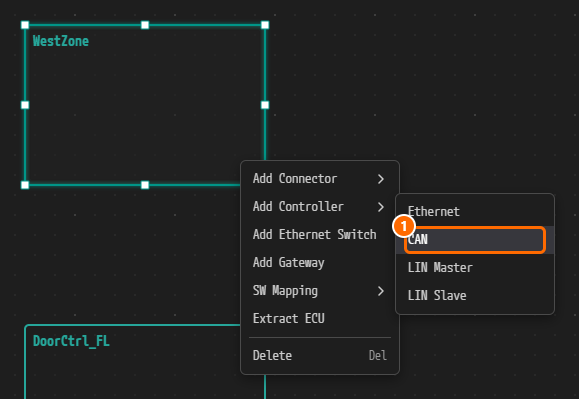
Figure 2-9. The WestZone right-click menu and its Add Controller submenu (Ethernet, CAN, LIN Master, LIN Slave). ① CAN.
Caution. If you right-click a connector on the node boundary or a controller inside the node, the menu for that element opens instead. The connector menu holds only Delete, plus Connect to Channel... once a cluster of the same kind exists. The area around the node name, that is, the header, easily overlaps a connector, so always right-click an empty area inside the node.
-
Click the green rectangle, the controller. The properties panel title changes to CAN CONTROLLER.
-
Change NAME to
WestZone_CanFd. -
In the CAN / CAN FD toggle at the right of the CAN CONTROLLER CONFIGURATION section header, click CAN FD. The fields below change to FD BIT TIMING CONFIGURATION and FD BIT TIMING REQUIREMENTS. This tutorial does not enter bit timing values.
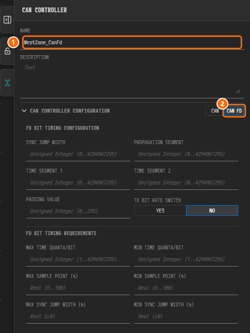
Figure 2-10. The CAN CONTROLLER panel. ① NAME, ② the CAN FD toggle.
-
Right-click an empty area inside
WestZoneand select Add Connector ▸ CAN. A connector, shown as a blue rectangle, appears on the node boundary. -
Click the connector. The properties panel title changes to CAN CONNECTOR. Until you select a controller in step 9, CONTROLLER reads
Select controller...in red withController is required, and the validation icon in the status bar shows a red badge1. -
Change NAME to
WestZone_CanFd_Conn. -
Select
WestZone_CanFdfrom the CONTROLLER list. An orange line appears on the canvas between the controller and the connector, and the red mark and the badge go away. CONNECTED CHANNEL is still (None).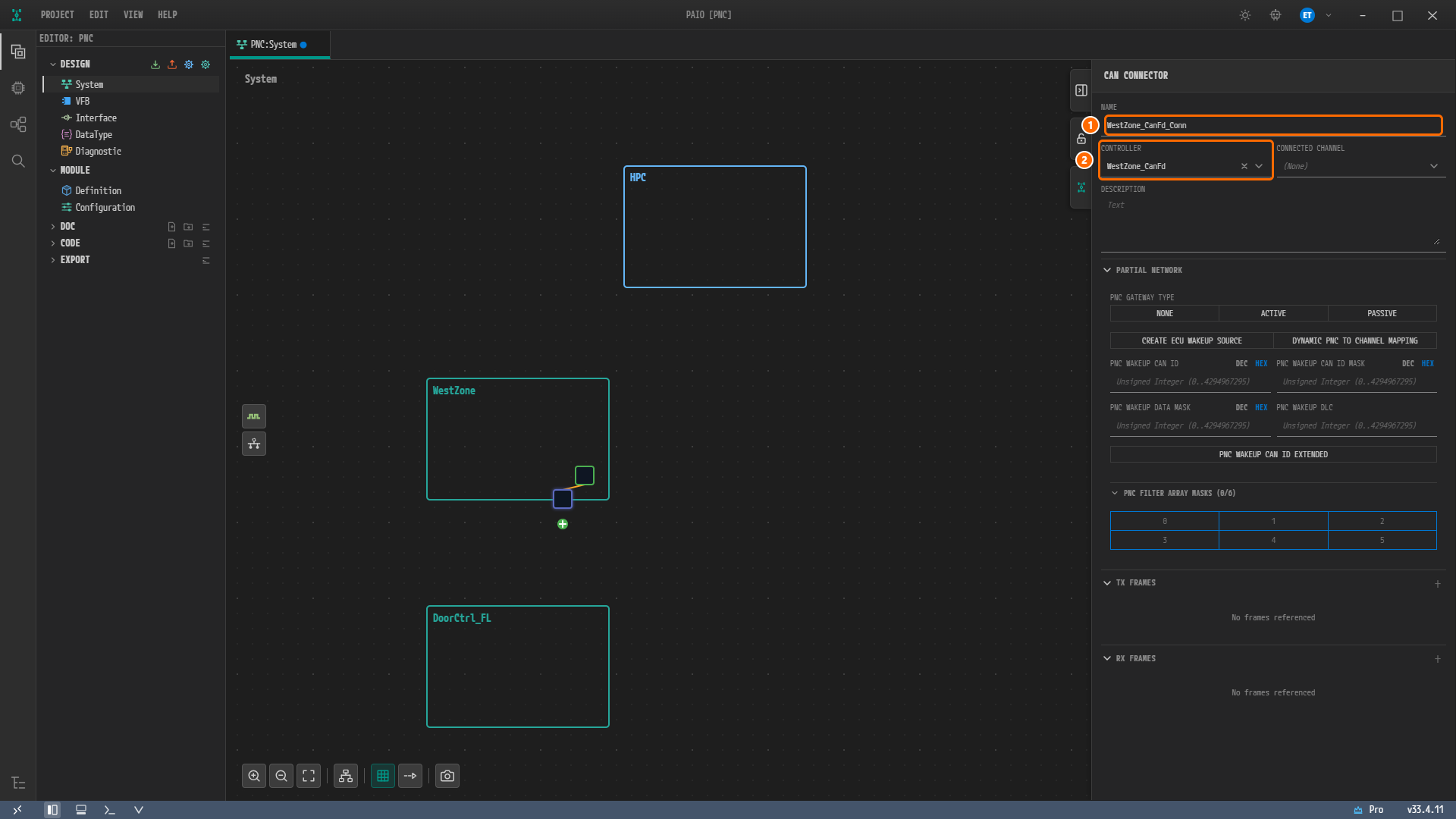
Figure 2-11. The CAN CONNECTOR panel. ① NAME, ② CONTROLLER. The green [+] badge below the connector on the canvas is used in the next section to create the cluster. You fill in the PARTIAL NETWORK section in Chapter 3.
-
Create a controller and a connector on
DoorCtrl_FLthe same way as in steps 1 through 9. The controller isDoorCtrl_FL_CanFd(CAN FD) and the connector isDoorCtrl_FL_CAN_Conn.
Note. The CAN connectors of zone ECUs end in
_CanFd_Conn, and those of end ECUs end in_CAN_Conn. This is the naming rule of the example files, so follow it as written.
Creating the CAN Cluster WestCAN
-
Click the green [+] badge below
WestZone_CanFd_Conn. No cluster exists yet, so the menu shows only Create CommunicationCluster [Can]. -
Click Create CommunicationCluster [Can]. A small purple rectangle — the CAN cluster, with the default name
CanCluster_0— appears and is connected to the connector.
Figure 2-12. The connector [+] badge menu. ① Create CommunicationCluster [Can].
-
Click the purple rectangle. The properties panel title changes to CAN CLUSTER.
-
Change NAME to
WestCAN. -
In the PROTOCOL section, click
500under BAUDRATE (ARBITRATION, KBPS). -
Change CHANNEL NAME in the PHYSICAL CHANNELS section to
WestCAN_Channel. Under Connected Connectors (1) you seeWestZone/WestZone_CanFd_Conn.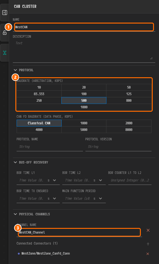
Figure 2-13. The CAN CLUSTER panel. ① NAME, ② BAUDRATE (ARBITRATION, KBPS) with 500 selected, ③ CHANNEL NAME. Below ② is CAN FD BAUDRATE (DATA PHASE, KBPS), left at Classical CAN.
-
Click the [+] badge below
DoorCtrl_FL_CAN_Conn. -
Select Connect to Channel... ▸ WestCAN ▸ WestCAN_Channel. The DoorCtrl_FL connector is now connected to WestCAN.
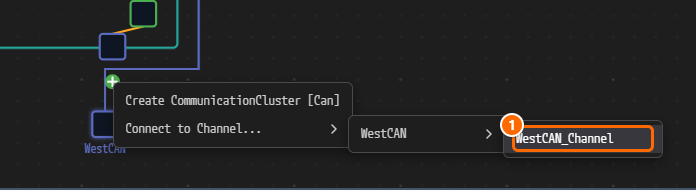
Figure 2-14. Once a cluster exists, the [+] menu also offers Connect to Channel.... ① WestCAN_Channel.
Note. In the example files the CAN clusters also carry a CAN FD setting, with a 2 Mbps data phase: their CAN FD BAUDRATE (DATA PHASE, KBPS) has
2000selected. Picking a rate there makes the cluster a CAN FD cluster. In this tutorial you leave it at Classical CAN and set CAN FD only through the CAN FD toggle of the controller.
Creating the Ethernet Cluster Backbone and Its VLAN Channels
-
Right-click an empty area inside
HPCand select Add Controller ▸ Ethernet. Click the new controller, the green rectangle, and change NAME toHPC_Eth. -
Right-click an empty area inside
HPCand select Add Connector ▸ Ethernet. Click the new connector, the rectangle on the node boundary, change NAME toHPC_Eth_Body_Conn, and set CONTROLLER toHPC_Eth. -
Click the [+] badge of
HPC_Eth_Body_Connand select Create CommunicationCluster [Ethernet]. An Ethernet cluster appears. -
Click the new cluster. The properties panel is titled ETHERNET CLUSTER. Change NAME to
Backbone. -
On the first channel under PHYSICAL CHANNELS, set CHANNEL NAME to
VLAN_Bodyand VLAN ID to100. -
Click + (Add Channel) at the right of the PHYSICAL CHANNELS header to add a second channel.
-
Set CHANNEL NAME of the second channel to
VLAN_Rearand VLAN ID to200. The VLAN ID field acceptsUNTAGGEDor a value from 1 to 4094.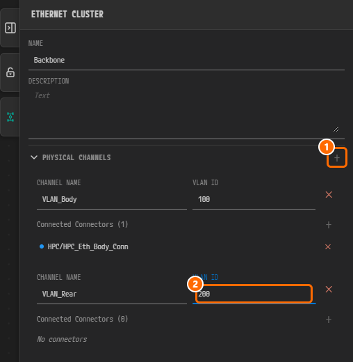
Figure 2-15. The ETHERNET CLUSTER panel. ① Add Channel (+), ② the VLAN ID of the second channel being typed. The first channel, VLAN_Body, already has HPC/HPC_Eth_Body_Conn connected to it.
-
Right-click an empty area inside
WestZoneand add Add Controller ▸ Ethernet (WestZone_Eth) and Add Connector ▸ Ethernet (WestZone_Eth_Conn, with CONTROLLER set toWestZone_Eth). -
Click the [+] badge of
WestZone_Eth_Connand select Connect to Channel... ▸ Backbone ▸ VLAN_Body (VLAN: 100) in that order.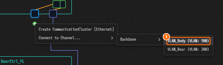
Figure 2-16. VLAN channels appear in the menu in the form "name (VLAN: number)". ① VLAN_Body (VLAN: 100).
Adding the Ethernet Switch
-
Right-click an empty area inside
HPCand click Add Ethernet Switch.EthSwitch_0appears inside the HPC.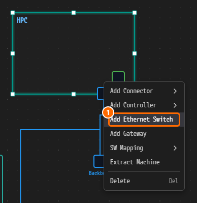
Figure 2-17. The HPC right-click menu. ① Add Ethernet Switch. The HPC menu offers Extract Machine instead of the Extract ECU of an ECU.
-
Click the switch node. The properties panel is titled COUPLING ELEMENT. Until you select a cluster in step 4, COMMUNICATION CLUSTER reads
-- Select --in red withCommunication Cluster is required. -
Change NAME to
BackboneSwitch. -
Select
Backbonefrom the COMMUNICATION CLUSTER list. Leave COUPLING TYPE at its default, SWITCH. COUPLING PORTS is still empty (No coupling ports).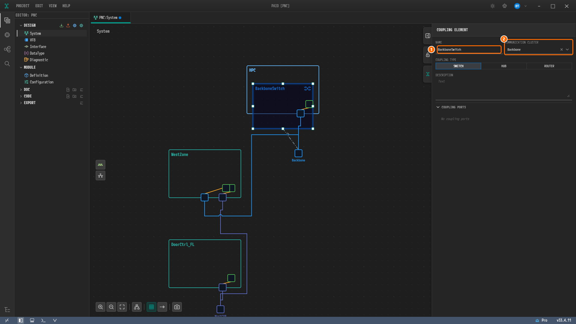
Figure 2-18. The COUPLING ELEMENT panel. ① NAME, ② COMMUNICATION CLUSTER. The dotted line from the switch to the Backbone cluster represents this cluster assignment.
Note. A freshly created embedded switch is drawn overlapping the HPC boundary, and the HPC node does not grow automatically. Running Auto Layout in the next section tidies it into the HPC. In the finished example (Figure 2-1) the switch is drawn separately just below the HPC because it has many ports, but it is still a switch embedded in the HPC.
Auto Layout and Saving
-
Click the Auto Layout button on the toolbar at the lower left of the canvas. A progress dialog appears briefly and disappears.
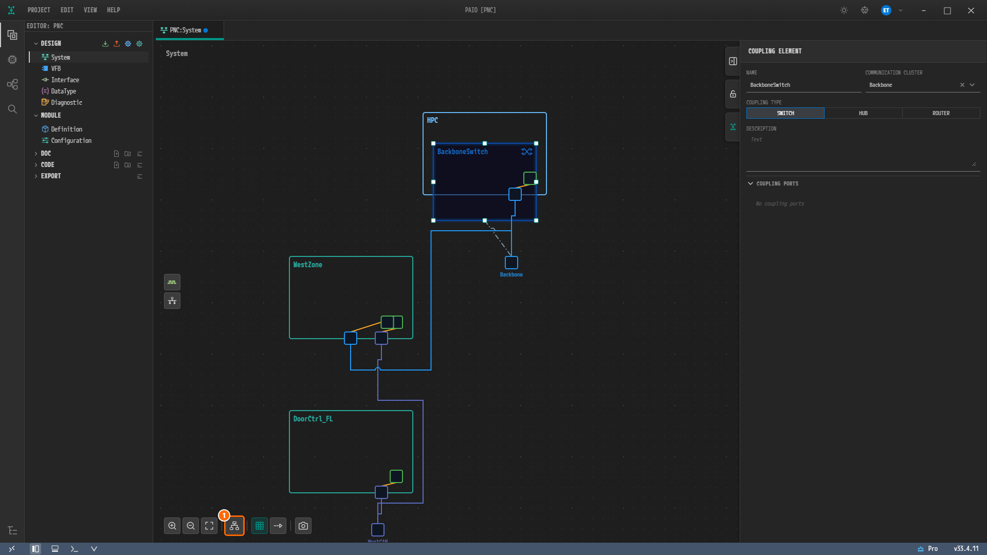
Figure 2-19. The canvas before Auto Layout. ① The Auto Layout button on the toolbar.
-
Press
Ctrl+Sto save. The dirty marker next to the tab name disappears.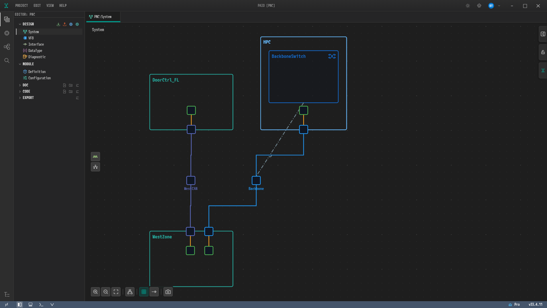
Figure 2-20. The canvas after Auto Layout and a save. The nodes are repositioned so that they no longer overlap, and BackboneSwitch now sits inside the HPC. The purple line is WestCAN, and the blue line is the VLAN_Body connection of Backbone.
Note. Auto Layout repositions nodes so that they do not overlap, but it does not arrange them into a top-to-bottom hierarchy. As in Figure 2-20, the end ECU
DoorCtrl_FLcan end up above the zone ECUWestZone. Drag the nodes if you want to move them.
Note. At this point the validation icon (V) in the status bar at the bottom of the screen carries no badge, as in Figures 2-19 and 2-20. A red number badge appears on it while the model has errors, such as a connector whose CONTROLLER is still empty. Validation results are covered in The System Editor and Validation.
Creating and Connecting the Switch Ports
A coupling port is the element that physically joins a switch and an ECU. Create a port on the Ethernet controller, create a port on the switch as well, and then join the two ports through the Connect to Port... menu.
Caution. The Connect to Port... candidate list shows only ports that belong to the same Ethernet cluster and are not yet connected. The cluster of a controller port is determined by the channel that the connector referencing that controller is connected to, so you must connect the connector to a channel, as in the previous section, before you create the port. If you right-click a port that is already connected, the menu shows only Delete and no Connect to Port....
-
Right-click the
HPC_Ethcontroller — the green rectangle — insideHPCand click Add Coupling Port. The controller right-click menu holds only this item and Delete.
Figure 2-21. The Ethernet controller right-click menu. ① Add Coupling Port.
-
Click the port that appears on the node boundary and change NAME to
HPC_Eth_Port. The default name is<controller name>_Port_<number>. -
Create a port on the
WestZone_Ethcontroller ofWestZonethe same way and change NAME toWestZone_Eth_Port.
Note. An Ethernet controller can have only one coupling port. If a port already exists, the Add Coupling Port item is disabled.
-
Right-click the
BackboneSwitchnode insideHPCand click Add CouplingPort. Unlike the controller side, the label on the switch side is Add CouplingPort, written without a space.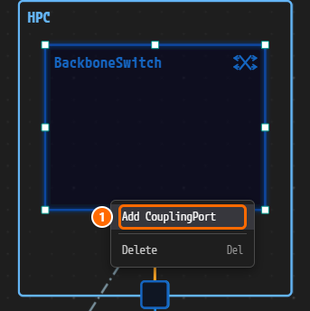
Figure 2-22. The right-click menu of BackboneSwitch inside the HPC. ① Add CouplingPort.
-
Click the port that just appeared. The properties panel title changes to COUPLING PORT.
-
Change NAME to
Port_0, and in the PORT SETTINGS section set PORT ROLE to HOST-PORT, PHYSICAL LAYER TYPE to 1000BASE-T1, and NEGOTIATION to AUTO. A switch port without NEGOTIATION is reported as aconstr_5251error in validation.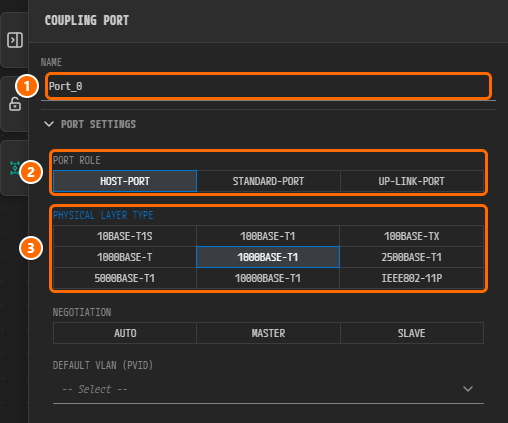
Figure 2-23. The COUPLING PORT panel. ① NAME, ② PORT ROLE (choose among HOST-PORT, STANDARD-PORT, and UP-LINK-PORT), ③ PHYSICAL LAYER TYPE (1000BASE-T1 selected). NEGOTIATION (AUTO, MASTER, SLAVE) below ③ is not set yet.
Note. The DEFAULT VLAN (PVID) list appears only on ports owned by a switch. A port owned by a controller is an end point of the communication, so the PVID and VLAN membership items are not shown. You set VLAN membership in the switch workbench, not in this panel.
- Right-click a different spot on
BackboneSwitchand create one more port with Add CouplingPort. Change NAME toPort_1. A new port has no PORT ROLE selected, so click STANDARD-PORT. Set PHYSICAL LAYER TYPE to 1000BASE-T1 and NEGOTIATION to AUTO.
Caution. A new port attaches to the node boundary closest to the spot you right-clicked. If you right-click the same spot twice, the two ports overlap completely and you can no longer click the port you created first. Create the second port by right-clicking a different position on the boundary.
-
Right-click
Port_0and select Connect to Port... ▸ HPC_Eth / HPC_Eth_Port. -
Right-click
Port_1and select Connect to Port... ▸ WestZone_Eth / WestZone_Eth_Port. A blue dotted line is drawn between the connected ports.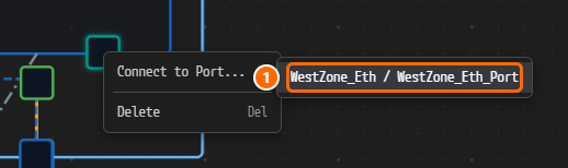
Figure 2-24. The Connect to Port... submenu of the switch port right-click menu. ① WestZone_Eth / WestZone_Eth_Port. Candidates appear in the form "name of the element that owns the port / port name" rather than as node names.
-
Press
Ctrl+Sto save.
Adding the Remaining Nodes and Channels
Repeat exactly the steps you used above to add the remaining elements. Use the names and values in the tables below as written.
- Nodes: right-click an empty area of the canvas → Add ECU → click the node → type the NAME
- Controllers and connectors: right-click an empty area inside the node → Add Controller ▸ CAN / Ethernet, Add Connector ▸ CAN / Ethernet → click each one, type the NAME, and set the CONTROLLER of the connector. Turn on CAN FD for every CAN controller. For
HPC_Eth_Rear_Conn, add one more connector insideHPCand set its CONTROLLER to the sameHPC_Eth. - Clusters: [+] on the first connector you attach to that cluster → Create CommunicationCluster [Can] → type the cluster NAME, click
500under BAUDRATE (ARBITRATION, KBPS), and type CHANNEL NAME - Channel connections: [+] on the connector → Connect to Channel... ▸ cluster ▸ channel
Node Table
| Node | Kind | Controllers | Connectors | Channel to connect |
|---|---|---|---|---|
HPC | HPC | HPC_Eth (Ethernet) | HPC_Eth_Body_Conn, HPC_Eth_Rear_Conn | VLAN_Body, VLAN_Rear |
WestZone | ECU (zone) | WestZone_Eth (Ethernet), WestZone_CanFd (CAN FD) | WestZone_Eth_Conn, WestZone_CanFd_Conn | VLAN_Body, WestCAN_Channel |
SouthZone | ECU (zone) | SouthZone_Eth (Ethernet), SouthZone_CanFd (CAN FD) | SouthZone_Eth_Conn, SouthZone_CanFd_Conn | VLAN_Rear, RearCAN_Channel |
EastZone | ECU (zone) | EastZone_Eth (Ethernet), EastZone_CanFd (CAN FD) | EastZone_Eth_Conn, EastZone_CanFd_Conn | VLAN_Body, EastCAN_Channel |
DoorCtrl_FL | ECU | DoorCtrl_FL_CanFd (CAN FD) | DoorCtrl_FL_CAN_Conn | WestCAN_Channel |
SeatCtrl_FL | ECU | SeatCtrl_FL_CanFd (CAN FD) | SeatCtrl_FL_CAN_Conn | WestCAN_Channel |
MirrorAct_FL | ECU | MirrorAct_FL_CanFd (CAN FD) | MirrorAct_FL_CAN_Conn | WestCAN_Channel |
WindowSw_FL | ECU | WindowSw_FL_CanFd (CAN FD) | WindowSw_FL_CAN_Conn | WestCAN_Channel |
ParkSensor_RR | ECU | ParkSensor_RR_CanFd (CAN FD) | ParkSensor_RR_CAN_Conn | RearCAN_Channel |
TrailerModule | ECU | TrailerModule_CanFd (CAN FD) | TrailerModule_CAN_Conn | RearCAN_Channel |
TailLamp_RR | ECU | TailLamp_RR_CanFd (CAN FD) | TailLamp_RR_CAN_Conn | RearCAN_Channel |
DoorCtrl_FR | ECU | DoorCtrl_FR_CanFd (CAN FD) | DoorCtrl_FR_CAN_Conn | EastCAN_Channel |
SeatCtrl_FR | ECU | SeatCtrl_FR_CanFd (CAN FD) | SeatCtrl_FR_CAN_Conn | EastCAN_Channel |
MirrorAct_FR | ECU | MirrorAct_FR_CanFd (CAN FD) | MirrorAct_FR_CAN_Conn | EastCAN_Channel |
Cluster Table
| Cluster | Kind | BAUDRATE (ARBITRATION, KBPS) | Channel (VLAN ID) | Connected connectors |
|---|---|---|---|---|
Backbone | Ethernet | — | VLAN_Body (100) | HPC_Eth_Body_Conn, WestZone_Eth_Conn, EastZone_Eth_Conn |
VLAN_Rear (200) | HPC_Eth_Rear_Conn, SouthZone_Eth_Conn | |||
WestCAN | CAN | 500 | WestCAN_Channel | WestZone_CanFd_Conn, DoorCtrl_FL_CAN_Conn, SeatCtrl_FL_CAN_Conn, MirrorAct_FL_CAN_Conn, WindowSw_FL_CAN_Conn |
RearCAN | CAN | 500 | RearCAN_Channel | SouthZone_CanFd_Conn, ParkSensor_RR_CAN_Conn, TrailerModule_CAN_Conn, TailLamp_RR_CAN_Conn |
EastCAN | CAN | 500 | EastCAN_Channel | EastZone_CanFd_Conn, DoorCtrl_FR_CAN_Conn, SeatCtrl_FR_CAN_Conn, MirrorAct_FR_CAN_Conn |
Switch Port Table
The BackboneSwitch of the finished example has four ports, and each port is physically connected to the Ethernet controller port (<node>_Eth_Port) of the HPC or of a zone ECU. PHYSICAL LAYER TYPE is 1000BASE-T1 and NEGOTIATION is AUTO on every port.
| Port | Role | Connected to | VLAN |
|---|---|---|---|
Port_0 | HOST | HPC/HPC_Eth_Port | VLAN_Body, VLAN_Rear |
Port_1 | STD | WestZone/WestZone_Eth_Port | VLAN_Body |
Port_2 | STD | SouthZone/SouthZone_Eth_Port | VLAN_Rear |
Port_3 | STD | EastZone/EastZone_Eth_Port | VLAN_Body |
PNC Definitions and Connector PNC Properties attaches PNCs to the switch ports, so create the ports as listed in the table. The procedure follows. For details, see sections 6.4.3, 6.4.4, and 6.5.4 of IVC Editor.
- Create ports on the
SouthZone_EthandEastZone_Ethcontrollers the same way as in Creating and Connecting the Switch Ports, and change NAME toSouthZone_Eth_PortandEastZone_Eth_Port. - Create two more ports on
BackboneSwitchand change NAME toPort_2andPort_3. Right-click a different spot on the boundary for each port. For PORT ROLE, onlyPort_0is HOST-PORT; set the rest to STANDARD-PORT. Set PHYSICAL LAYER TYPE to 1000BASE-T1 and NEGOTIATION to AUTO on both. - Right-click a switch port and choose the target port from the table in the Connect to Port... submenu. Candidates appear in the form "controller name / port name", such as
SouthZone_Eth / SouthZone_Eth_Port. - Double-click
BackboneSwitchto open the workbench, and for each port set DEFAULT VLAN (PVID) and VLAN MEMBERSHIP to the VLAN listed in the table. For the default VLAN, onlyPort_2usesVLAN_Rear; the rest useVLAN_Body.
Once you have added every element, run Auto Layout and save with Ctrl+S.
Reviewing the Finished Example
The finished topology looks like Figure 2-25. The figure shows the finished example project, so the node layout and the root name (PncVehicle) may differ from the project you built. What matters is that the nodes, clusters, and connections match.
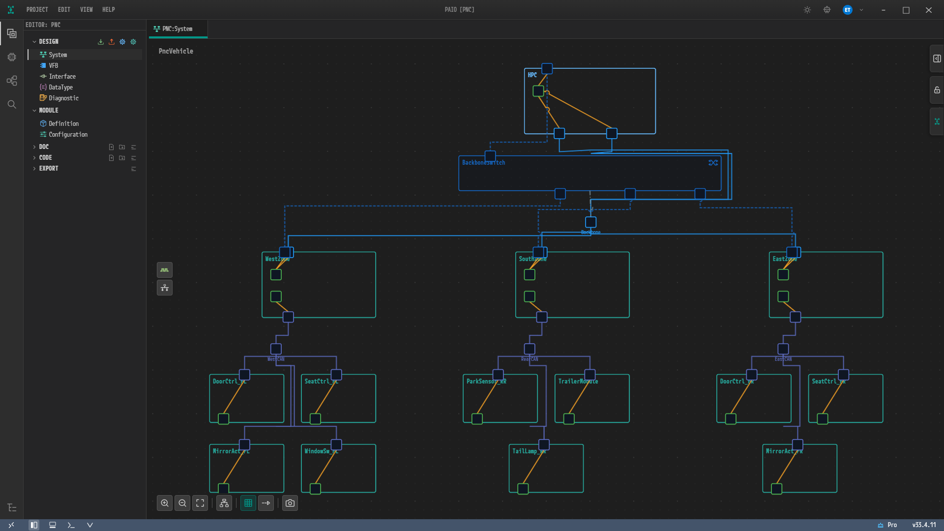
Figure 2-25. The System editor with the finished example open (whole view through Fit to View on the toolbar, properties panel collapsed). The small blue rectangle in the center is the Backbone cluster, and the purple rectangles under each zone are the WestCAN, RearCAN, and EastCAN clusters, each with its name below it. Solid lines are the connections between connectors and channels, and blue dotted lines are the physical connections between switch ports and Ethernet controller ports.
Cluster nodes are drawn as small rectangles with their names below them. Hovering the mouse over a rectangle also shows its kind and, for a CAN cluster, its baud rate. Hold Ctrl and turn the mouse wheel to zoom in around the pointer position.
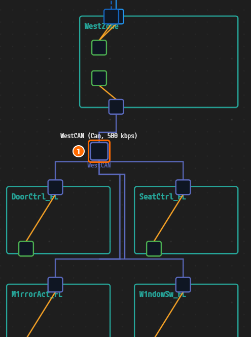
Figure 2-26. Hovering the mouse over the purple rectangle below WestZone (①) shows the cluster name, kind, and baud rate above it, such as "WestCAN (Can, 500 kbps)". The name WestCAN is also written below the rectangle. The DoorCtrl_FL, SeatCtrl_FL, MirrorAct_FL, and WindowSw_FL nodes below it are connected to this cluster.
Note. In the finished example the connector icons hide part of the node names, so names such as
WestZoneandDoorCtrl_FLlook truncated. Click a node and read its name in NAME on the properties panel.
Double-click the BackboneSwitch node to open the Ethernet Switch Configuration [BackboneSwitch] workbench. If you created every port, the center shows the four ports with the target each one connects to, and the SWITCH panel on the right shows the switch settings and a PORTS (4) summary table. Close it with Close once you have checked it.
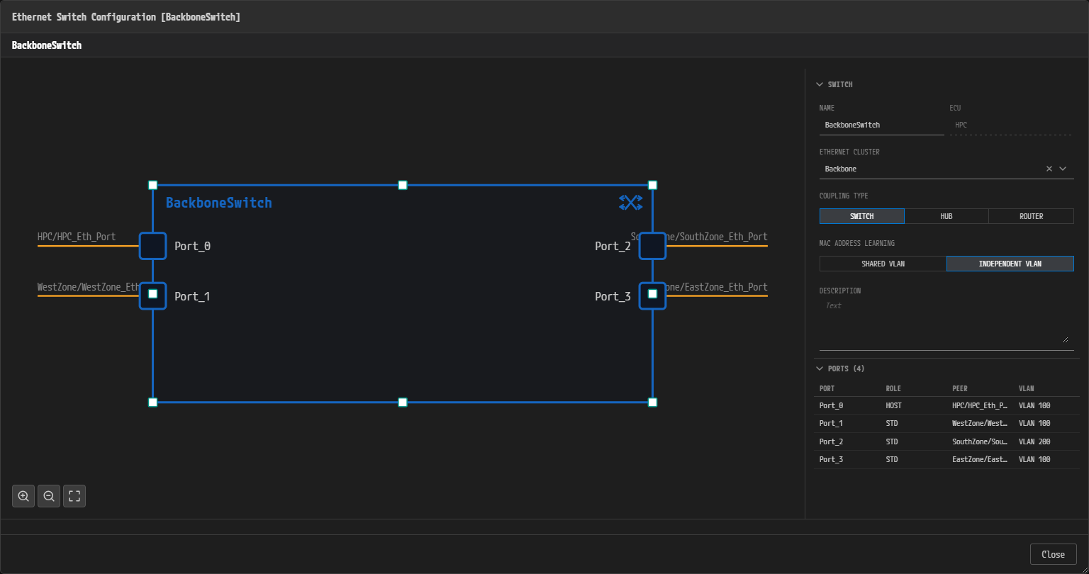
Figure 2-27. The BackboneSwitch workbench. The SWITCH panel shows NAME BackboneSwitch, ECU HPC, ETHERNET CLUSTER Backbone, COUPLING TYPE SWITCH, and MAC ADDRESS LEARNING INDEPENDENT VLAN. In the PORTS (4) table, only Port_0 has the HOST role and only Port_2 uses VLAN 200. The connection target labels and the PEER column of the ports on the right look truncated because of their length.
Why Split the Backbone into Two VLANs?
Design rationale. The PNC (Partial Network Cluster) coordination rules of AUTOSAR require two things together.
constr_5093: a physical channel may have at most one connector whose PNC gateway type is active.constr_3781: every PNC must have a top-level PNC coordinator. That is, it needs an ECU that is connected to two or more of the relevant channels and whose connections are all active.The HPC is an AP machine, so it cannot be a PNC gateway. If the backbone were a single channel, only one of the three zones could be active, and the PNCs of the remaining zones would lose their coordinator. Splitting the backbone into a Body domain (
VLAN_Body: West and East) and a Rear domain (VLAN_Rear: South) lets each VLAN have one active gateway. WestZone becomes the top-level coordinator of PNC_Comfort, and SouthZone becomes the top-level coordinator of PNC_ParkAssist and PNC_Trailer. EastZone becomes a subordinate coordinator whose gateway on the VLAN_Body side is passive. You enter the gateway settings in PNC Definitions and Connector PNC Properties.
Check Your Work
- The title bar reads
PAIO [PNC], and clicking System under DESIGN in the EDITOR view opens the editor tab PNC:System. - The canvas holds
HPC, three zone ECUs (WestZone,SouthZone,EastZone), and ten end ECUs. - CAN FD is selected under CAN CONTROLLER CONFIGURATION on every CAN controller.
- BAUDRATE (ARBITRATION, KBPS) of the
WestCAN,RearCAN, andEastCANclusters has500selected, and the Connected Connectors of each channel match the cluster table. - The
Backbonecluster has the channelsVLAN_Body(VLAN ID 100) andVLAN_Rear(VLAN ID 200). - The Ethernet controller of the HPC and of each of the three zone ECUs has a coupling port
<node>_Eth_Port, and each one is connected toPort_0throughPort_3ofBackboneSwitchwith a blue dotted line drawn. - NEGOTIATION is AUTO on every port of
BackboneSwitch. - In the SWITCH panel of the
BackboneSwitchworkbench, ECU isHPCand ETHERNET CLUSTER isBackbone. - The PORTS (4) table of the
BackboneSwitchworkbench matches the switch port table (onlyPort_0is HOST, and onlyPort_2uses VLAN 200). - You saved with
Ctrl+S, so there is no dirty marker next to the tab name.
Next Steps
In PNC Definitions and Connector PNC Properties you define the three PNCs and enter PNC properties such as gateway, wakeup, and filter mask on the connectors you created in this chapter.