Signals, PDUs, Frames and I-PDU Groups
What You Will Do
What a PNC (Partial Network Cluster) actually starts and stops is the I-PDU group — a group that bundles I-Signal I-PDUs. In this chapter you create CAN frames, I-Signal I-PDUs, signals and NM (Network Management)-PDUs yourself in the Signal editor and map them to each other. You then create the per-PNC I-PDU groups in the PNC dialog and put PDUs into them.
When you finish this chapter, you reach the following state.
- The Signal model holds 42 signals, 16 I-Signal I-PDUs, 18 NM-PDUs and 29 CAN frames (16 application frames plus 13 NM frames). The Signal editor in the current version cannot create the 13 NM frames, so a project you built yourself from Chapter 2 onward stops at the 16 application frames (see Creating NM-PDUs).
- You can find frames, PDUs, signals, NM frames and NM-PDUs in the Signal editor and check their values.
- PNC GROUPS in the PNC dialog holds 4 groups for
PNC_Comfort, 2 groups forPNC_ParkAssistand 2 groups forPNC_Trailer, and each group contains PDUs.
Before You Begin
- Finish PNC Definitions and Connector PNC Properties so that the three PNCs (17, 18, 19) are defined.
- In this chapter you build one representative set from scratch: the CAN frame
WestCAN_DoorStatus_FL, the I-Signal I-PDUDoorStatus_FL_Pduthat is created together with it, the signalsDoorOpen_FL,DoorLock_FLandWindowPos_FL, the NM-PDUWestCAN_NmPdu_WestZone, and the I-PDU groupWestCAN_PNC_Comfort_Rx. For the rest you repeat the same operations from the value tables. - The procedure figures show a project in which the remaining frames and PDUs are already in place and only the representative set is created anew. The item counts below the lists therefore start at CAN FRAMES "27 items" and PDUS "32 items". The "33 items" visible in the PDU tab figure is the count after the representative frame added one PDU (Figure 4-6). The figures from Looking at a CAN Frame onward show the example built to the end (29 frames, 34 PDUs, 42 signals). Only the item counts differ; the labels, the button positions and the values you type are the same.
- The Signal editor in the current version cannot create the 13 NM frames. The reason and the workaround are described in Creating NM-PDUs.
- For the full feature set of the Signal editor, see Signal editor.
Opening the Signal Editor
-
In the EDITOR view on the left, click System under DESIGN to open the System editor (tab PNC:System). Then, in the vertical icon strip along the left edge of the canvas, click the first (upper) icon, Signal. DESIGN has no Signal row, so the Signal editor is opened from this icon.
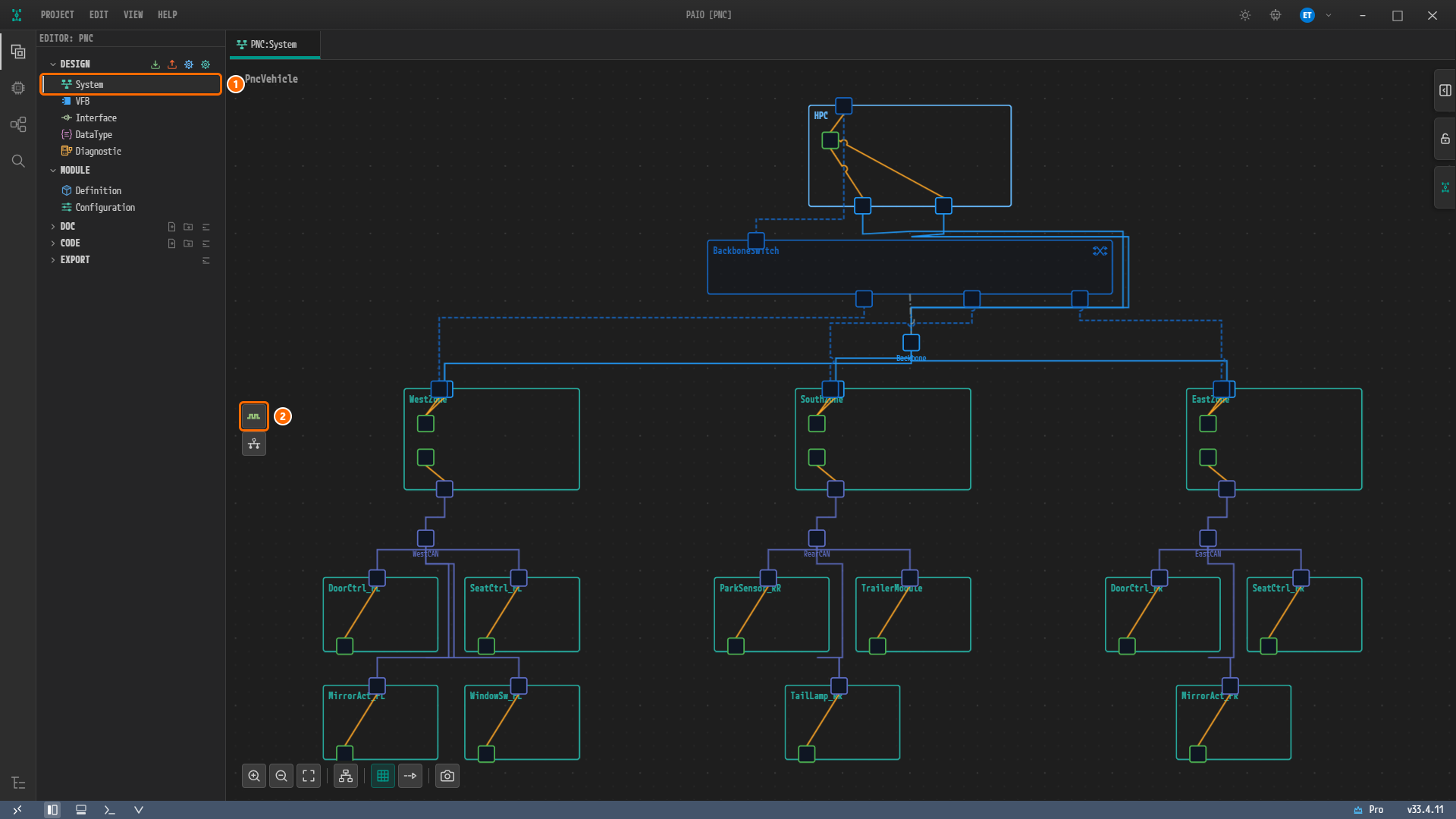
Figure 4-1. The System editor. ① System under DESIGN in the EDITOR view, ② Signal, the first (upper) icon in the vertical icon strip along the left edge of the canvas. The icon below it is Partial Network (PNC).
-
An editor tab titled PNC:Signal opens. Across the top of the editor are the protocol tabs CAN, LIN, PDU and SIGNAL, with CAN selected initially.
The editor is divided into three parts.
| Area | Contents |
|---|---|
| Left list | The elements of the selected tab (CAN FRAMES, PDUS, SIGNALS). The item count appears below the list. |
| Center | CONFIGURATION (the properties of the selected element) and the SIGNALS table below it |
| Right | Two tabs to the right of the CONFIGURATION fields: PREVIEW (the byte and bit layout grid) and PDU REFERENCES (the PDUs a frame carries). A PDU has PREVIEW only. PREVIEW is selected when the editor opens, and the tab you pick stays selected when you select another frame. On the SIGNAL tab this area is the SIGNAL GROUPS panel. |
Creating a CAN Frame and Its PDU
Build the one representative frame WestCAN_DoorStatus_FL all the way through. For the rest, repeat the same method from the Remaining Frames, PDUs and Signals table.
-
Confirm that the CAN tab is selected.
-
Click + (tooltip Add) to the right of the CAN FRAMES header. The − next to it deletes, and ⋯ holds sorting and filtering.
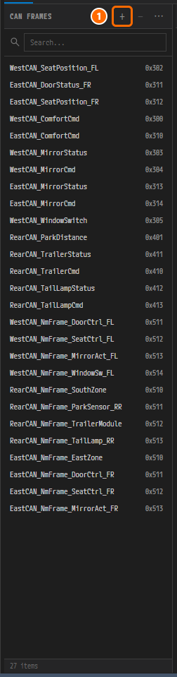
Figure 4-2. The CAN FRAMES list. ① + (tooltip Add) to the right of the header. "27 items" appears below the list.
-
NewFrameappears at the bottom of the list and is selected automatically. If that name is already taken, a number is appended. At the same time the I-Signal I-PDUNewFrame_Pduis created and linked to the frame. Click the PDU REFERENCES tab in the right column to see it. Because creating a frame brings a PDU with it, you do not need to create the PDU separately.Field Default value of a new frame NAME NewFrameADDRESSING STANDARD CAN ID The first value counting up from 0x100that is not yet in useDLC 8 (8 bytes)UNUSED BIT PATTERN 0PDU REFERENCES NewFrame_Pdu(LENGTH8, SIGNALS0)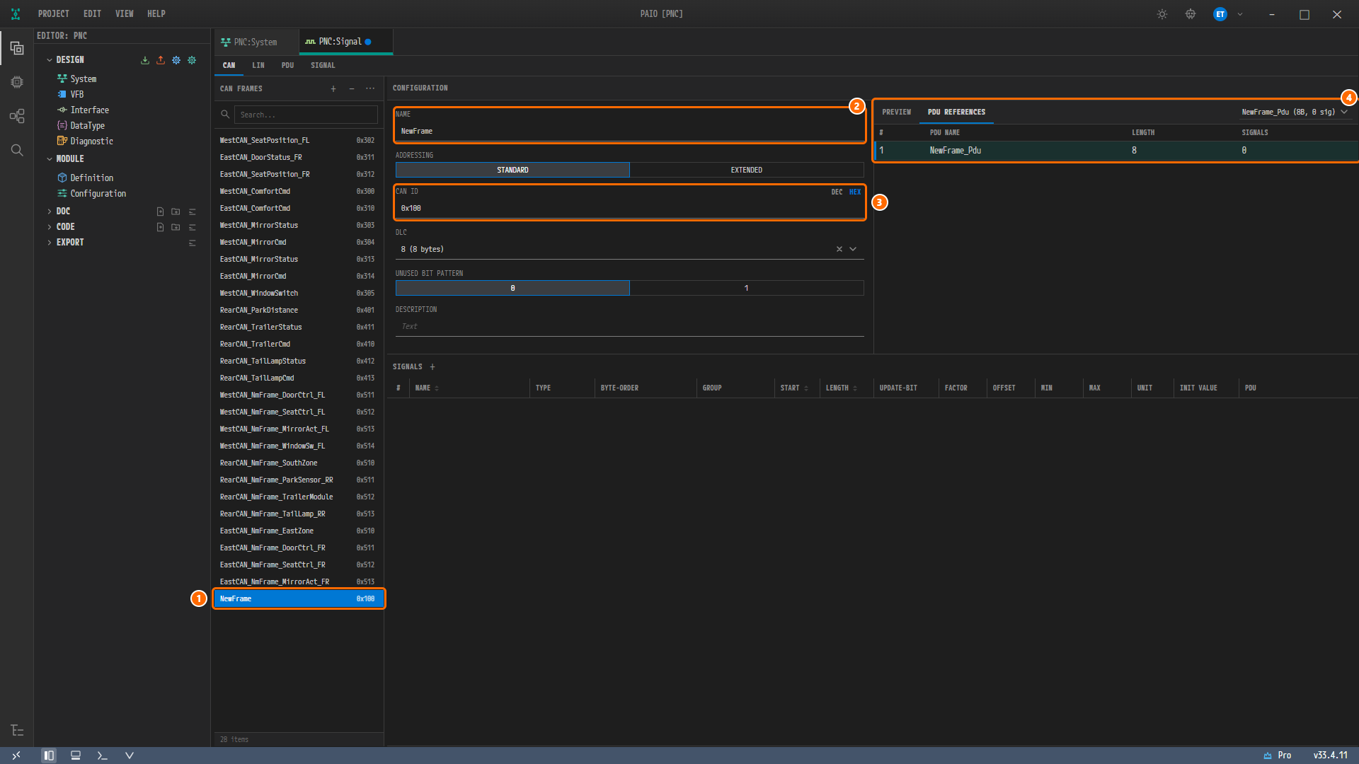
Figure 4-3. Right after clicking + and then the PDU REFERENCES tab. ①
NewFrame(0x100) added at the bottom of the list, ② NAME =NewFrame, ③ CAN ID =0x100, ④NewFrame_Pduon the PDU REFERENCES tab (LENGTH8, SIGNALS0). The item count below the list rises to "28 items", and a dirty marker appears next to the tab name PNC:Signal. -
Click the NAME field in CONFIGURATION, type
WestCAN_DoorStatus_FLand pressEnter. -
Click the CAN ID field, type
0x301and pressEnter. -
Leave ADDRESSING at STANDARD, DLC at
8 (8 bytes)and UNUSED BIT PATTERN at0. ADDRESSING and UNUSED BIT PATTERN are not input fields but buttons that place two values side by side.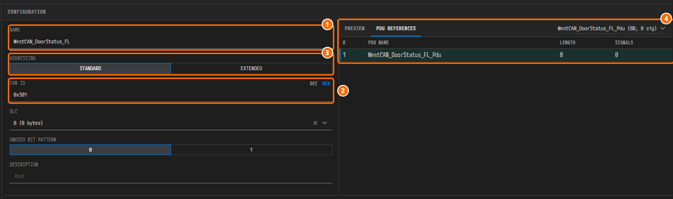
Figure 4-4. Close-up of CONFIGURATION. ① NAME =
WestCAN_DoorStatus_FL, ② CAN ID =0x301, ③ ADDRESSING = STANDARD (the STANDARD | EXTENDED button), ④ the PDU REFERENCES tab. The PDU has already followed the frame name, so the combo box at the right end of the tab bar and the table readWestCAN_DoorStatus_FL_Pdu.The DEC | HEX control to the right of the CAN ID label switches the notation, and the default is HEX.

Figure 4-5. Switching the CAN ID notation. ① The DEC | HEX button, ② the value
769with DEC selected. The stored value is the same. -
Click the PDU tab. The list title changes to PDUS. The PDU created alongside the frame has followed the frame name and now reads
WestCAN_DoorStatus_FL_Pdu. Click that item (the IS tag).Field Default value of a new PDU LENGTH (BYTES) 8UNUSED BIT PATTERN 0CYCLE TIME (MS) 0TRANSMISSION MODE NONE 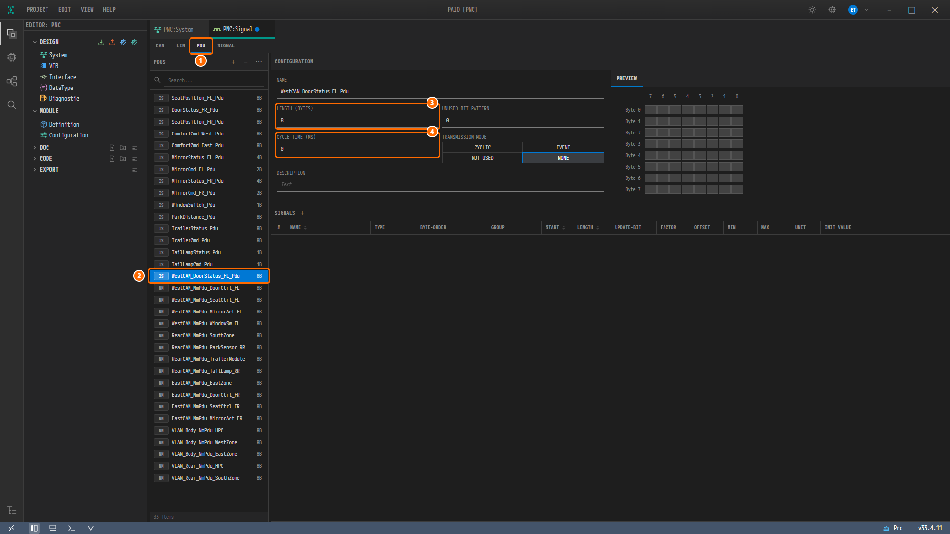
Figure 4-6. The PDU tab. ① The PDU tab, ②
WestCAN_DoorStatus_FL_Pduin the list (IS tag,8B), ③ LENGTH (BYTES) =8, ④ CYCLE TIME (MS) =0. TRANSMISSION MODE is set to NONE. -
Type
DoorStatus_FL_Pduin the NAME field. When you rename a PDU, the references from the frames and I-PDU groups that point to it are renamed as well. -
Leave LENGTH (BYTES) at
8and type50in CYCLE TIME (MS). -
Select CYCLIC in TRANSMISSION MODE. The choices are CYCLIC, EVENT, NOT-USED and NONE.
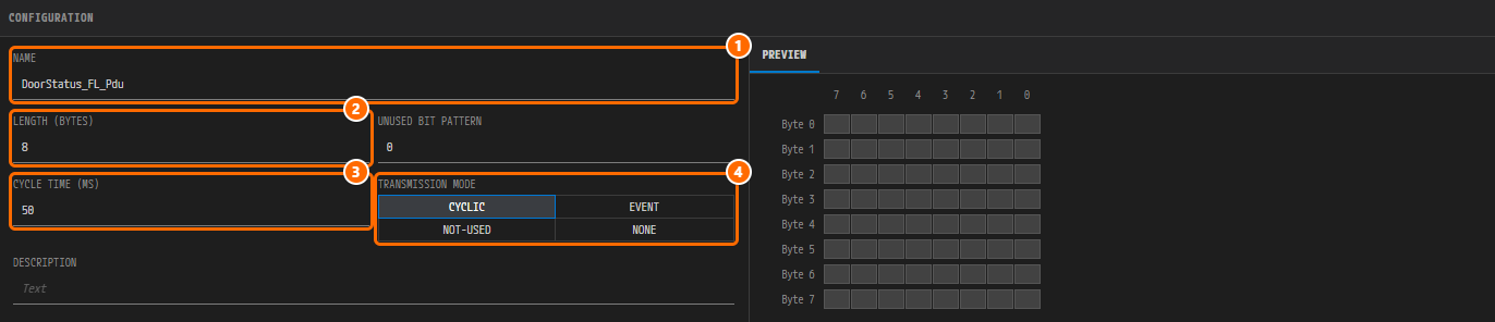
Figure 4-7. The finished PDU. ① NAME =
DoorStatus_FL_Pdu, ② LENGTH (BYTES) =8, ③ CYCLE TIME (MS) =50, ④ TRANSMISSION MODE = CYCLIC. UNUSED BIT PATTERN stays at0. -
Press
Ctrl+Sto save. The dirty marker next to the tab name PNC:Signal disappears. Undo isCtrl+Zand redo isCtrl+Shift+Z.
Note. When you rename a frame, the PDU created with it is renamed too. Renaming
NewFrametoWestCAN_DoorStatus_FLmakes the PDUWestCAN_DoorStatus_FL_Pdu. Four conditions must hold: the frame carries exactly one PDU, that PDU is named{old frame name}_Pdu, that frame is the only one referencing the PDU, and the new name is not yet in use. If a frame carries two or more PDUs, the PDU names stay as they are.
Note. On a frame's PDU REFERENCES tab, the combo box at the right end of the tab bar offers I-Signal I-PDUs as candidates (and N-PDUs, which this example does not have). Use this combo box to attach an existing PDU to another frame, or to attach several PDUs to one frame. If the PDU lengths add up to more than the bytes of the frame's DLC, PAIO raises the DLC to fit them. If they add up to more than 64 bytes (the largest CAN FD payload), the error
Total PDU size ...B exceeds frame max size ...Bappears below the table, and the PDU REFERENCES tab label turns red.
Creating Signals and Mapping Them to a PDU
You create signals from the SIGNALS table while a frame (or a PDU) is selected. A new signal is mapped to the selected PDU right away.
-
On the CAN tab, click
WestCAN_DoorStatus_FL. -
Click + (tooltip Add Signal) right after the SIGNALS title. A signal named after the frame with
_Sigappended (WestCAN_DoorStatus_FL_Sig) is created and mapped to this frame's PDU. The defaults are TYPEUINT, BYTE-ORDERLITTLE-ENDIAN, LENGTH8, FACTOR1, OFFSET0, MIN0, MAX255, INIT VALUE0, and START is the bit after the last signal already mapped. This PDU is still empty, so START is0.
Figure 4-8. Close-up of the SIGNALS table. ① + (tooltip Add Signal) right after the SIGNALS title, ② the added default row
WestCAN_DoorStatus_FL_Sig: START0, LENGTH8, MIN0, MAX255, INIT VALUE0. -
Click a cell in the new row to change its value. When the input field opens, type the value and press
Enterto commit it.Esccancels the input. Edit LENGTH, START and MAX in that order. If you move START while LENGTH is still8, the bits may overlap another signal.
Figure 4-9. The first signal after editing. ① NAME =
DoorOpen_FL, ② LENGTH =1, ③ MAX =0. Leave START at its automatic value0. -
This PDU holds three signals. You changed the first row to
DoorOpen_FLin step 3, so click + once more for each of the remaining two rows and edit their values the same way. Then click the PREVIEW tab in the right column to check the bit layout.NAME LENGTH START MAX DoorOpen_FL10(automatic value, left as is)0DoorLock_FL21(automatic value, left as is)0WindowPos_FL88(typed in)0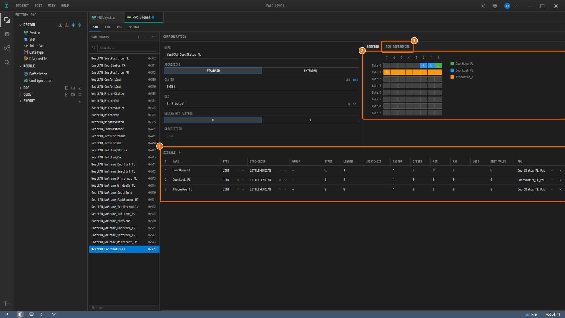
Figure 4-10. The result of mapping three signals. ① The three rows of the SIGNALS table, ② the lower bits of Byte 0 and all of Byte 1 in PREVIEW, with the legend
DoorOpen_FL,DoorLock_FL,WindowPos_FLon the right, ③ the PDU REFERENCES tab, whereDoorStatus_FL_Pdunow has LENGTH8and SIGNALS3. -
Save with
Ctrl+S.
Caution. Changing LENGTH leaves MAX at
255. The signals in this example have both MIN and MAX at0, so set MAX to0yourself.
Caution. The automatic START is not the first free bit but the bit after the last mapping (
0→1→3in the table above). To place the third signalWindowPos_FLat Byte 1, type8into START yourself.
Note. The automatic name of the second and later signals is also
WestCAN_DoorStatus_FL_Sig. Because you rename the previous row first, no number is appended. Work in the order add, rename, add the next.
Creating NM-PDUs
-
On the PDU tab, click + (tooltip Add) to the right of the PDUS header. A two-level menu opens.
Menu group Items Signal I-PDU I-Signal I-PDU, Multiplexed I-PDU Network Mgmt NM-PDU Transport (TP) N-PDU, DCM-I-PDU General Purpose General Purpose PDU 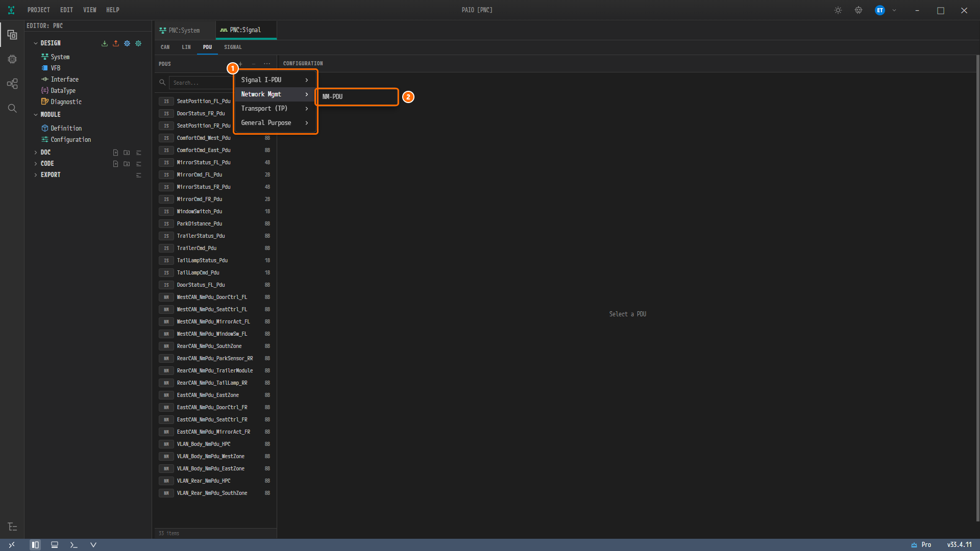
Figure 4-11. The + menu on the PDUS header. ① The four menu groups, ② the submenu item NM-PDU expanded by hovering over Network Mgmt. When the menu opens, the list selection is cleared and "Select a PDU" appears in the center.
-
Hover over Network Mgmt and click NM-PDU.
NewNmPduis created and selected. The defaults are LENGTH (BYTES)8, UNUSED BIT PATTERN0, NM VOTE INFORMATION FALSE and NM DATA INFORMATION FALSE.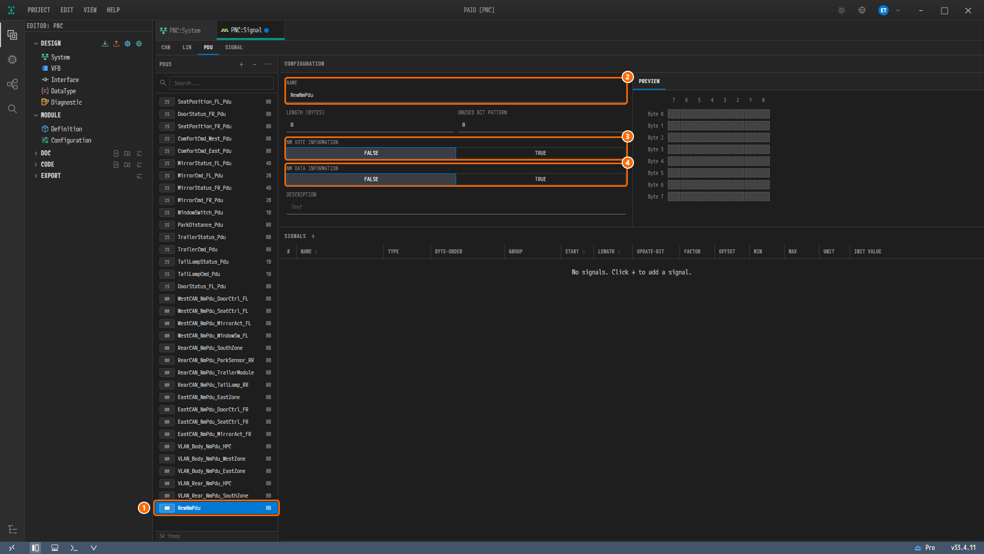
Figure 4-12. Right after creating
NewNmPdu. ①NewNmPduat the bottom of the list (NM tag,8B), ② NAME =NewNmPdu, ③ NM VOTE INFORMATION = FALSE, ④ NM DATA INFORMATION = FALSE. The SIGNALS table shows "No signals. Click + to add a signal." -
Type
WestCAN_NmPdu_WestZonein the NAME field. -
Change NM DATA INFORMATION to TRUE. All 18 NM-PDUs in this example are 8 bytes long with NM VOTE INFORMATION FALSE and NM DATA INFORMATION TRUE.
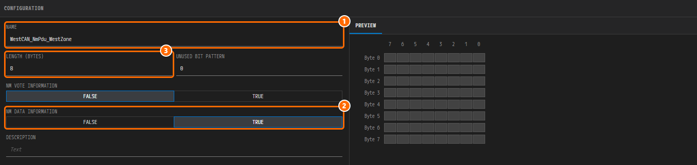
Figure 4-13. The finished NM-PDU. ① NAME =
WestCAN_NmPdu_WestZone, ② NM DATA INFORMATION = TRUE, ③ LENGTH (BYTES) =8. Leave NM VOTE INFORMATION at FALSE. -
The example uses the 18 NM-PDUs in the table below. Create the 17 other than
WestCAN_NmPdu_WestZone, which you built above, the same way and save withCtrl+S.Note. Once you create and save these 18, you can carry out the step deferred in NM Settings of PNC Definitions and Connector PNC Properties. After finishing this chapter, return to Chapter 3 once and fill TX-NM-PDU-REFS and RX-NM-PDU-REFS for each NM node. The second table in All NM Values lists the values per node.
Cluster NM-PDU WestCAN WestCAN_NmPdu_WestZone,WestCAN_NmPdu_DoorCtrl_FL,WestCAN_NmPdu_SeatCtrl_FL,WestCAN_NmPdu_MirrorAct_FL,WestCAN_NmPdu_WindowSw_FLRearCAN RearCAN_NmPdu_SouthZone,RearCAN_NmPdu_ParkSensor_RR,RearCAN_NmPdu_TrailerModule,RearCAN_NmPdu_TailLamp_RREastCAN EastCAN_NmPdu_EastZone,EastCAN_NmPdu_DoorCtrl_FR,EastCAN_NmPdu_SeatCtrl_FR,EastCAN_NmPdu_MirrorAct_FRVLAN_Body VLAN_Body_NmPdu_HPC,VLAN_Body_NmPdu_WestZone,VLAN_Body_NmPdu_EastZoneVLAN_Rear VLAN_Rear_NmPdu_HPC,VLAN_Rear_NmPdu_SouthZone
Caution. In the current version you cannot create NM frames in the Signal editor, because the PDU REFERENCES candidates of a CAN frame are I-Signal I-PDUs (and N-PDUs) and never NM-PDUs. The 13 NM frames in this example are values prepared in the example project or the result of an ARXML import. The I-PDU group work in this chapter does not need NM frames, so if you are building the project yourself, continue without them. Read Looking at an NM Frame below against the example screens.
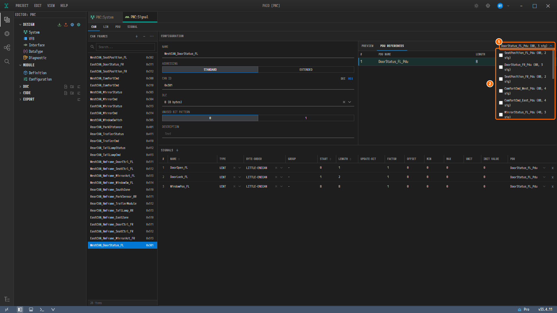
Figure 4-14. The PDU REFERENCES candidates of WestCAN_DoorStatus_FL. ① The combo box at the right end of the tab bar, shown while the PDU REFERENCES tab is selected, ② the expanded candidate list. The candidates are only the 16 I-Signal I-PDUs, in the form name (length, signal count) — for example SeatPosition_FL_Pdu (8B, 2 sig) — and not one NM-PDU appears, including the WestCAN_NmPdu_WestZone you just created. The list is as narrow as the combo box, so long items wrap onto two lines.
Remaining Frames, PDUs and Signals
The example uses the 16 application CAN frames in the table below. Create the 15 other than WestCAN_DoorStatus_FL, which you built above (the second row of the table), the same way. Creating a frame also creates its PDU, so enter the frame name and CAN ID, set the PDU name, length and cycle time, and then map the signals.
- ADDRESSING is STANDARD for all, DLC is
8 (8 bytes)for all, and UNUSED BIT PATTERN is0for all. Even when the PDU length is4,2or1byte, the frame DLC is8. - TRANSMISSION MODE is CYCLIC for every PDU. A new PDU defaults to NONE, so set it on each PDU yourself.
- Every signal has TYPE
UINT, BYTE-ORDERLITTLE-ENDIAN, FACTOR1, OFFSET0, MIN0, MAX0and INIT VALUE0.
Note. The 16 application frames in this example are marked as CAN FD frames in the model, but the Signal editor in the current version has no frame-level CAN FD field, so you can neither check nor change it on screen. This value is separate from configuring the controller as CAN FD in Chapter 2, and it does not affect the work in this chapter.
| Frame | CAN ID | PDU | PDU length (B) | Cycle time (ms) | Signals (START, LENGTH) |
|---|---|---|---|---|---|
WestCAN_ComfortCmd | 0x300 | ComfortCmd_West_Pdu | 8 | 20 | LockCmd_FL(0, 2), WindowCmd_FL(2, 4), SeatMoveCmd_FL(8, 4), SeatHeatCmd_FL(12, 2) |
WestCAN_DoorStatus_FL | 0x301 | DoorStatus_FL_Pdu | 8 | 50 | DoorOpen_FL(0, 1), DoorLock_FL(1, 2), WindowPos_FL(8, 8) |
WestCAN_SeatPosition_FL | 0x302 | SeatPosition_FL_Pdu | 8 | 100 | SeatPos_FL(0, 8), SeatHeat_FL(8, 2) |
WestCAN_MirrorStatus | 0x303 | MirrorStatus_FL_Pdu | 4 | 100 | MirrorFoldSts_FL(0, 2), MirrorTiltX_FL(8, 8), MirrorTiltY_FL(16, 8) |
WestCAN_MirrorCmd | 0x304 | MirrorCmd_FL_Pdu | 2 | 100 | MirrorFoldCmd_FL(0, 2), MirrorMoveCmd_FL(2, 4) |
WestCAN_WindowSwitch | 0x305 | WindowSwitch_Pdu | 1 | 100 | WindowSwUp(0, 1), WindowSwDown(1, 1), WindowSwAuto(2, 1) |
EastCAN_ComfortCmd | 0x310 | ComfortCmd_East_Pdu | 8 | 20 | LockCmd_FR(0, 2), WindowCmd_FR(2, 4), SeatMoveCmd_FR(8, 4), SeatHeatCmd_FR(12, 2) |
EastCAN_DoorStatus_FR | 0x311 | DoorStatus_FR_Pdu | 8 | 50 | DoorOpen_FR(0, 1), DoorLock_FR(1, 2), WindowPos_FR(8, 8) |
EastCAN_SeatPosition_FR | 0x312 | SeatPosition_FR_Pdu | 8 | 100 | SeatPos_FR(0, 8), SeatHeat_FR(8, 2) |
EastCAN_MirrorStatus | 0x313 | MirrorStatus_FR_Pdu | 4 | 100 | MirrorFoldSts_FR(0, 2), MirrorTiltX_FR(8, 8), MirrorTiltY_FR(16, 8) |
EastCAN_MirrorCmd | 0x314 | MirrorCmd_FR_Pdu | 2 | 100 | MirrorFoldCmd_FR(0, 2), MirrorMoveCmd_FR(2, 4) |
RearCAN_ParkDistance | 0x401 | ParkDistance_Pdu | 8 | 50 | ParkDist_1(0, 8), ParkDist_2(8, 8), ParkDist_3(16, 8), ParkDist_4(24, 8), ParkSensorFault(32, 1) |
RearCAN_TrailerCmd | 0x410 | TrailerCmd_Pdu | 8 | 50 | TrailerLampCmd(0, 8) |
RearCAN_TrailerStatus | 0x411 | TrailerStatus_Pdu | 8 | 100 | TrailerAttached(0, 1), TrailerLampFault(1, 4), TrailerBrakeLamp(5, 1) |
RearCAN_TailLampStatus | 0x412 | TailLampStatus_Pdu | 1 | 100 | TailLampSts(0, 4) |
RearCAN_TailLampCmd | 0x413 | TailLampCmd_Pdu | 1 | 100 | TailLampCmd(0, 4) |
This table yields 16 application CAN frames, 16 I-Signal I-PDUs and 42 signals. Add the 18 NM-PDUs from Creating NM-PDUs and the 13 NM frames prepared in the example, and you reach the state shown in the screens of the sections below (29 frames, 34 PDUs, 42 signals).
Once everything is entered, save with Ctrl+S.
Looking at a CAN Frame
-
In the CAN FRAMES list on the CAN tab, click
WestCAN_DoorStatus_FL. Each row shows its CAN ID on the right, and "29 items" appears below the list ("16 items" in a project without NM frames). In the right column, click the PREVIEW tab.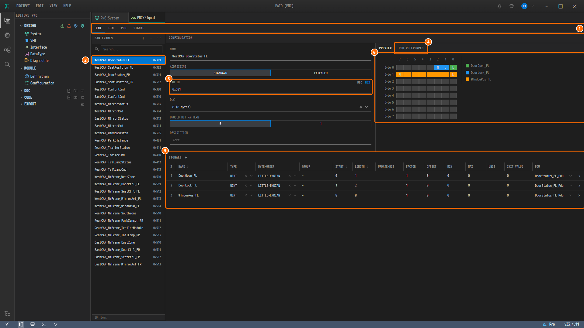
Figure 4-15. The CAN tab. ① The protocol tab row, ② the list row
WestCAN_DoorStatus_FL0x301, ③ CAN ID =0x301, ④ the PDU REFERENCES tab, ⑤ the SIGNALS table, ⑥ the selected PREVIEW tab. -
Check the frame properties in CONFIGURATION, then click the PDU REFERENCES tab to see the PDU the frame carries.
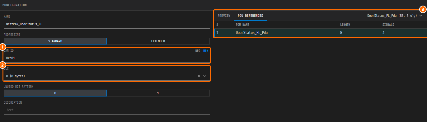
Figure 4-16. Close-up of CONFIGURATION. ① CAN ID =
0x301(the DEC | HEX switch to the right of the label, HEX by default), ② DLC =8 (8 bytes), ③ the PDU REFERENCES tab. The table listsDoorStatus_FL_Pdu(LENGTH8, SIGNALS3), and the combo box at the right end of the tab bar showsDoorStatus_FL_Pdu (8B, 3 sig).Field Value NAME WestCAN_DoorStatus_FLADDRESSING STANDARD CAN ID 0x301DLC 8 (8 bytes)UNUSED BIT PATTERN 0 -
Check the signals mapped to this frame's PDU in the SIGNALS table below. The PREVIEW tab (Figure 4-15) shows the signals in color on a grid of Byte 0–7 × bit 7–0, with a legend to its right.
NAME START LENGTH DoorOpen_FL01DoorLock_FL12WindowPos_FL88
Looking at a PDU
-
Click the PDU tab. The list title changes to PDUS and 34 items appear. The IS tag at the left of a row marks an I-Signal I-PDU (16 of them) and the NM tag an NM-PDU (18 of them). The length (
8B,4B,2B,1B) is appended at the right of each row. -
Click
DoorStatus_FL_Pdu.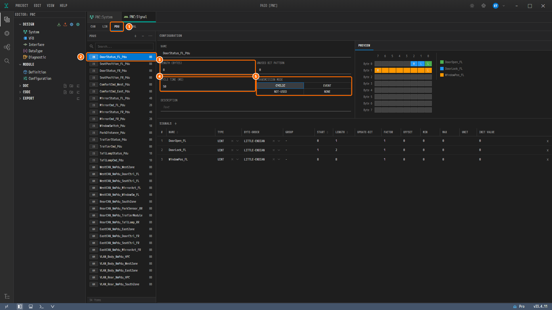
Figure 4-17. The PDU tab. ① The PDU tab, ②
DoorStatus_FL_Pdu(IS tag), ③ LENGTH (BYTES) =8, ④ CYCLE TIME (MS) =50, ⑤ TRANSMISSION MODE = CYCLIC. UNUSED BIT PATTERN is0, and the SIGNALS table holds three signals. -
In the list, click
WestCAN_NmPdu_WestZone, which carries the NM tag. An NM-PDU has the fields NM VOTE INFORMATION and NM DATA INFORMATION, and no signals.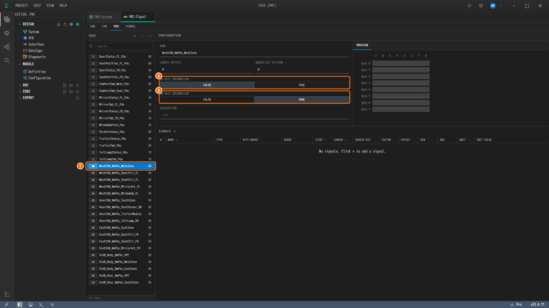
Figure 4-18. An NM-PDU. ①
WestCAN_NmPdu_WestZone, ② NM VOTE INFORMATION = FALSE, ③ NM DATA INFORMATION = TRUE. LENGTH (BYTES) is8, and the SIGNALS table shows "No signals. Click + to add a signal."Note. All 18 NM-PDUs in this example are 8 bytes long with NM VOTE INFORMATION = FALSE and NM DATA INFORMATION = TRUE. Five of them (
VLAN_Body_NmPdu_*,VLAN_Rear_NmPdu_*) are for Ethernet VLANs and therefore have no CAN frame.
Looking at a Signal
-
Click the SIGNAL tab. The list title changes to SIGNALS and 42 items appear. The bit length (
1bit,2bit, and so on) is appended at the right of each row. -
Click
DoorOpen_FL.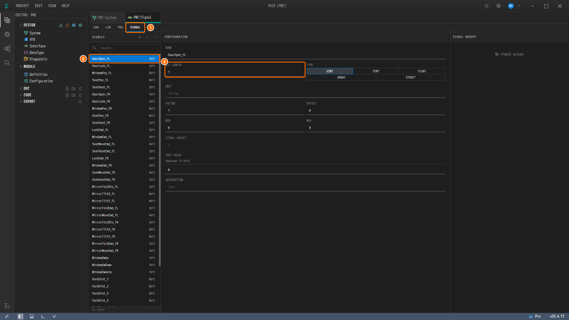
Figure 4-19. The SIGNAL tab. ① The SIGNAL tab, ②
DoorOpen_FL(1bit), ③ BIT LENGTH =1. TYPE is UINT, with FACTOR1, OFFSET0, MIN0and MAX0, and INIT VALUE shows the noteboolean (1-bit)with the value0. The right panel is SIGNAL GROUPS ("No signal groups").
Looking at an NM Frame
The NM frames are prepared in the example project. If a project you built yourself has no NM frames, read this section only to see how the screen is laid out (see the caution in Creating NM-PDUs).
-
Click the CAN tab, then click
WestCAN_NmFrame_WestZone(0x510) in the list. The PDU REFERENCES tab you clicked in Looking at a CAN Frame is still selected.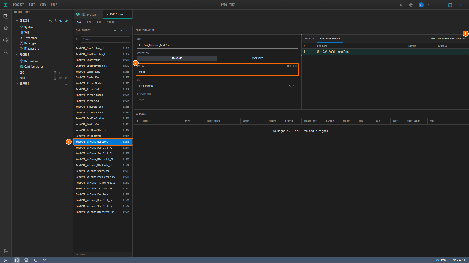
Figure 4-20. An NM frame. ① The list row
WestCAN_NmFrame_WestZone0x510, ② CAN ID =0x510, ③WestCAN_NmPdu_WestZoneon the PDU REFERENCES tab. Because it points to an NM-PDU, LENGTH and SIGNALS are shown as-.Note. When you select an NM frame, the UNUSED BIT PATTERN field does not appear. This is how the current version displays it, and the stored values are unaffected. The PREVIEW tab shows the empty 8-byte grid of the NM-PDU, because an NM-PDU carries no signals.
The NM frames in this example are numbered from 0x510 in node order within each cluster. The names follow {cluster}_NmFrame_{node}, and each frame carries the {cluster}_NmPdu_{node} of the same node.
| Cluster | 0x510 | 0x511 | 0x512 | 0x513 | 0x514 |
|---|---|---|---|---|---|
| WestCAN | WestZone | DoorCtrl_FL | SeatCtrl_FL | MirrorAct_FL | WindowSw_FL |
| RearCAN | SouthZone | ParkSensor_RR | TrailerModule | TailLamp_RR | — |
| EastCAN | EastZone | DoorCtrl_FR | SeatCtrl_FR | MirrorAct_FR | — |
Design rationale. In Chapter 3 you entered PNC WAKEUP CAN ID
0x500and PNC WAKEUP CAN ID MASK0x700on the Zone CAN connectors. That combination treats frames in the0x500..0x5FFblock as wakeup frames. The NM frames above (0x510..0x514) all fall inside that block and are therefore recognized as wakeup frames. AUTOSAR does not reserve a CAN ID range for NM; this range follows OEM network design practice.
Practice: Adding a Signal
This section revisits the operations from Creating Signals and Mapping Them to a PDU on a PDU that already holds signals. The ChildLock_FL you add here does not exist in the example, so you discard it instead of saving when the practice is over. You already saved the work of the previous sections with Ctrl+S, so the only thing discarded here is the practice signal.
-
On the CAN tab, click
WestCAN_DoorStatus_FL, then click the PREVIEW tab in the right column. -
Click + (tooltip Add Signal) right after the SIGNALS title.

Figure 4-21. Close-up of the SIGNALS table. ① + (Add Signal).
-
WestCAN_DoorStatus_FL_Sigis added as the fourth row. The name is generated automatically by appending_Sigto the frame name. The defaults are START16, LENGTH8and MAX255. SIGNALS on the PDU REFERENCES tab changes to4, and a dirty marker appears next to the tab name PNC:Signal.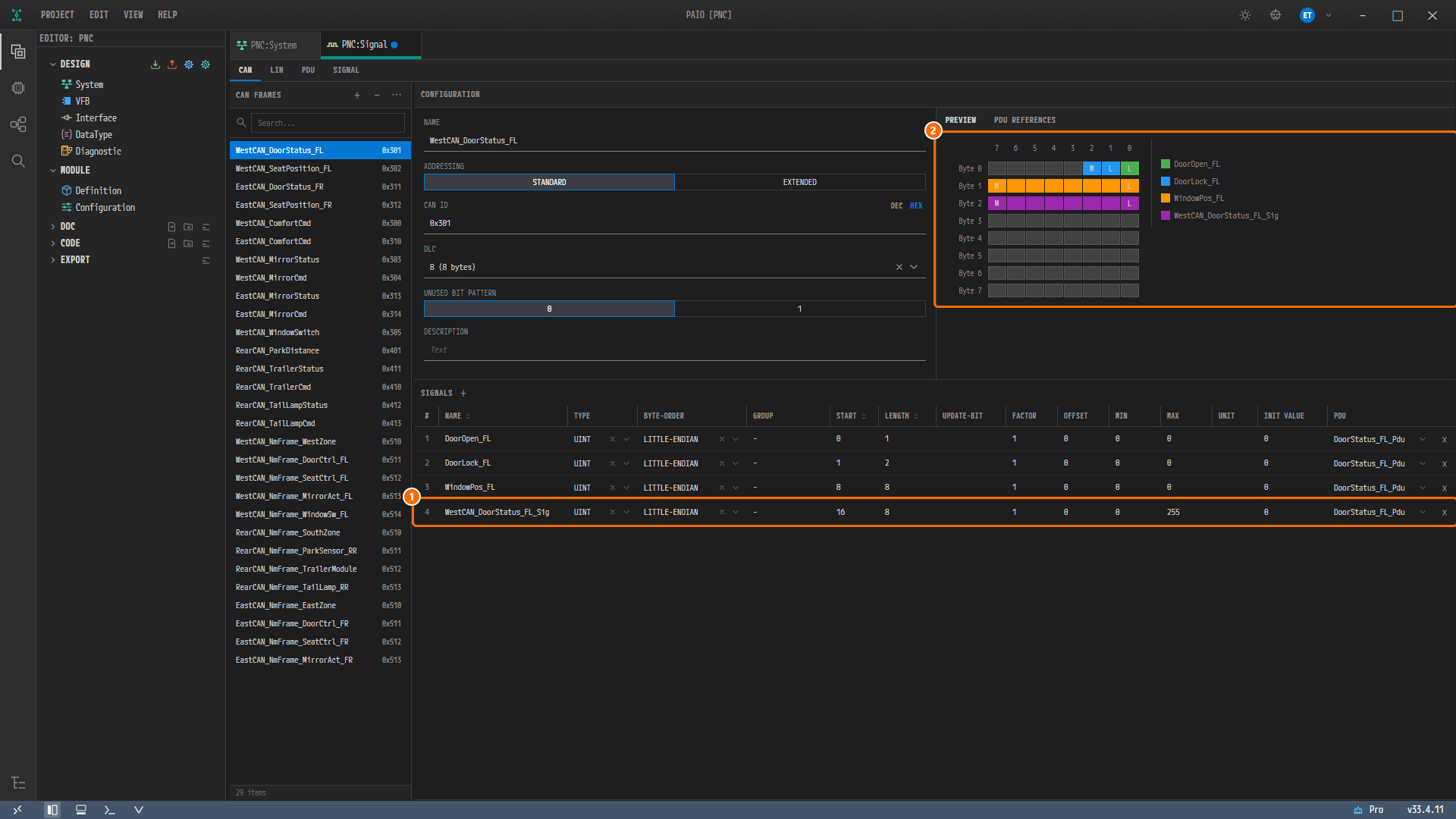
Figure 4-22. Right after clicking +. ① The new row
WestCAN_DoorStatus_FL_Sig, ② all of Byte 2 in PREVIEW shown in the new signal's color. -
Click the NAME cell of the new row. When the input field opens, type
ChildLock_FLand pressEnter.Esccancels the input.
Figure 4-23. ① Typing
ChildLock_FLinto the NAME input field. -
Click the LENGTH cell, type
2and pressEnter. In PREVIEW, only bits 1–0 of Byte 2 turn theChildLock_FLcolor.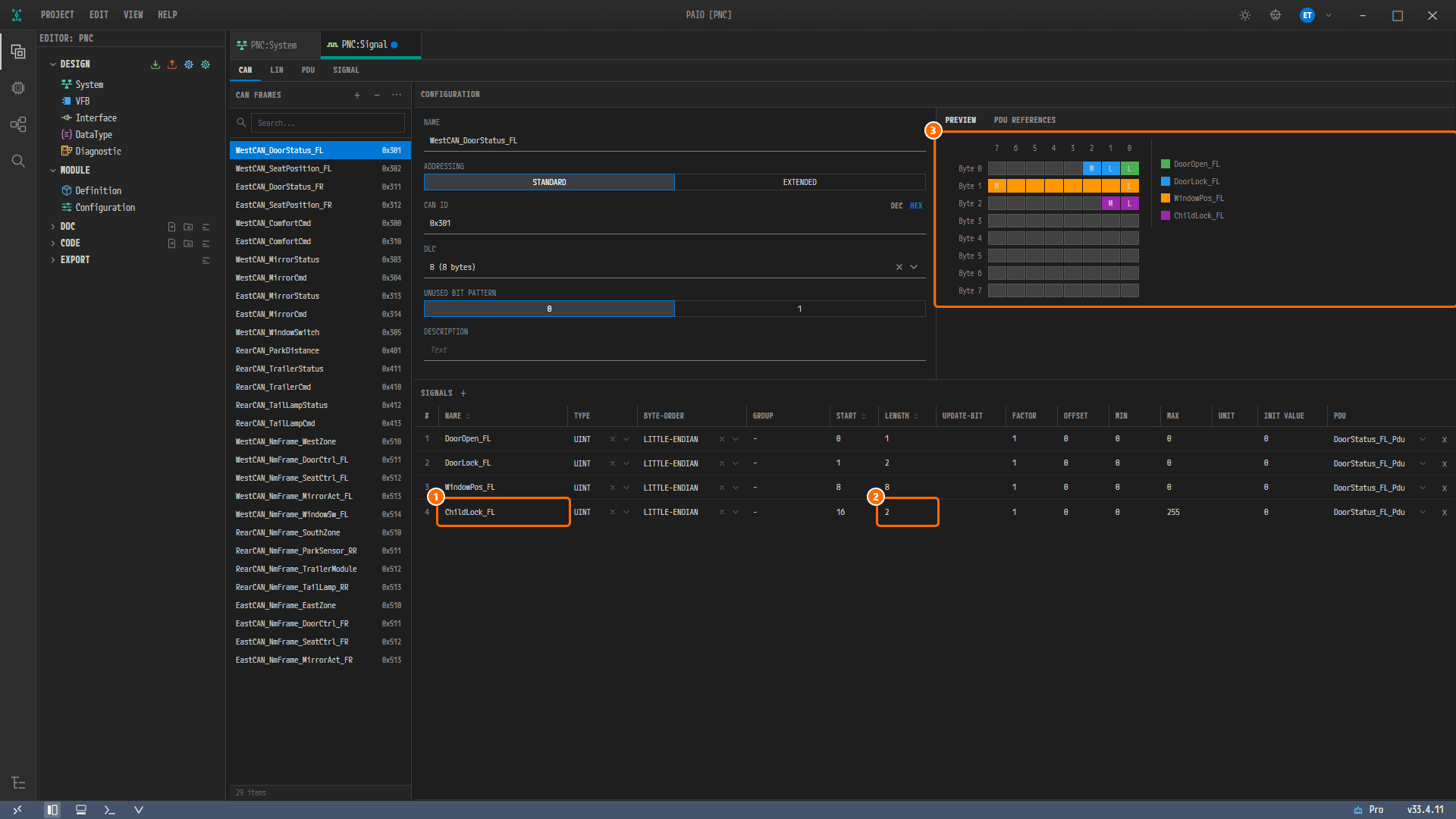
Figure 4-24. ① NAME =
ChildLock_FL, ② LENGTH =2, ③ bits 1–0 of Byte 2 in PREVIEW.Caution. Changing LENGTH leaves MAX at
255. Edit MAX yourself if you need to. A new signal is also placed after the last signal (START16here) rather than at the first free bit. Bits 3–7 ofDoorStatus_FL_Pduare free, but a signal is not placed there automatically, so type START yourself if you have a position in mind.Note.
Ctrl+Zalso undoes the added signal. Redo isCtrl+Shift+Z. -
When the practice is over, click × (tooltip Remove Signal) at the right end of the row to delete the
ChildLock_FLrow. -
Hover over the PNC:Signal tab and click the × (tooltip Close) that appears to close the tab. When the Unsaved Changes window appears, click Don't Save. The practice is not saved and is discarded entirely.
Caution. If you leave the Signal editor open in a dirty state (the marker next to the tab name) and then save the PNC dialog in the next section, PAIO applies the groups to the open Signal editor and saves that editor's contents along with them. To keep your practice edits from being saved, be sure to close the tab without saving before you open the PNC dialog.
Creating I-PDU Groups
You create I-PDU groups in the PNC dialog. As the representative case, create the WestCAN receive group WestCAN_PNC_Comfort_Rx of PNC_Comfort and put DoorStatus_FL_Pdu into it.
Creating the Group
-
In the EDITOR view on the left, click System under DESIGN to open the System editor (tab PNC:System).
-
In the vertical icon strip along the left edge of the canvas, click the second (lower) icon, Partial Network (PNC) (Figure 3-1). The Partial Network (PNC) Configuration dialog opens.
-
Confirm that PNC 17 PNC_Comfort is selected in the PARTIAL NETWORKS list. PNC GROUPS in the center is empty.
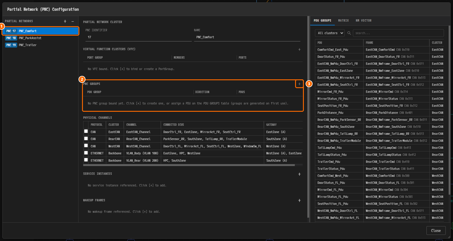
Figure 4-25. The PNC dialog. The right panel is divided into the PDU GROUPS / MATRIX / NM VECTOR tabs, with PDU GROUPS selected. ① PNC 17 PNC_Comfort, ② the PNC GROUPS section (columns PDU GROUP / DIRECTION / PDUS). It shows "No PNC group bound yet. Click [+] to create one, or assign a PDU on the PDU GROUPS table (groups are generated on first use)." ③ + (tooltip Add I-PDU group to this PNC).
-
Click the + button to the right of the PNC GROUPS header. In the menu, click New Rx group....
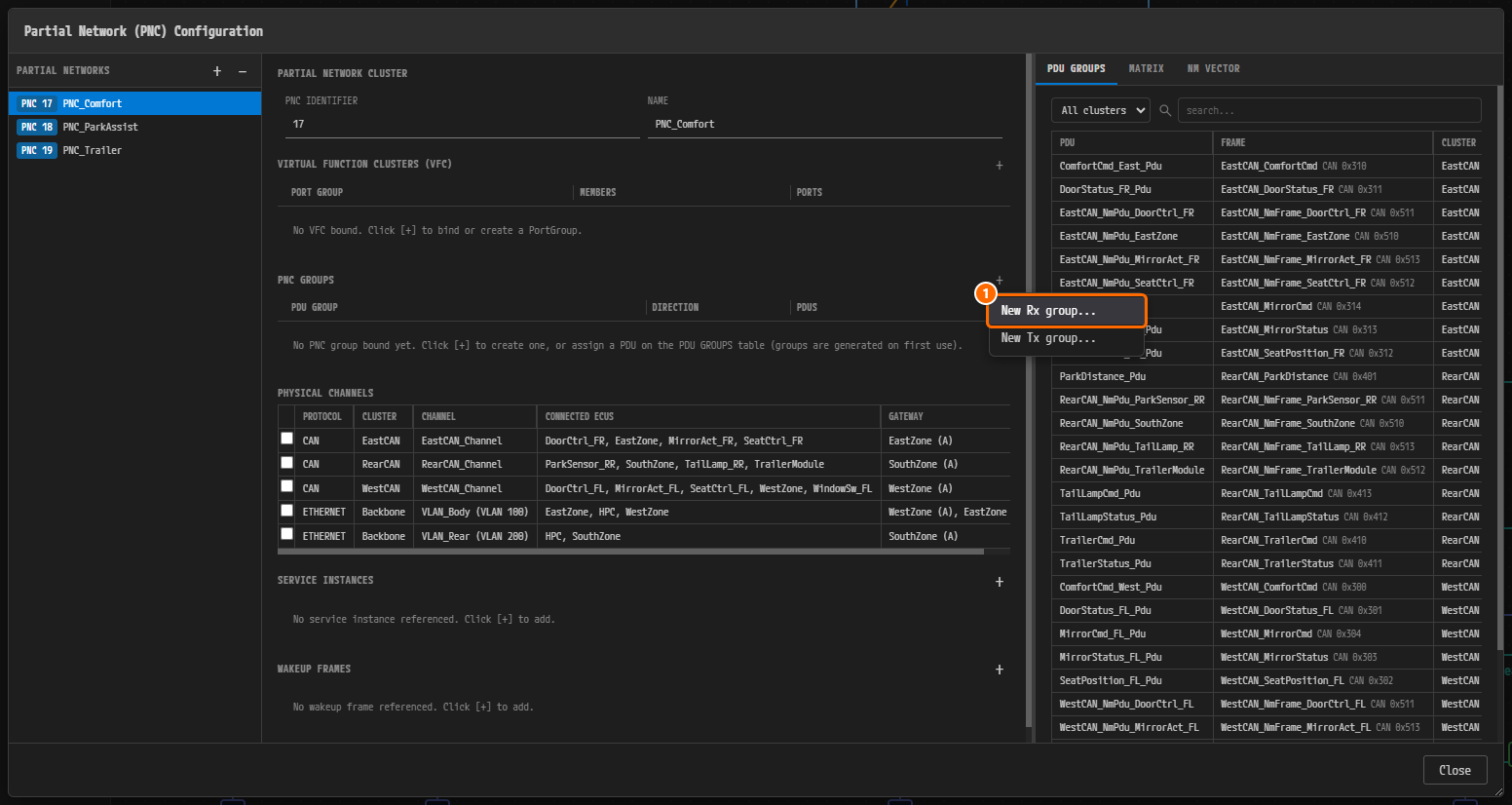
Figure 4-26. The + menu. ① New Rx group.... The New Tx group... item below it creates a transmit group.
-
The New Rx I-PDU group input window opens. Type
WestCAN_PNC_Comfort_Rxand click OK.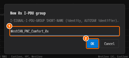
Figure 4-27. The input window. The guidance text reads "I-SIGNAL-I-PDU-GROUP SHORT-NAME (identity, AUTOSAR identifier)." ① The name field, ② OK.
Note. The placeholder in the field is
Cluster_PNC_Rx. PAIO checks only whether the name is a valid AUTOSAR identifier and whether it is a duplicate; it does not enforce the Naming Convention below. Type the name according to the convention yourself. -
The row
WestCAN_PNC_Comfort_Rx| RX |0 PDUsappears in PNC GROUPS and expands automatically. A ● marker is prefixed to the dialog title.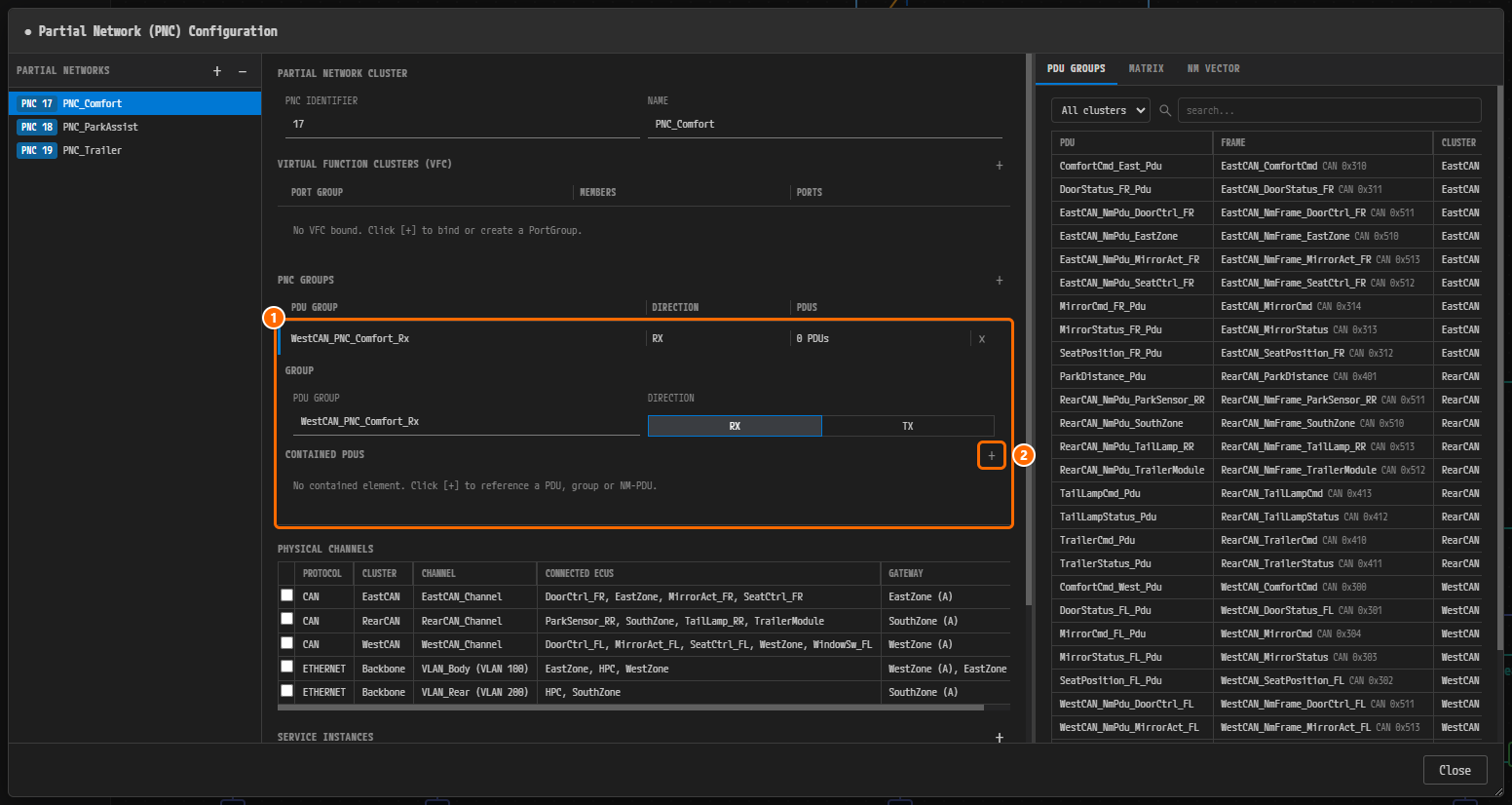
Figure 4-28. ① The new group row and its detail. The GROUP section holds PDU GROUP (the name) and DIRECTION (RX / TX), and CONTAINED PDUS shows "No contained element. Click [+] to reference a PDU, group or NM-PDU." ② The + of CONTAINED PDUS.
Note. A group created with the + button of PNC GROUPS is bound immediately to the PNC that was selected at the time. To create a group for another PNC, first select that PNC in the PARTIAL NETWORKS list.
Putting PDUs into the Group
-
Click + (tooltip Add contained element) to the right of the CONTAINED PDUS header. A new row appears. The columns are # / KIND / REFERENCE / FRAME / FRAME ID / CLUSTER, and KIND defaults to I-SIGNAL-I-PDU. Until you pick a PDU, the REFERENCE field is marked red (tooltip
Reference is required). -
Click the REFERENCE cell of the new row and type
DoorStatus. The candidates narrow toDoorStatus_FR_PduandDoorStatus_FL_Pdu.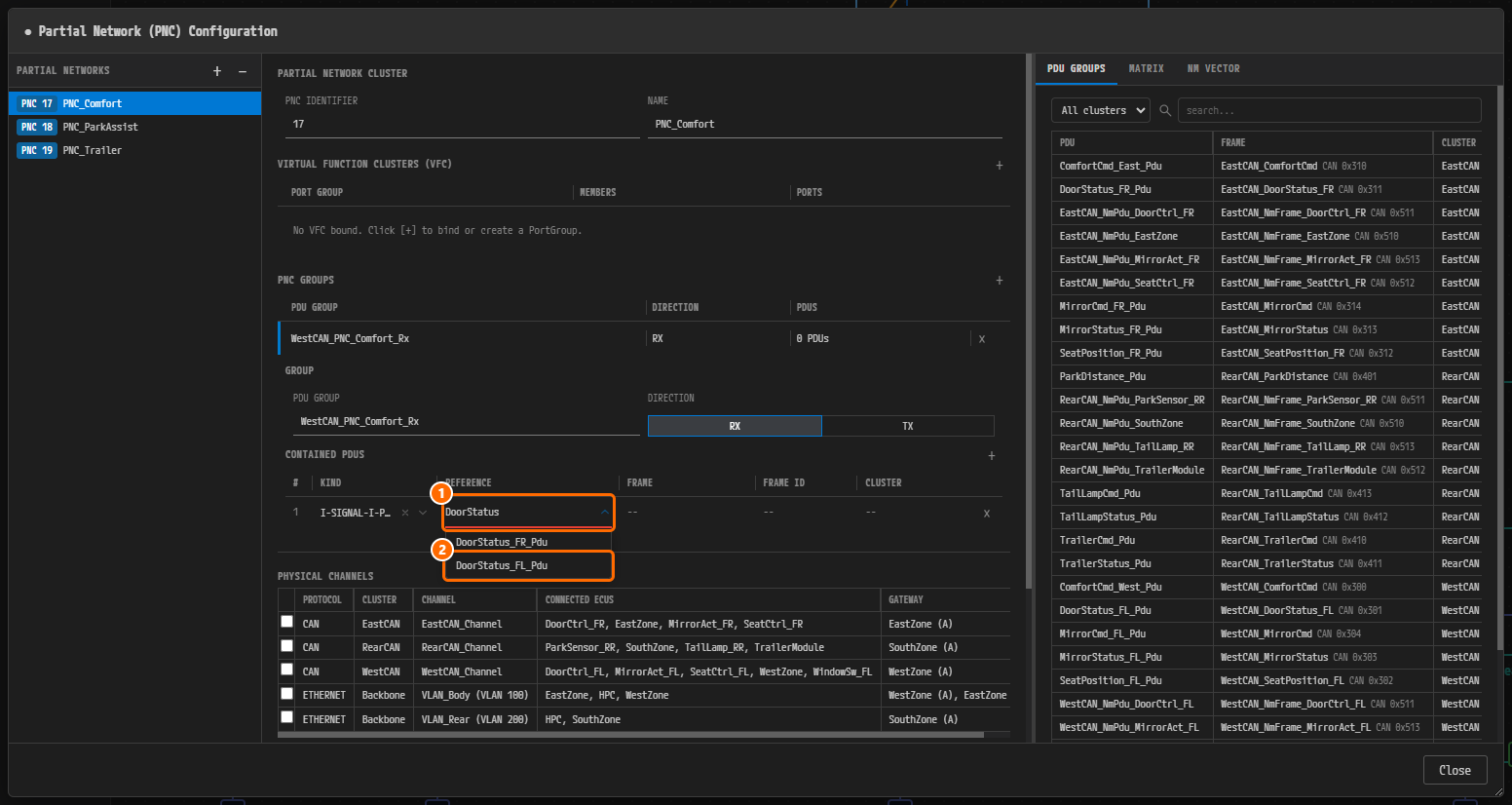
Figure 4-29. ①
DoorStatustyped into the REFERENCE cell, ② the candidateDoorStatus_FL_Pdu. The KIND cell is narrow, so it is truncated toI-SIGNAL-I-P…. -
Click
DoorStatus_FL_Pdu. FRAME, FRAME ID and CLUSTER are filled in automatically, and PDUS on the group row changes to1 PDU. In the PDU GROUPS table on the right, theDoorStatus_FL_Pdurow is highlighted.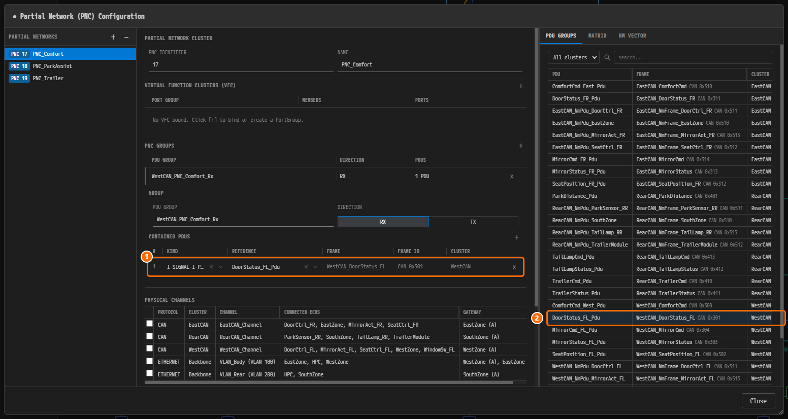
Figure 4-30. ① The CONTAINED PDUS row:
DoorStatus_FL_Pdu/WestCAN_DoorStatus_FL/CAN 0x301/WestCAN, ② theDoorStatus_FL_Pdurow in the PDU GROUPS table on the right. -
Press
Ctrl+Sto save. The ● marker before the title disappears.
Note. When you save from the PNC dialog, the groups themselves are written to the SIGNAL model (
SIGNAL.io.model) and the links between the PNCs and the groups to the SYSTEM model (SYSTEM.io.model). No dirty marker appears on the System editor tab (PNC:System).
Caution. The REFERENCE candidates for KIND = I-SIGNAL-I-PDU include CAN NM-PDUs (
WestCAN_NmPdu_*and so on) mixed in with the I-Signal I-PDUs. Do not put NM-PDUs into a PNC group (see Why Is It Designed This Way?). Pick only the application PDUs whose names end in_Pdu.
Caution. The × button at the right end of a group row does not merely unbind the group from the PNC — it deletes the group itself. If the group is bound to other PNCs as well, a delete confirmation window appears first.
Creating the Remaining Groups
Create every group in the table below the same way and put its PDUs in.
- First, add the remaining three PDUs (
SeatPosition_FL_Pdu,MirrorStatus_FL_Pdu,WindowSwitch_Pdu) to theWestCAN_PNC_Comfort_Rxyou built above. Click the group row to expand it, then click the + button of CONTAINED PDUS once per PDU. - Create receive groups with New Rx group... and transmit groups with New Tx group....
- Select the relevant PNC in the PARTIAL NETWORKS list before you create a group.
- For
RearCAN_PNC_ParkAssist_Tx, create the group only and put no PDU in it.
| PNC | Group | DIRECTION | CONTAINED PDUS |
|---|---|---|---|
PNC 17 PNC_Comfort | WestCAN_PNC_Comfort_Rx | RX | DoorStatus_FL_Pdu, SeatPosition_FL_Pdu, MirrorStatus_FL_Pdu, WindowSwitch_Pdu |
PNC 17 PNC_Comfort | WestCAN_PNC_Comfort_Tx | TX | ComfortCmd_West_Pdu, MirrorCmd_FL_Pdu |
PNC 17 PNC_Comfort | EastCAN_PNC_Comfort_Rx | RX | DoorStatus_FR_Pdu, SeatPosition_FR_Pdu, MirrorStatus_FR_Pdu |
PNC 17 PNC_Comfort | EastCAN_PNC_Comfort_Tx | TX | ComfortCmd_East_Pdu, MirrorCmd_FR_Pdu |
PNC 18 PNC_ParkAssist | RearCAN_PNC_ParkAssist_Rx | RX | ParkDistance_Pdu |
PNC 18 PNC_ParkAssist | RearCAN_PNC_ParkAssist_Tx | TX | (none) |
PNC 19 PNC_Trailer | RearCAN_PNC_Trailer_Rx | RX | TrailerStatus_Pdu, TailLampStatus_Pdu |
PNC 19 PNC_Trailer | RearCAN_PNC_Trailer_Tx | TX | TrailerCmd_Pdu, TailLampCmd_Pdu |
Once everything is entered, save with Ctrl+S and click Close to close the dialog.
The Finished Result
In the finished example, the Signal editor and the PNC dialog look as follows.
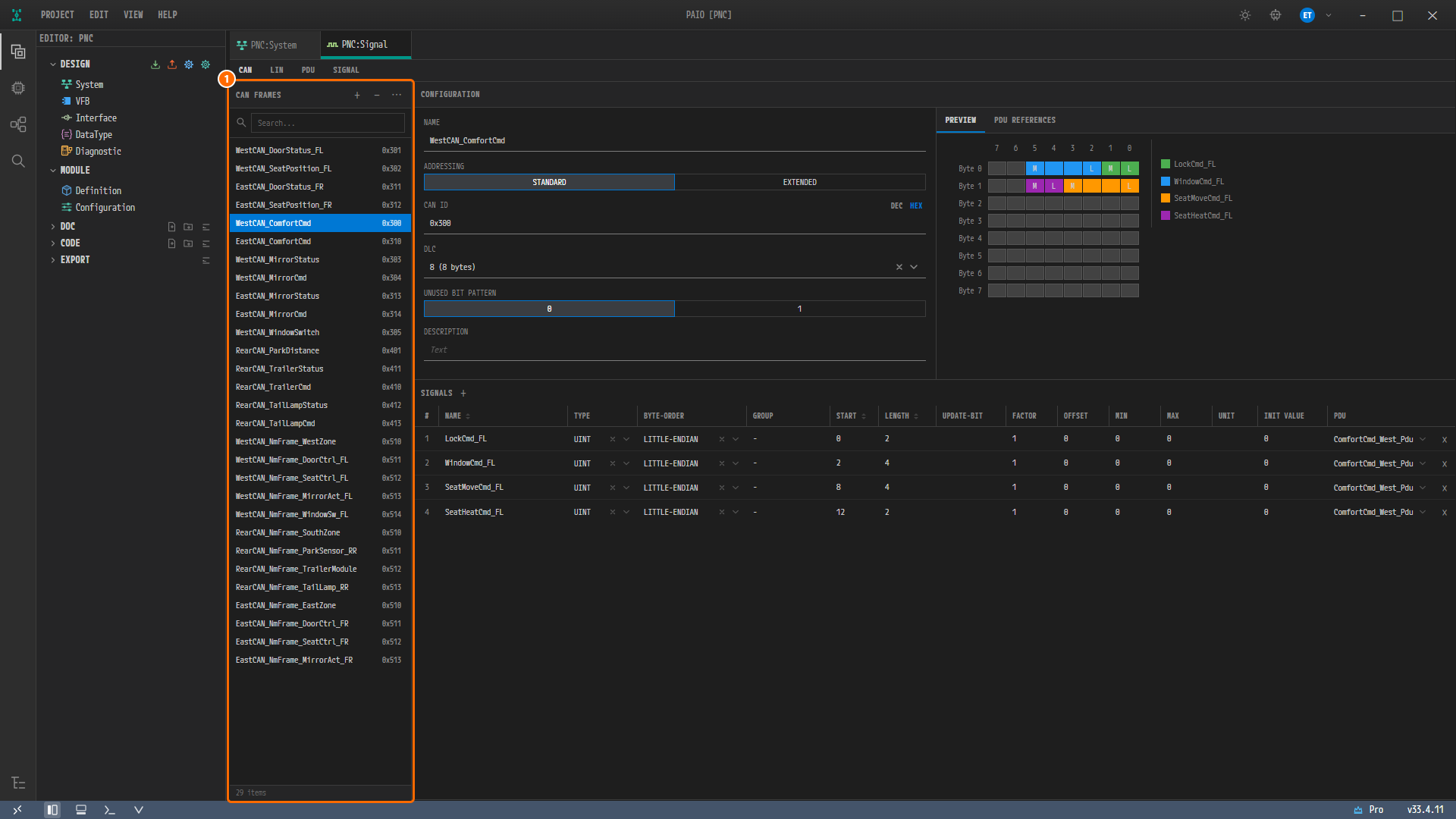
Figure 4-31. The Signal editor in the finished example. ① The CAN FRAMES list (29 items). The selected WestCAN_ComfortCmd (0x300) carries ComfortCmd_West_Pdu, and its signals are LockCmd_FL (START 0, LENGTH 2), WindowCmd_FL (2, 4), SeatMoveCmd_FL (8, 4) and SeatHeatCmd_FL (12, 2). PREVIEW shows them in Byte 0 and Byte 1.
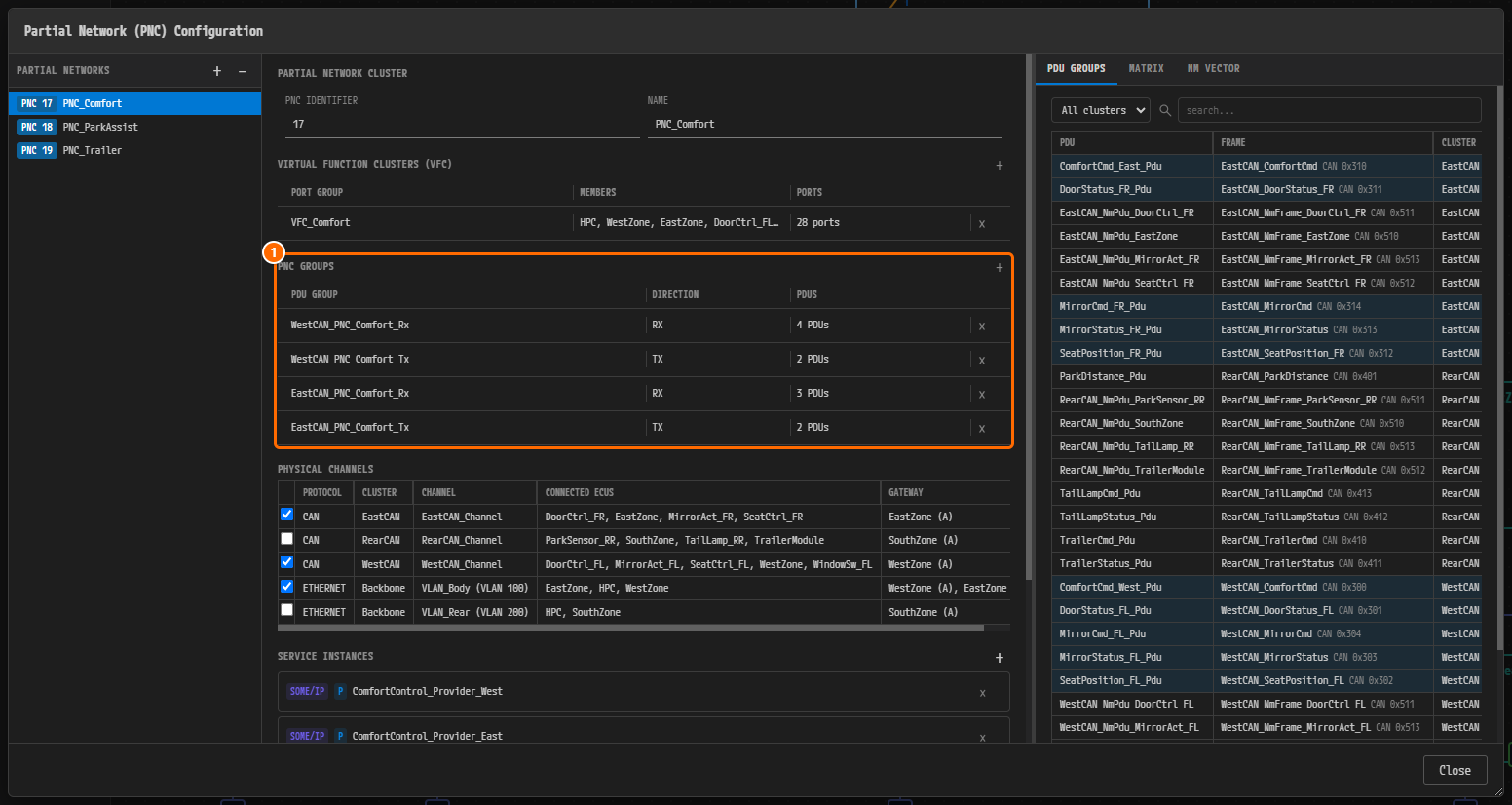
Figure 4-32. PNC 17 PNC_Comfort in the finished example. ① PNC GROUPS: WestCAN_PNC_Comfort_Rx (RX, 4 PDUs), WestCAN_PNC_Comfort_Tx (TX, 2 PDUs), EastCAN_PNC_Comfort_Rx (RX, 3 PDUs), EastCAN_PNC_Comfort_Tx (TX, 2 PDUs). VIRTUAL FUNCTION CLUSTERS (VFC), PHYSICAL CHANNELS, SERVICE INSTANCES and the WAKEUP FRAMES below them are filled in PNC Dialog — Per-PNC Bindings.
Click a group row to expand it and see its CONTAINED PDUS.
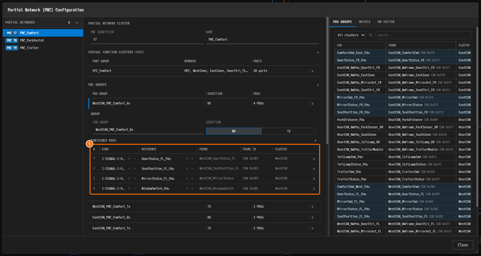
Figure 4-33. WestCAN_PNC_Comfort_Rx expanded. ① The four CONTAINED PDUS rows: DoorStatus_FL_Pdu (CAN 0x301), SeatPosition_FL_Pdu (CAN 0x302), MirrorStatus_FL_Pdu (CAN 0x303), WindowSwitch_Pdu (CAN 0x305). All have CLUSTER WestCAN.
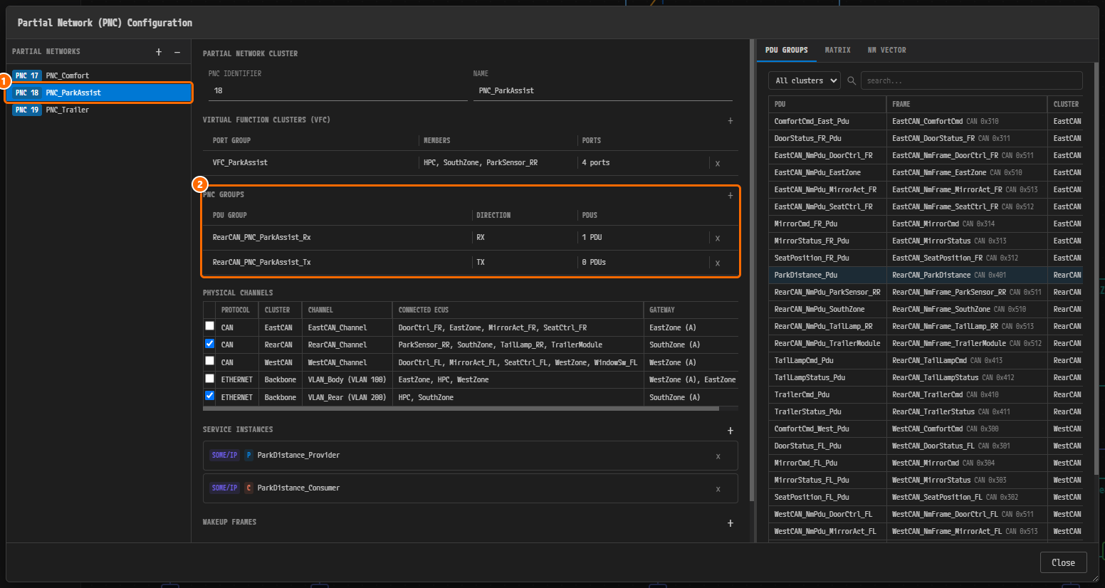
Figure 4-34. PNC 18 PNC_ParkAssist in the finished example. ① PNC 18 PNC_ParkAssist, ② PNC GROUPS: RearCAN_PNC_ParkAssist_Rx (RX, 1 PDU), RearCAN_PNC_ParkAssist_Tx (TX, 0 PDUs).
Naming Convention
PAIO derives the SHORT-NAME of an I-PDU group from the structure by convention. ARXML import and export normalize to the same convention, so the example uses these names as they are.
| Form | Name | Example | Contents in this example |
|---|---|---|---|
| Container | {cluster}_Rx / {cluster}_Tx | RearCAN_Rx | Holds RearCAN_PNC_ParkAssist_Rx, RearCAN_PNC_Trailer_Rx and RearCAN_NoPnc_Rx. |
| PNC leaf | {cluster}_{pnc}_Rx / {cluster}_{pnc}_Tx | WestCAN_PNC_Comfort_Rx | Holds the PDUs that belong to that PNC on that bus. |
| Non-participating leaf | {cluster}_NoPnc_Rx / {cluster}_NoPnc_Tx | WestCAN_NoPnc_Tx | Holds the PDUs that belong to no PNC. In this example every application PDU belongs to a PNC, so these are empty. |
| NM-PDU | {cluster}_NmPdu_{node} | WestCAN_NmPdu_WestZone | One per node, 8 bytes |
| NM frame | {cluster}_NmFrame_{node} | WestCAN_NmFrame_WestZone | Numbered from 0x510 in node order |
- The direction (
_Rx/_Tx) is from the Zone (gateway) point of view. A status PDU sent by an end ECU (for exampleDoorStatus_FL_Pdu) is received by the Zone and is therefore_Rx, while a command PDU the Zone sends down to an end ECU (for exampleComfortCmd_West_Pdu) is_Tx. - Only the PNC leaf groups are bound to a PNC. The container and NoPnc groups are bound to no PNC.
Container groups and NoPnc groups do not appear in PNC GROUPS, because PNC GROUPS shows only the groups bound to the selected PNC. In the finished example you can see their names in the candidate list by adding a row to CONTAINED PDUS, changing KIND to GROUP and typing a name into REFERENCE.
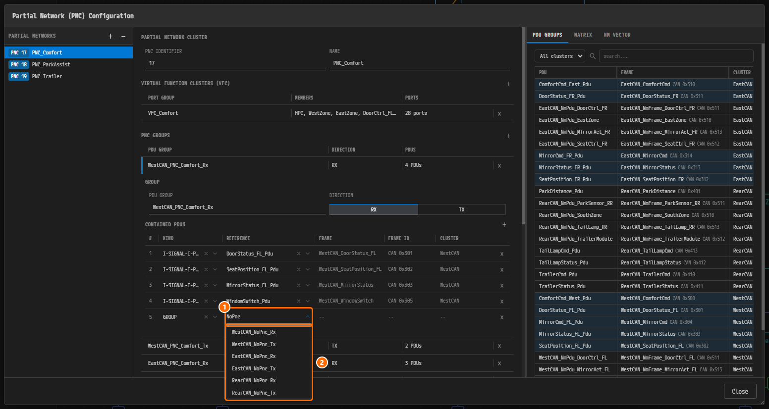
Figure 4-35. NoPnc typed into REFERENCE on a KIND = GROUP row in the finished example. ① The REFERENCE cell, ② the candidates WestCAN_NoPnc_Rx, WestCAN_NoPnc_Tx, EastCAN_NoPnc_Rx, EastCAN_NoPnc_Tx, RearCAN_NoPnc_Rx, RearCAN_NoPnc_Tx. This screen is for inspection only, so close it with Esc without picking a candidate, then delete the row with the × (tooltip Remove contained element) at the right of the row.
Caution. PAIO currently has no dedicated screen for creating container groups and NoPnc groups. A group created with the + button of PNC GROUPS is bound to the selected PNC, so do not create containers or NoPnc groups that way. Both kinds arrive through ARXML import, and that is how they are present in the finished example. A project you build yourself does not need them. Because only leaf groups are bound to a PNC, the validation results in later chapters and the contents of the groups bound to each PNC are the same without them. Only the number of
<I-SIGNAL-I-PDU-GROUP>elements in the exported ARXML differs. Figure 4-35 shows the finished example, for inspection.
Note. The differences between a project you follow along and build yourself and the finished example — including the 13 NM frames you cannot create in this chapter and the container and NoPnc groups — are collected in one table in Appendix — Differences Between a Self-Built Project and the Finished Example.
Why Is It Designed This Way?
Design rationale.
- What actually starts and stops when a PNC wakes up or goes to sleep is the I-PDU group. Each bus therefore has per-PNC Rx/Tx leaf groups, and a container group bundles the leaves of that bus. PDUs that belong to no PNC stay in the NoPnc group.
- NM-PDUs are not put into PNC groups, because NM must keep running whether a PNC is on or off.
- The left and right comfort command signals are split into
_FLand_FRand kept separate. Mapping the same I-Signal to two PDUs violatesconstr_3514(one ISignalToIPduMapping per I-Signal).
Check Your Work
- The Signal editor holds 29 frames on the CAN tab (16 application frames in a project that cannot create NM frames), 34 items on the PDU tab (IS 16, NM 18) and 42 items on the SIGNAL tab.
- There is no dirty marker next to the PNC:Signal tab name.
- The CAN ID of
WestCAN_DoorStatus_FLis0x301, and its PDU REFERENCES tab listsDoorStatus_FL_Pdu(length8, signals3). - The CYCLE TIME (MS) of
DoorStatus_FL_Pduis50and its TRANSMISSION MODE is CYCLIC. - The
ChildLock_FLadded during the practice is no longer in the SIGNALS table. - In the PNC dialog, PNC GROUPS of PNC 17 PNC_Comfort has four rows, as in Figure 4-32.
- PNC GROUPS of PNC 18 PNC_ParkAssist holds
RearCAN_PNC_ParkAssist_Rx(1 PDU) andRearCAN_PNC_ParkAssist_Tx(0 PDUs). - PNC GROUPS of PNC 19 PNC_Trailer holds
RearCAN_PNC_Trailer_Rx(2 PDUs) andRearCAN_PNC_Trailer_Tx(2 PDUs). - No PNC group has an NM-PDU (
*_NmPdu_*) in its CONTAINED PDUS. - There is no ● marker before the PNC dialog title.
- You returned to NM Settings in Chapter 3 and filled one TX-NM-PDU-REFS and the RX-NM-PDU-REFS for each NM node.
Next Steps
Return to NM Settings in Chapter 3 and fill the NM-PDU references of the NM nodes first. Then, in Interfaces and SOME/IP Services, create the SOME/IP service interfaces and service instances and prepare the services the PNCs will reference.