Example and Design Goals
What You Will Do
This chapter is a reading chapter — there is no screen work. It sets out the example vehicle and the design goals of this tutorial, and follows how three PNCs (Partial Network Clusters) were derived from vehicle-level requirements.
PNC design does not end in a single editor. At the end of this chapter, a table shows which AUTOSAR metamodel elements a PNC spans and which PAIO editor owns each one. That table is the map for the chapters that follow.
Before You Begin
- It helps to have PAIO installed, but this chapter involves no editor work. Reading is enough.
- Model work starts from a PAIO window with no project open in the next chapter, Topology Design. There is nothing to prepare here.
- The prerequisites and the chapter flow for the whole tutorial are listed in PNC Design Tutorial.
Design Goals
The goal of this tutorial is to model the following vehicle-level requirement as an AUTOSAR PNC.
When a door opens, wake only the Comfort network; the park assist network comes alive only in reverse gear; and the trailer network runs only while a trailer is attached.
The finished model satisfies all of these conditions.
- The VALIDATION panel in PAIO reports zero findings (see The System Editor and Validation).
- In the exported ARXML, the AUTOSAR R25-11 schema check reports zero errors, apart from the errors in
PNC_COM.arxmlthat come from the export itself (see ARXML Export).
The example vehicle uses a zonal architecture. One HPC runs on the AUTOSAR Adaptive Platform, three zone ECUs below it run on the Classic Platform, and ten end ECUs hang off a CAN FD bus under each zone. The HPC and the zone ECUs are linked by a backbone Ethernet.
What a PNC Is
A PNC (Partial Network Cluster) is a set of functions that wake up together and go to sleep together. Its purpose is to keep unneeded ECUs and their communication asleep even while the vehicle is on, which saves power and reduces bus load.
A single PNC is defined by four things.
| Element | Meaning |
|---|---|
| Identifier (PNC identifier) | The bit number this PNC occupies in the PNC bit vector inside the NM PDU |
| Participating physical channels | The CAN channels and Ethernet VLANs that wake up together when this PNC turns on |
| Communication unit | The I-PDU Group (Rx/Tx pair) this PNC switches on and off |
| Functional unit | The bundle of SWC ports this PNC controls. AUTOSAR calls it a PortGroup; this tutorial calls it a VFC (Virtual Function Cluster). |
There is one rule of thumb when designing. Group functions by vehicle situation (wakeup trigger), then follow the ECUs and buses that take part in those functions — the PNCs and their physical channels fall out on their own.
Deriving Three PNCs from the Vehicle Scenario
The requirement above contains three distinct vehicle situations. Writing down the participating ECUs and buses for each situation produces the table below. This table is the design specification for the whole tutorial.
| PNC | Identifier | Vehicle situation (wakeup trigger) | Participating ECUs | Related buses | Function |
|---|---|---|---|---|---|
PNC_Comfort | 17 | Door unlock, door open (DoorStatus frame) | DoorCtrl_FL, DoorCtrl_FR, SeatCtrl_FL, SeatCtrl_FR, MirrorAct_FL, MirrorAct_FR, WindowSw_FL, WestZone, EastZone, ComfortApp on the HPC | WestCAN, EastCAN, VLAN_Body | Door, seat, mirror and window comfort functions. Spans the left and right zones. |
PNC_ParkAssist | 18 | Reverse gear. When the ParkAssistFG state on the HPC becomes Active | ParkSensor_RR, SouthZone, ParkAssistApp on the HPC | RearCAN, VLAN_Rear | SouthZone provides the rear distance sensor values to the HPC over SOME/IP. This PNC is requested from the AP side through a FunctionGroup state. |
PNC_Trailer | 19 | Trailer attached (TrailerStatus frame) | TrailerModule, TailLamp_RR, SouthZone, VehicleStateApp on the HPC | RearCAN, VLAN_Rear | Trailer lamp control. Sleeps completely whenever no trailer is attached. |
Only PNC_Comfort is triggered by a CAN frame, while PNC_ParkAssist starts from a FunctionGroup state on the HPC, and that difference matters later. A frame trigger is expressed as a wakeup property on the connector (see PNC Definition and Connector PNC Properties); a FunctionGroup trigger is expressed as an NM network handle on the AP machine (see The AP Machine — NM Handles and FunctionGroups).
In the finished model, the relationship between PNCs and physical channels is visible at a glance on the MATRIX tab of the PNC dialog.
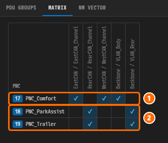
Figure 1-1. The MATRIX tab of the finished example. Rows are the three PNCs, columns are the physical channels. The PNC_Comfort row is marked for EastCAN, WestCAN and VLAN_Body; the PNC_ParkAssist and PNC_Trailer rows are marked for RearCAN and VLAN_Rear. These are the same values as the "Related buses" column of the table above. You see this screen again in Reviewing PDU GROUPS, MATRIX and NM VECTOR.
Why the PNC Identifiers Are 17, 18 and 19
A PNC identifier is not a label — it is a bit number inside the NM PDU. You therefore cannot use an arbitrary number: the identifier must fall within the space the PNC bit vector occupies in the NM PDU.
This example follows the standard CanNm layout.
| Position in the NM PDU | Content |
|---|---|
| Byte 0 | CBV (Control Bit Vector) |
| Byte 1 | NID (Node Identifier) |
| Byte 2 – Byte 7 | PNC bit vector |
The global configuration is therefore PNC VECTOR OFFSET 2 and PNC VECTOR LENGTH 6, and the usable identifiers run from bit 16 to bit 63. The calculation is as follows.
start bit = offset × 8       = 2 × 8       = 16
end   bit = (offset + length) × 8 − 1 = (2 + 6) × 8 − 1 = 63
AUTOSAR specifies this range in constr_3040. PAIO validation reports an identifier outside the range as an error.
Note. An early draft of this example used
8,9and10as the identifiers. They were lower than bit16, so they violatedconstr_3040, and the PAIO validation panel flagged them. That is why they moved to17,18and19. In PNC Definition and Connector PNC Properties you follow this same path, producing the error and then fixing it.
You check the actual values of PNC VECTOR OFFSET and PNC VECTOR LENGTH on the NM VECTOR tab in Reviewing PDU GROUPS, MATRIX and NM VECTOR.
The Five Layers a PNC Spans
PNC design does not end in a single editor because the AUTOSAR metamodel records a PNC across several elements. In PAIO, each layer has its own editor and its own model file.
| AUTOSAR element | Role | PAIO editor / file | Chapter |
|---|---|---|---|
PncMapping (SystemMapping) | PNC identifier, participating physical channels, I-PDU Group, VFC, service instances, wakeup frames | PNC dialog of the System editor / SYSTEM.io.model | Chapter 3, Chapter 7, Chapter 8 |
PNC properties of CommunicationConnector | pncGatewayType, wakeup CAN ID and mask, PNC filter array mask | Properties panel of the System editor / IVC.io.model | Chapter 3 |
ISignalIPduGroup | The communication unit a PNC switches on and off (Rx/Tx, container and leaf) | Signal editor and PNC dialog / SIGNAL.io.model | Chapter 4 |
PortGroup (= VFC) | The functional unit a PNC controls — a bundle of SWC ports | PortGroups of atomic SWCs in the VFB editor; member ports of compositions and adaptive applications in the SWC HIERARCHY of the PNC dialog / SWC/*.swc.io.model | Chapter 6, Chapter 7 |
NmNetworkHandle and NmHandleToFunctionGroupStateMapping | The channel through which the AP machine (HPC) requests and releases a PNC, plus the link to FunctionGroup states | Network Management on the MODULE tab of the Machine Configuration dialog in the VFB editor / Module/Machine/HPC.machine.io.model | Chapter 9, Chapter 10 |
CanNmCluster, UdpNmCluster | The PNC bit vector inside the NM PDU (offset and length), and the NM nodes | NM configuration of the System editor and the NM VECTOR tab of the PNC dialog | Chapter 3, Chapter 8 |
ServiceInstance (the SOME/IP provider and consumer) is not listed separately in this table. It is a value the PNC mapping references, and you create it in the Interface editor and the System editor in Chapter 5.
Note. The last two rows of the table both carry the name "NM", but they are different things.
NmNetworkHandleis the software channel through which the AP side requests a PNC, whereasCanNmClusterandUdpNmClusterdefine what the NM PDU actually looks like on the bus.
Check Your Work
- You can explain the name, identifier, trigger and related buses of each of the three PNCs from the table.
- You can show by calculation why the identifiers
17,18and19are valid and8,9and10are not. - You understand that PNC design is recorded across the System editor (including the PNC dialog), Signal, Interface, VFB and Machine Configuration.
Next Steps
In Topology Design you start from a PAIO window with no project open, create the project PNC, and draw the skeleton of the vehicle described in this chapter in the System editor.