Interfaces and SOME/IP Services
What You Will Do
In this chapter you create two kinds of interfaces in the Interface editor: the Sender-Receiver interfaces used by the CP ports between the end ECUs and the zones, and the service interfaces used for SOME/IP communication between the HPC and the zones. For each service interface you add a SOME/IP deployment (Service ID, version) and provider and consumer service instances. Finally, in the System editor you give each Ethernet connector an IP address and a UDP port (an application endpoint), and bind the service instances to the connectors.
You build SRI_ParkDistance and SVC_ParkDistance from scratch as the worked example, then repeat the same steps for the rest using the value tables.
When you finish this chapter, the model is in the following state.
- The SENDER-RECEIVER tab holds 11
SRI_*interfaces. - The SERVICE tab holds
SVC_ParkDistance,SVC_VehicleState, andSVC_ComfortControl, each with a SOME/IP deployment and service instances. - The five Ethernet connectors on the zone ECUs and the HPC have IP addresses and UDP application endpoints.
- All seven service instances are bound to Ethernet connectors, and no two instances on the same connector share a UDP port.
Before You Begin
- Finish Signals, PDUs, Frames, and I-PDU Groups.
- The topology in the System editor must contain the Ethernet connectors
HPC_Eth_Body_Conn,HPC_Eth_Rear_Conn,WestZone_Eth_Conn,EastZone_Eth_Conn, andSouthZone_Eth_Conn(you created them in Designing the Topology). - This chapter creates the following three services. You reuse the service names, Service IDs, and instance names verbatim later, in The PNC Dialog — Binding Per PNC.
| Service interface | Service ID | Provider | Consumer | Owning PNC |
|---|---|---|---|---|
SVC_ParkDistance (events DistanceUpdate, SensorFault / method SetSensitivity) | 0x1001 | SouthZone (ParkDistance_Provider) | HPC ParkAssistApp (ParkDistance_Consumer) | PNC_ParkAssist |
SVC_VehicleState (events GearPosition, TrailerAttached) | 0x1002 | HPC VehicleStateApp (VehicleState_Provider) | SouthZone (VehicleState_Consumer) | PNC_Trailer |
SVC_ComfortControl (event DoorStatus / methods LockAll, FoldMirrors) | 0x1003 | WestZone (ComfortControl_Provider_West, instance 1), EastZone (ComfortControl_Provider_East, instance 2) | HPC ComfortApp (ComfortControl_Consumer, ANY) | PNC_Comfort |
Creating the Sender-Receiver Interfaces
-
In the EDITOR view on the left, click Interface under DESIGN. The
PNC:Interfacetab opens. -
In the tab row at the top, click SENDER-RECEIVER. The INTERFACES list on the left shows "Add an interface", and CONFIGURATION in the middle shows "Select an interface".
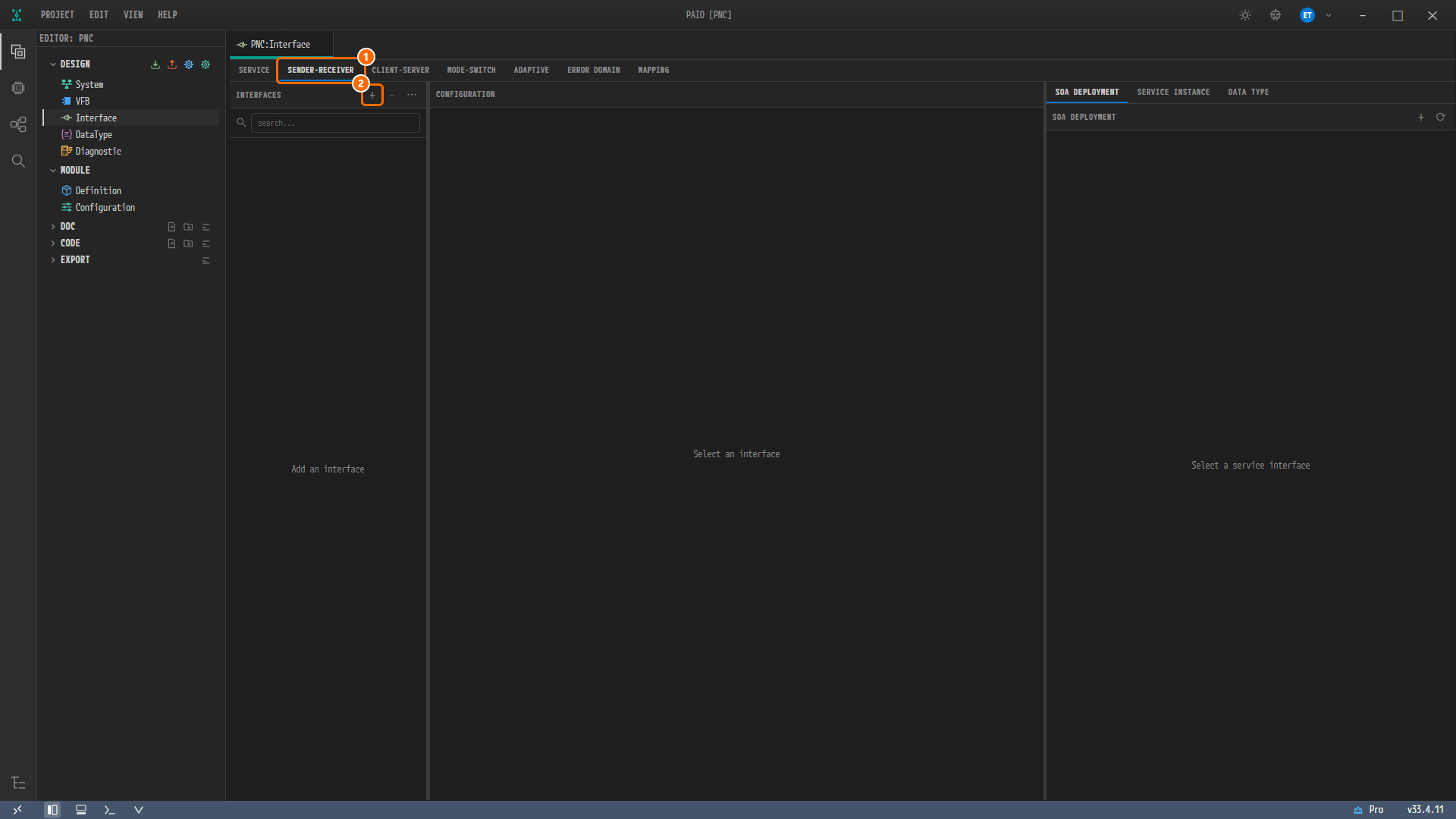
Figure 5-1. The Interface editor as first opened. The tabs along the top are SERVICE, SENDER-RECEIVER, CLIENT-SERVER, MODE-SWITCH, ADAPTIVE, ERROR DOMAIN, and MAPPING. ① the SENDER-RECEIVER tab, ② the + button to the right of the INTERFACES title.
-
Click the + button to the right of the INTERFACES title (tooltip Add Interface).
SenderReceiverInterface_0is added and immediately selected. -
Type
SRI_ParkDistancein NAME in the middle and pressEnter. The name in the list on the left changes at once.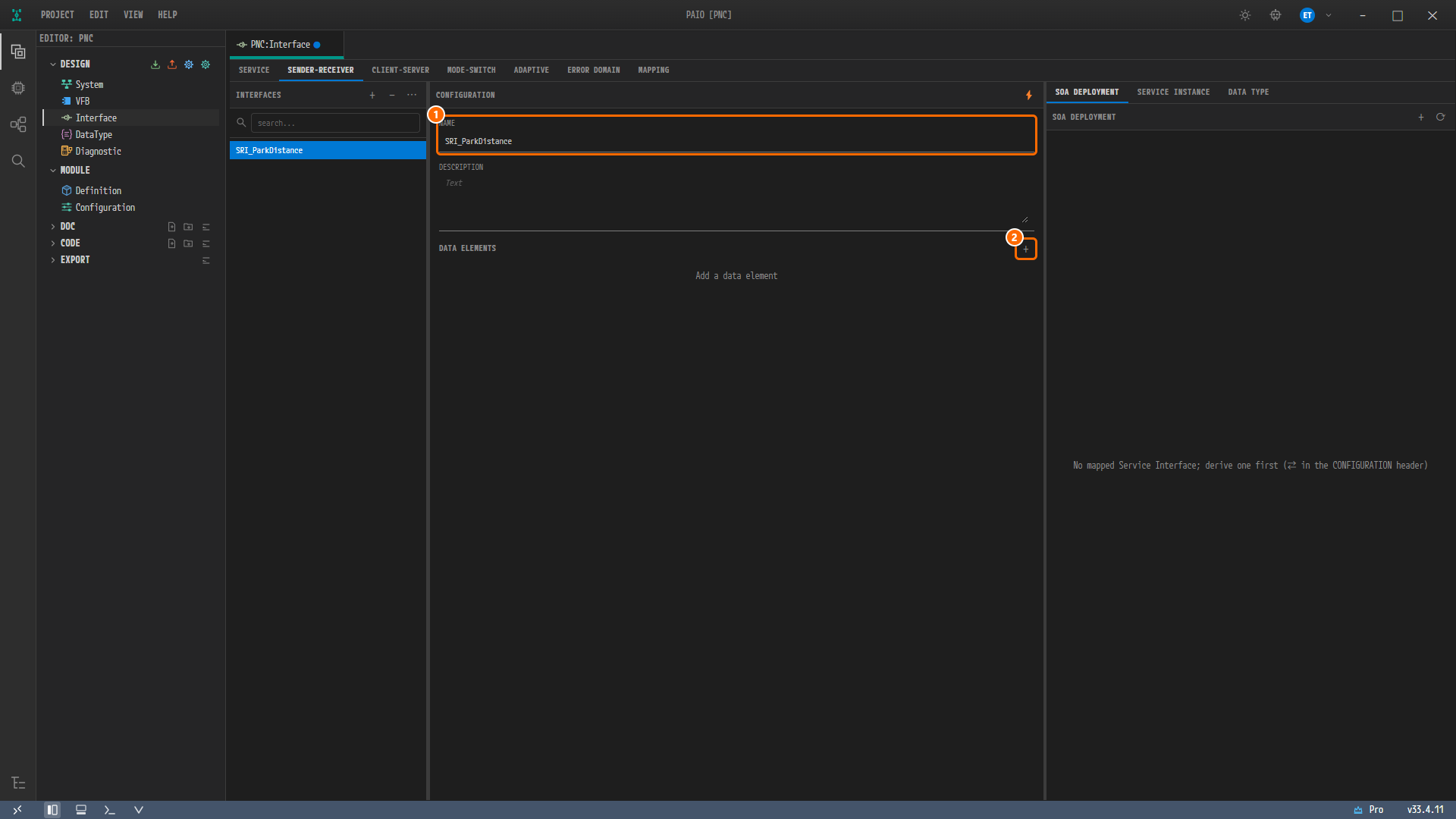
Figure 5-2. ① NAME =
SRI_ParkDistance. DATA ELEMENTS is still empty ("Add a data element"). ② Use the + button to the right of the DATA ELEMENTS title to add a data element. You can ignore the "No mapped Service Interface" notice in the right-hand panel in this chapter. -
Click the + button to the right of the DATA ELEMENTS title (tooltip Add Data Element). A
DataElement_0row is added with the default typeuint8, already expanded. -
In the expanded area, type
Distance1in NAME. -
Set the type. Click the TYPE field to open a "Type to search..." box and the type list. The list holds the built-in primitive types (
boolean,float32,float64,sint8…uint64).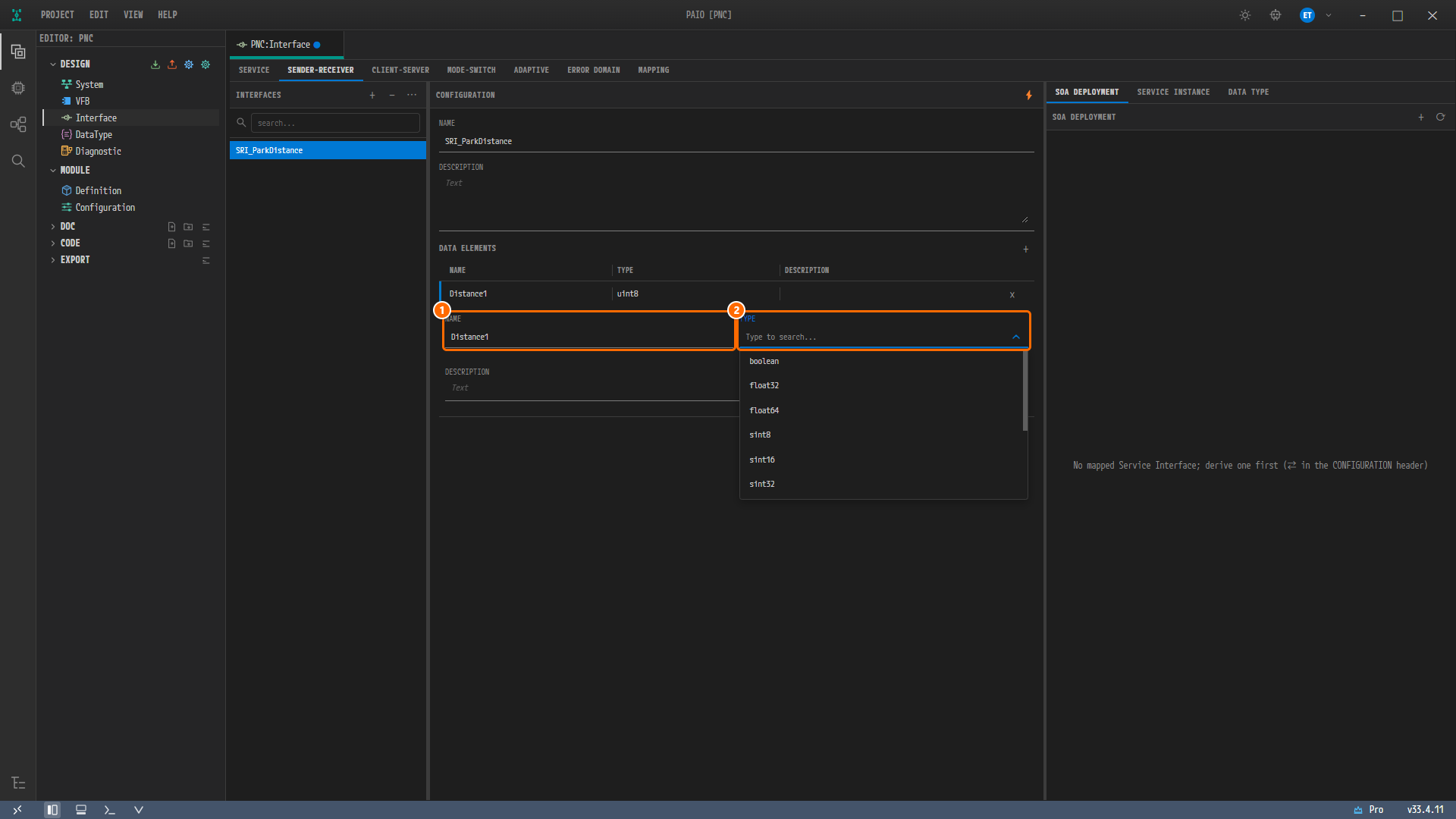
Figure 5-3. ① the data element NAME =
Distance1, ② the TYPE list. The screen shows only the top of the list. Scroll down or type in the search box to find the type you want. -
Select
uint8in the list.Distance1already hasuint8as its default type, so you can also just close the list and leave it as it is.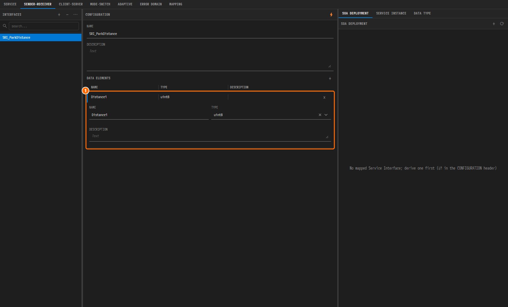
Figure 5-4. ① the data element
Distance1(TYPEuint8) after it is added. The row header shows a NAME, TYPE, and DESCRIPTION summary, and you edit the values in the expanded area. -
In the same way, click the + button in DATA ELEMENTS to add
Distance2,Distance3, andDistance4(uint8) andSensorFault(boolean). ForSensorFault, pickbooleanin the TYPE list.
The Remaining Sender-Receiver Interfaces
Create all of the following interfaces the same way. Every data element type is a built-in primitive.
| Interface | Data elements (type) |
|---|---|
SRI_DoorStatus | DoorOpen (boolean), LockState (uint8), WindowPos (uint8) |
SRI_SeatStatus | SeatPos (uint8), SeatHeat (uint8) |
SRI_ComfortCmd | LockCmd, WindowCmd, SeatMoveCmd, SeatHeatCmd (all uint8) |
SRI_MirrorStatus | FoldState, TiltX, TiltY (all uint8) |
SRI_MirrorCmd | FoldCmd, MoveCmd (all uint8) |
SRI_ParkDistance | Distance1, Distance2, Distance3, Distance4 (uint8), SensorFault (boolean) |
SRI_TrailerStatus | Attached (boolean), LampFault (uint8), BrakeLamp (boolean) |
SRI_TrailerCmd | LampCmd (uint8) |
SRI_WindowSwitch | Up, Down, Auto (all boolean) |
SRI_TailLamp | LampState (uint8) |
SRI_GearPosition | Gear (uint8) |
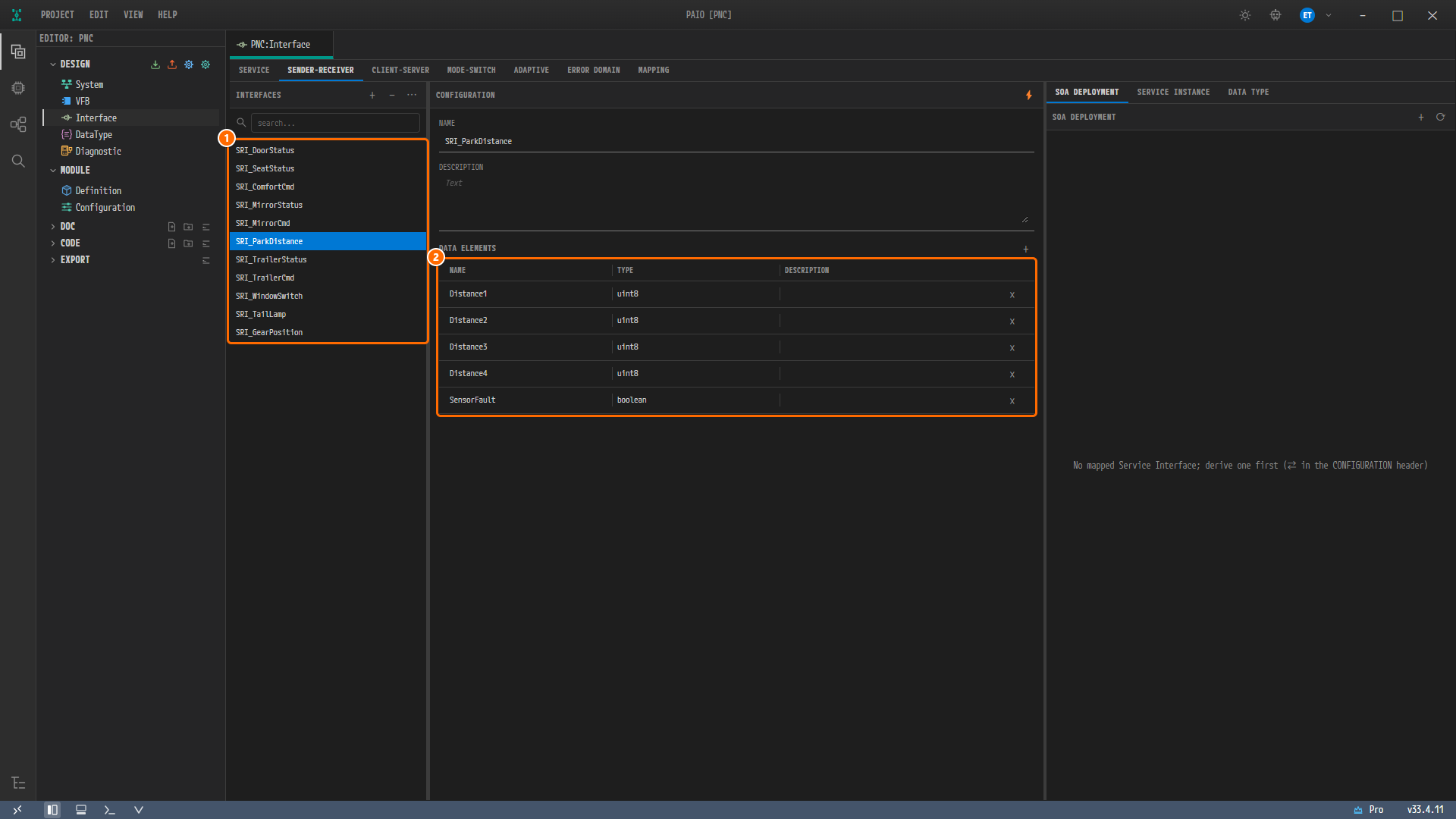
Figure 5-5. The SENDER-RECEIVER tab when finished. ① the 11 SRI_* entries in the INTERFACES list, ② the DATA ELEMENTS of SRI_ParkDistance: Distance1 through Distance4 (uint8) and SensorFault (boolean).
Creating the Service Interface
-
In the tab row at the top, click SERVICE.
-
Click the + button to the right of the INTERFACES title.
ServiceInterface_0is added and selected. -
Type
SVC_ParkDistancein NAME. -
Type
pnc::parkin C++ NAMESPACE and pressTab. -
Leave MAJOR VERSION
1and MINOR VERSION0at their default values.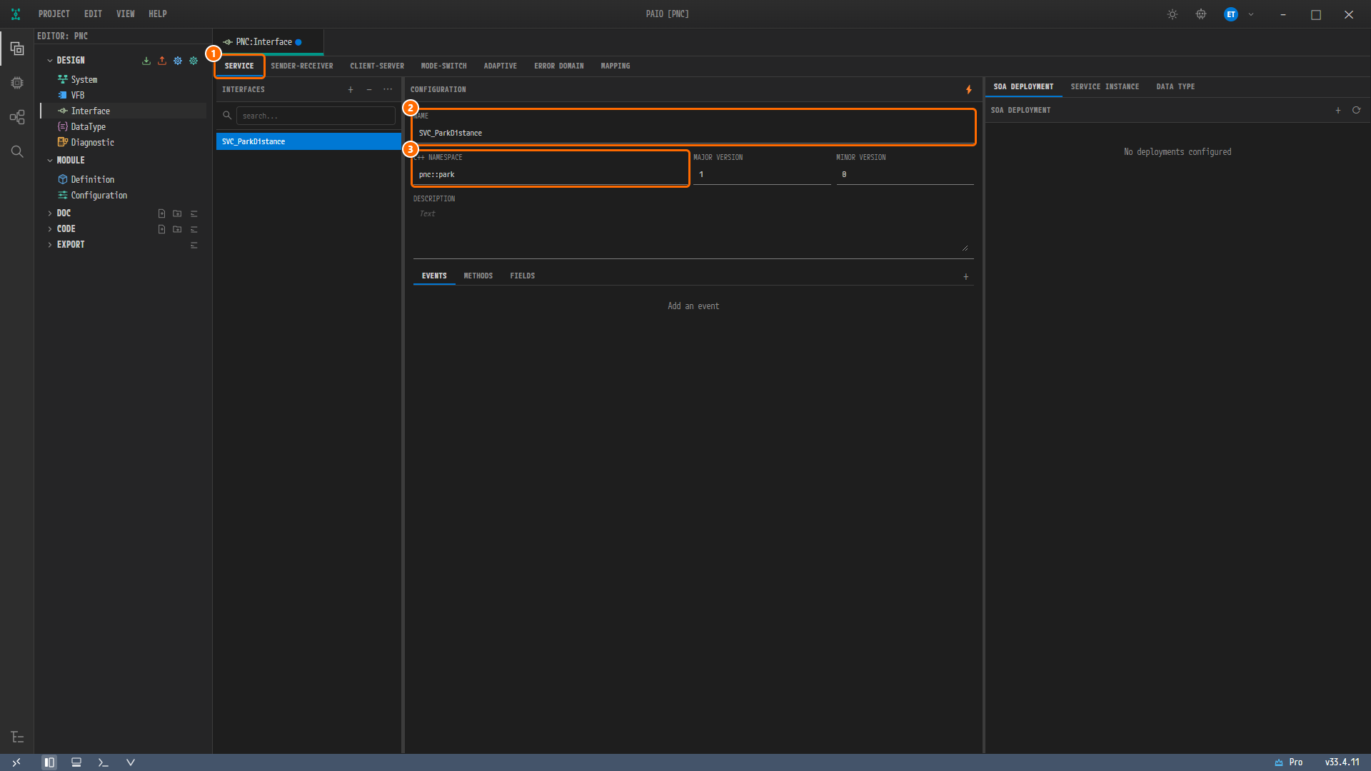
Figure 5-6. ① the SERVICE tab, ② NAME =
SVC_ParkDistance, ③ C++ NAMESPACE =pnc::park. Below are the EVENTS, METHODS, and FIELDS subtabs. SOA DEPLOYMENT on the right still shows "No deployments configured".
Adding Events
-
Click the EVENTS subtab.
-
Click the + button at the far right of the subtab row (tooltip Add Event). An
Event_0row is added with the default typeuint8. -
Type
DistanceUpdatein NAME. Leave the type asuint8. -
Click the + button again and type
SensorFaultin NAME. -
In the TYPE field of
SensorFault, selectboolean.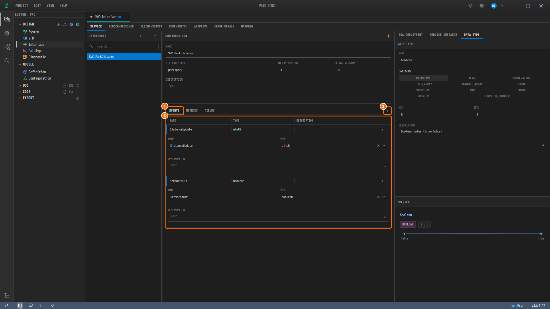
Figure 5-7. ① the EVENTS subtab, ② + (Add Event), ③ the events
DistanceUpdate(uint8) andSensorFault(boolean). As soon as you pick a type, the right-hand panel switches to the DATA TYPE subtab and shows the details ofboolean.
Note. When you pick a TYPE, the right-hand panel switches to the DATA TYPE subtab automatically. To add a deployment, click the SOA DEPLOYMENT subtab again.
Adding a Method
-
Click the METHODS subtab.
-
Click the + button at the far right of the subtab row (tooltip Add Method). A
Method_0row is added. -
Type
SetSensitivityin NAME. -
Leave METHOD TYPE at its default value, REQUEST AND RESPONSE. The ACCESS badge in the row header reads
R&R.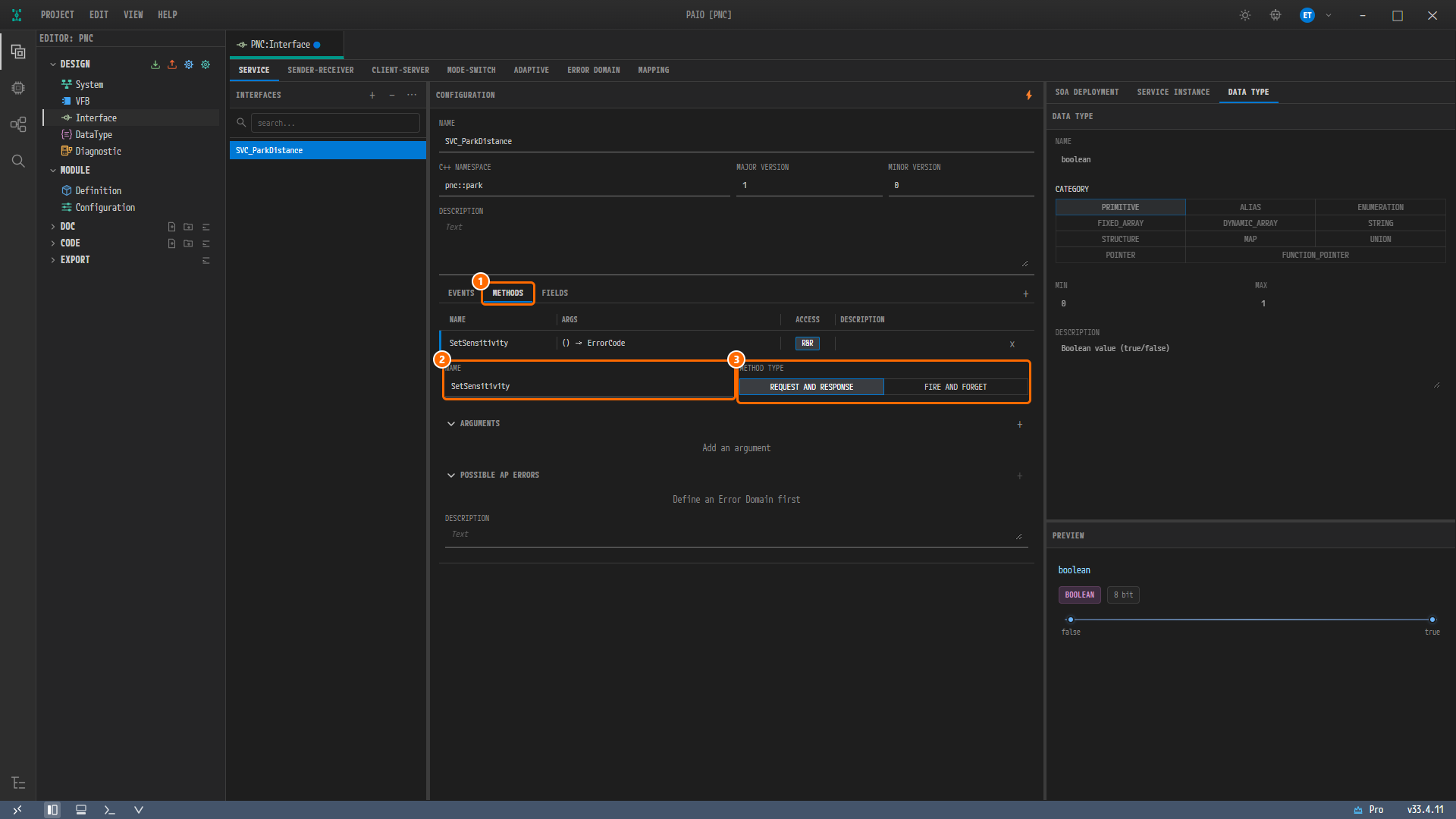
Figure 5-8. ① the METHODS subtab, ② NAME =
SetSensitivity, ③ METHOD TYPE = REQUEST AND RESPONSE. For a method with no response, select FIRE AND FORGET. This example does not use ARGUMENTS or POSSIBLE AP ERRORS.
Adding the SOME/IP Deployment
A deployment is built from the events and methods that exist at the moment you add it. Add the deployment only after you have defined all events and methods.
-
In the right-hand panel, click the SOA DEPLOYMENT subtab.
-
Click the + button to the right of the SOA DEPLOYMENT title (tooltip Add Deployment). A menu with SOME/IP, DDS, and IPC opens.

Figure 5-9. ① + (Add Deployment), ② the protocol menu. Select SOME/IP.
-
Select SOME/IP. A deployment card, SOME/IP
SVC_ParkDistance, appears collapsed. -
Click the card header to expand it. If the right-hand panel switches to DATA TYPE, click SOA DEPLOYMENT again.
-
To the right of the SERVICE ID label, click HEX in the DEC | HEX toggle.
-
Type
1001in SERVICE ID and pressTab. The value appears as0x1001. -
Confirm MAJOR VERSION
1and MINOR VERSION0.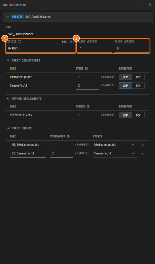
Figure 5-10. The expanded deployment card. ① SERVICE ID =
0x1001(HEX mode), ② MAJOR VERSION1, MINOR VERSION0. EVENT DEPLOYMENTS (DistanceUpdate1,SensorFault2) and METHOD DEPLOYMENTS (SetSensitivity1) are filled in automatically, and the transport is UDP throughout. EVENT GROUPS gets one group per event (EG_DistanceUpdate,EG_SensorFault). -
As in the finished example, merge the two events into a single group,
EG_SVC_ParkDistance(EVENTGROUP ID1) (Figure 5-16).- In EVENT GROUPS, click the x at the right of the
EG_SensorFaultrow to delete it. - Change the NAME of the remaining
EG_DistanceUpdaterow toEG_SVC_ParkDistance. Leave EVENTGROUP ID at1. - Click the EVENTS field in the same row and also check
SensorFaultin the list that opens. EVENTS should then readDistanceUpdate, SensorFault.
- In EVENT GROUPS, click the x at the right of the
Adding Provider and Consumer Instances
-
Hover over the deployment card header. A small + button appears at the right of the header (tooltip Add service instance). This button is visible only while you hover.
-
Click the + button and select Provider.
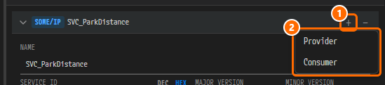
Figure 5-11. ① the + (Add service instance) in the card header, ② the Provider / Consumer menu.
-
Click the + button again and select Consumer.
-
Click the card header to collapse it. The summary shows the instances you just added, under their default names.
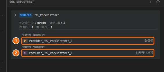
Figure 5-12. The collapsed deployment card summary (SERVICE ID =
0x1001, VERSION1.0, EVENTS = 2, METHODS = 1). ①Provider_SVC_ParkDistance_1(0x0001) under SERVICE PROVIDERS, ②Consumer_SVC_ParkDistance_1(0xFFFF (ANY)) under SERVICE CONSUMERS. -
Click the provider row under SERVICE PROVIDERS. The right-hand panel switches to the SERVICE INSTANCE subtab and the provider card expands.
-
Change NAME to
ParkDistance_Provider. -
Type
1in INSTANCE ID and pressTab.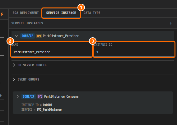
Figure 5-13. ① the SERVICE INSTANCE subtab, ② NAME =
ParkDistance_Provider, ③ INSTANCE ID =1. Leave SD SERVER CONFIG and EVENT GROUPS collapsed. -
Click the provider card header to collapse it, then click the consumer card header ([C]
Consumer_SVC_ParkDistance_1) to expand it. -
Change NAME to
ParkDistance_Consumer. -
Type
1in REQUIRED INSTANCE ID.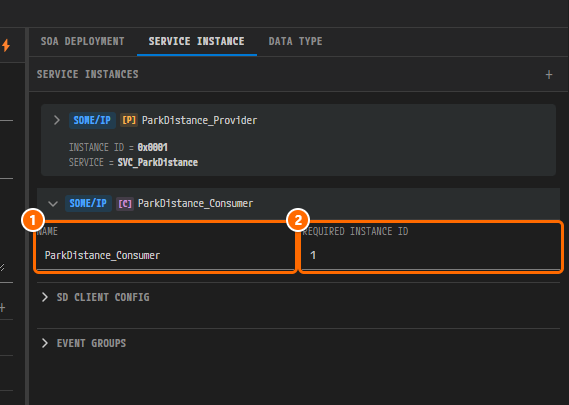
Figure 5-14. ① NAME =
ParkDistance_Consumer, ② REQUIRED INSTANCE ID =1. The provider card above is collapsed and shows only its summary (INSTANCE ID =0x0001, SERVICE =SVC_ParkDistance). -
Press
Ctrl+Sto save. The ● marker on thePNC:Interfacetab disappears.
Note. The default REQUIRED INSTANCE ID of a consumer,
0xFFFF (ANY), means "find any instance". In this example,ComfortControl_Consumerkeeps this default value.
Caution. When you add a SOME/IP deployment, PAIO generates the following data automatically. The finished example does not contain it.
SVC_ParkDistance_SRin the SENDER-RECEIVER list- Four PDUs in the Signal editor (
SVC_ParkDistance_DistanceUpdate_PDU,SVC_ParkDistance_SensorFault_PDU,SVC_ParkDistance_SetSensitivity_Call_PDU,SVC_ParkDistance_SetSensitivity_Return_PDU)These PDUs raise no validation error.
The Remaining Service Interfaces and Instances
Create SVC_VehicleState and SVC_ComfortControl the same way, and add their deployments and instances. Every version is 1.0 and every transport is UDP. For EVENT GROUPS, consolidate the groups generated per event into the single group given in the table. SVC_ComfortControl has only one event, so just change the NAME of its automatically generated group to EG_SVC_ComfortControl.
| Service | C++ NAMESPACE | Events (type, EVENT ID) | Methods (METHOD ID, METHOD TYPE) | SERVICE ID | Event group (EVENTGROUP ID) |
|---|---|---|---|---|---|
SVC_ParkDistance | pnc::park | DistanceUpdate (uint8, 1), SensorFault (boolean, 2) | SetSensitivity (1, REQUEST AND RESPONSE) | 0x1001 (4097) | EG_SVC_ParkDistance (1): both events |
SVC_VehicleState | pnc::vehicle | GearPosition (uint8, 1), TrailerAttached (boolean, 2) | none | 0x1002 (4098) | EG_SVC_VehicleState (1): both events |
SVC_ComfortControl | pnc::comfort | DoorStatus (uint8, 1) | LockAll (1, REQUEST AND RESPONSE), FoldMirrors (2, FIRE AND FORGET) | 0x1003 (4099) | EG_SVC_ComfortControl (1): DoorStatus |
| Instance | Role | Deployment | INSTANCE ID / REQUIRED INSTANCE ID |
|---|---|---|---|
ParkDistance_Provider | Provider | SVC_ParkDistance | 1 (0x0001) |
ParkDistance_Consumer | Consumer | SVC_ParkDistance | 1 |
VehicleState_Provider | Provider | SVC_VehicleState | 1 (0x0001) |
VehicleState_Consumer | Consumer | SVC_VehicleState | 1 |
ComfortControl_Provider_West | Provider | SVC_ComfortControl | 1 (0x0001) |
ComfortControl_Provider_East | Provider | SVC_ComfortControl | 2 (0x0002) |
ComfortControl_Consumer | Consumer | SVC_ComfortControl | default 0xFFFF (ANY) |
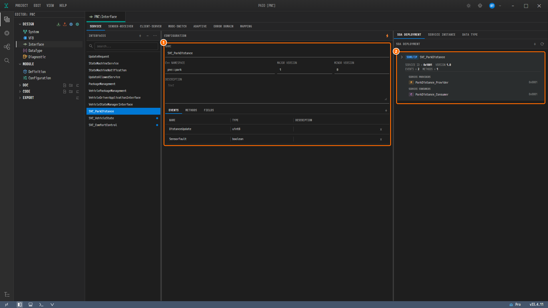
Figure 5-15. The SERVICE tab when finished. ① the NAME, C++ NAMESPACE, version, and two events of SVC_ParkDistance. ② the collapsed SOME/IP deployment card summary: 0x1001, 1.0, provider ParkDistance_Provider, consumer ParkDistance_Consumer. The blue dot to the right of a service name in the list marks a service that has a SOME/IP deployment. The other services in the list, such as UpdateRequest, are added in Importing the PARA Platform and the PNC Request Ports; you do not create them in this chapter.
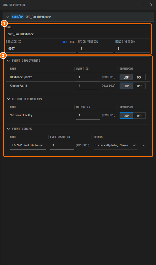
Figure 5-16. The deployment card of the finished example, expanded. ① NAME, SERVICE ID, and version. Here the card is in DEC mode, so the ID reads 4097; click HEX and it reads 0x1001. ② EVENT DEPLOYMENTS, METHOD DEPLOYMENTS, and EVENT GROUPS. Both events are bundled into the single event group EG_SVC_ParkDistance.
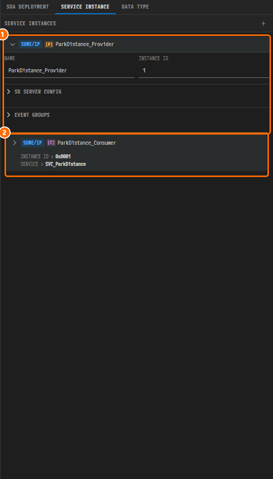
Figure 5-17. The SERVICE INSTANCE subtab of the finished example. ① ParkDistance_Provider (INSTANCE ID 1), ② the collapsed ParkDistance_Consumer card summary.
Note. The default SD (Service Discovery) settings of a newly created instance differ from the values in the finished example. The SD settings live under SD SERVER CONFIG on a provider card and SD CLIENT CONFIG on a consumer card. The values used in the finished example, named after the model fields, are the following.
SD setting Provider example value Consumer example value initial-delay min / max 0 / 0.01 0 / 0.01 repetition-base-delay 0.15 0.02 repetition-max 2 5 offer-cyclic-delay 3 — ttl 10 10
Giving the Connectors IP Addresses and Application Endpoints
A service instance communicates over the IP address and UDP port of the connector it is bound to. So before you bind anything, give every Ethernet connector an IP address and the UDP ports (application endpoints) that its instances will use. HPC_Eth_Rear_Conn is the worked example.
-
In the EDITOR view on the left, click System under DESIGN to open the System editor (tab
PNC:System). -
Click the Ethernet connector
HPC_Eth_Rear_Conn, at the right of the lower edge of theHPCnode (see ① in Figure 5-22). The properties panel title changes to ETHERNET CONNECTOR. Confirm that NAME isHPC_Eth_Rear_Connand CONNECTED CHANNEL isBackbone / VLAN_Rear (VLAN: 200). -
If the NETWORK ENDPOINT section is collapsed, click its header to expand it. Leave the IPv4 | IPv6 toggle at the right of the header on IPv4.
-
Type
192.168.200.1in UNICAST IPV4 ADDRESS and255.255.255.0in NETWORK MASK. For ADDRESS SOURCE, select FIXED.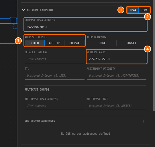
Figure 5-18. The NETWORK ENDPOINT section of
HPC_Eth_Rear_Conn. ① the IPv4 | IPv6 toggle at the right of the header — IPv4 is selected. ② UNICAST IPV4 ADDRESS =192.168.200.1. ③ ADDRESS SOURCE = FIXED (AUTO-IP and DHCPv4 are also available). ④ NETWORK MASK =255.255.255.0. This example leaves DEFAULT GATEWAY, KEEP BEHAVIOR, TTL, ASSIGNMENT PRIORITY, MULTICAST CONFIG, and DNS SERVER ADDRESSES empty. -
Click the + button in the APPLICATION ENDPOINTS header (tooltip Add Application Endpoint). One endpoint row is added. A new row is TCP by default.
-
Click the new row to expand it, change TYPE to UDP, and type
30501in PORT NUMBER. The row summary changes to UDPHPC_Eth_Rear_Conn, 192.168.200.1:30501.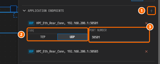
Figure 5-19. The APPLICATION ENDPOINTS section. ① the + button to the right of the title (tooltip Add Application Endpoint). ② the TYPE of the expanded endpoint — select UDP in the TCP | UDP toggle. ③ PORT NUMBER =
30501. The card header shows the summary UDPHPC_Eth_Rear_Conn, 192.168.200.1:30501. The collapsed card below it is the30503endpoint you add in step 7. -
Repeat steps 5 and 6 to add one more endpoint, UDP
30503.
Fill in the remaining Ethernet connectors the same way. NETWORK MASK is 255.255.255.0 for all of them, and ADDRESS SOURCE is FIXED for all of them.
| Node / connector | UNICAST IPV4 ADDRESS | UDP application endpoint (PORT NUMBER) |
|---|---|---|
HPC / HPC_Eth_Body_Conn | 192.168.100.1 | 30501 |
HPC / HPC_Eth_Rear_Conn | 192.168.200.1 | 30501, 30503 |
WestZone / WestZone_Eth_Conn | 192.168.100.11 | 30502 |
EastZone / EastZone_Eth_Conn | 192.168.100.13 | 30502 |
SouthZone / SouthZone_Eth_Conn | 192.168.200.12 | 30502, 30503 |
Note. PAIO names endpoints automatically, in the form
<node>_<connector>_UDP_<port>. The names may differ from those in the finished example (HPC_Rear_UDP_30501and so on). The30503entries in bold are the ports the consumer side uses where two instances are bound to the same connector.
Binding Service Instances to the Connectors
Now bind the service instances to the connectors. Once bound, an instance uses the IP address and port of that connector.
-
With
HPC_Eth_Rear_Connstill selected, click the + button in the SERVICE INSTANCES section header (tooltip Add Service Instance). The Select Service Instance dialog opens. -
Select the check box in the
ParkDistance_Consumerrow and click Bind.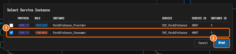
Figure 5-20. The Select Service Instance dialog. The columns are PROTOCOL, ROLE, INSTANCE, SERVICE, SERVICE ID, and INSTANCE ID. ① the
ParkDistance_Consumerrow checked, ② Bind. SERVICE ID appears in decimal (4097). -
A SOME/IP C
ParkDistance_Consumercard appears under SERVICE INSTANCES. It has no port yet. Click the card to expand it and you see IP ADDRESS (192.168.200.1, not editable because it is the connector address), TCP PORT, and UDP PORT. The TLS (TCP) and TLS (UDP) rows below them stay empty in this example. -
Click the ▾ button to the right of UDP PORT. The list of application endpoint ports on this connector (
30501,30503) opens. -
Select
30503.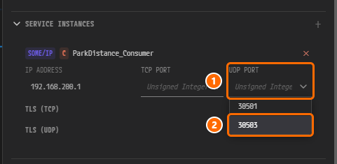
Figure 5-21. ① the UDP PORT list, ②
30503.VehicleState_Provideron the same connector uses30501, so the consumer gets30503, which does not collide. -
Click another element on the canvas, then click
HPC_Eth_Rear_Connagain. The card summary line refreshes toUDP:30503.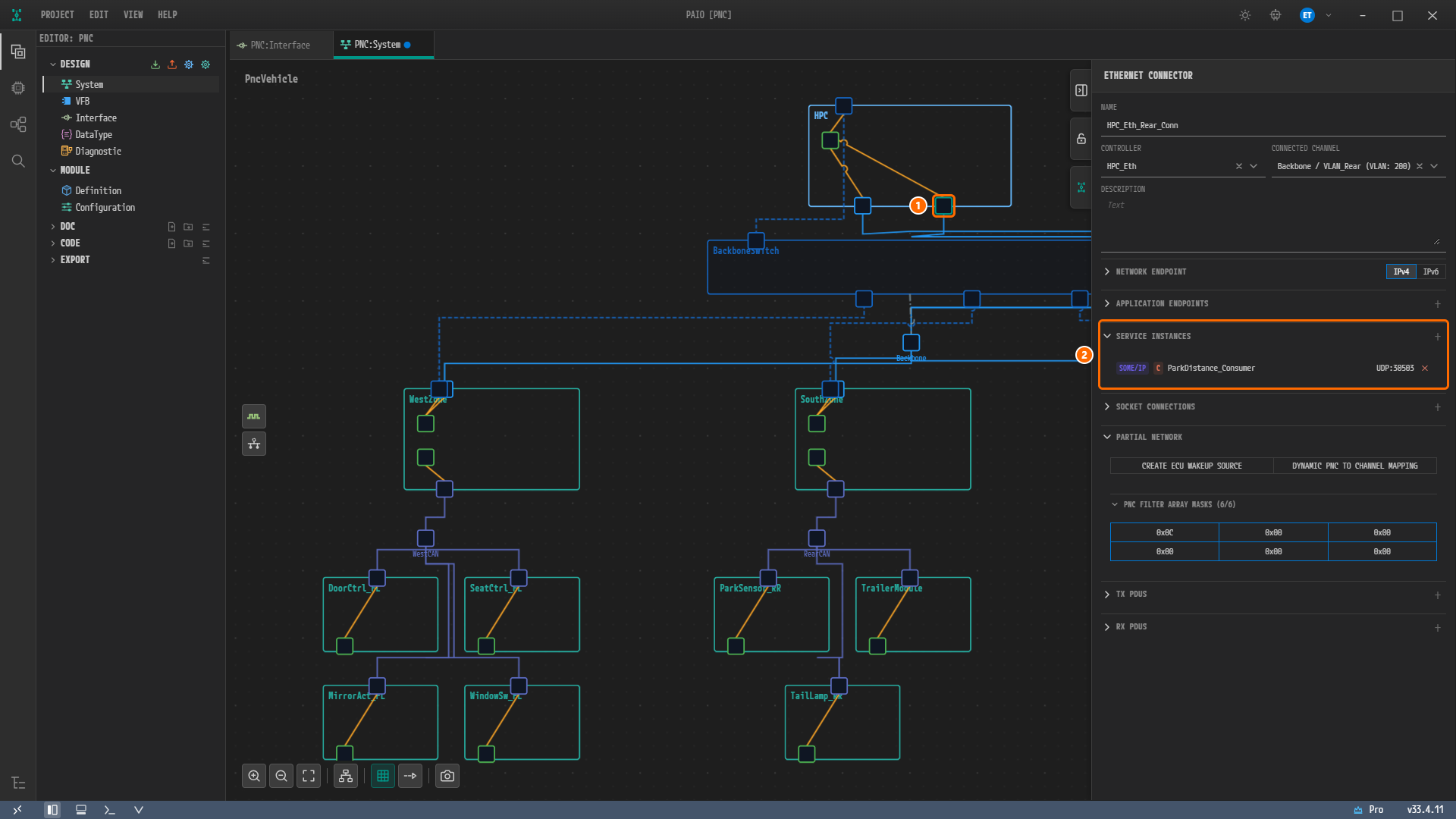
Figure 5-22. ① the selected connector
HPC_Eth_Rear_Conn, ② the SERVICE INSTANCES summary line SOME/IP CParkDistance_ConsumerUDP:30503.VehicleState_Provideris not bound yet, so only one line appears. The ● marker on the tab means there are unsaved changes. -
Press
Ctrl+Sto save.
Note. When you change a port, the card summary line (
UDP:…) does not update right away. The model takes the change immediately, and the summary refreshes when you select the connector again.
Note. From Bind until the UDP port is set, the validation icon (V) in the status bar carries a red badge
1, and the VALIDATION panel lists one error forParkDistance_Consumer:Service "SVC_ParkDistance" uses UDP, but the mapping of "ParkDistance_Consumer" on "HPC/HPC_Eth_Rear_Conn" defines no UDP port.Once the port is set in step 5, the error is gone and the badge disappears (Figure 5-22). The tooltip of the icon keeps the last count,Validation: 1 error(s), 0 warning(s), 0 info(s); the VALIDATION panel shows the current result.
The Remaining Bindings
Bind all seven instances the same way. The ports in bold are set to 30503 so that they do not collide with the other instance on the same connector.
| Node / connector | Instances to bind (role, UDP PORT) |
|---|---|
HPC / HPC_Eth_Body_Conn | ComfortControl_Consumer (C, 30501) |
HPC / HPC_Eth_Rear_Conn | VehicleState_Provider (P, 30501), ParkDistance_Consumer (C, 30503) |
WestZone / WestZone_Eth_Conn | ComfortControl_Provider_West (P, 30502) |
EastZone / EastZone_Eth_Conn | ComfortControl_Provider_East (P, 30502) |
SouthZone / SouthZone_Eth_Conn | ParkDistance_Provider (P, 30502), VehicleState_Consumer (C, 30503) |
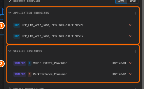
Figure 5-23. HPC_Eth_Rear_Conn when finished. ① the two UDP endpoints under APPLICATION ENDPOINTS (HPC_Eth_Rear_Conn, 192.168.200.1:30501, HPC_Eth_Rear_Conn, 192.168.200.1:30503). ② under SERVICE INSTANCES, P VehicleState_Provider UDP:30501 and C ParkDistance_Consumer UDP:30503.
Caution. Binding two instances to the same IP address and the same UDP port raises a validation error (
paio_someip_address_port_unique). When a connector carries more than one instance, give each one a different port.
Why Does a PNC Reference Service Instances?
The HPC (AP) and the zone ECUs (CP) communicate over SOME/IP. A PNC can reference service instances as well as I-PDU groups and physical channels. Referencing a service instance records in the model which services require that PNC to be awake. For example, when PNC_ParkAssist sleeps, SVC_ParkDistance becomes unavailable too.
For this reference to mean anything, the instance must be bound to a connector. Only with a binding does export produce the mapping that ties the instance to a machine (SomeipServiceInstanceToMachineMapping). That is why the instance names you set in this chapter are used both in the connector bindings and in SERVICE INSTANCES in The PNC Dialog — Binding Per PNC.
Check Your Work
- The SENDER-RECEIVER tab holds 11
SRI_*interfaces, andSRI_ParkDistancehas five data elements. - The SERVICE tab holds
SVC_ParkDistance,SVC_VehicleState, andSVC_ComfortControl. - The SOA DEPLOYMENT card summary of each service shows Service ID
0x1001,0x1002, or0x1003and version1.0. - The SERVICE INSTANCE subtab holds four providers and three consumers, under the names given in the table.
- In the System editor, the five Ethernet connectors have the UNICAST IPV4 ADDRESS values and the UDP application endpoints from the table.
- In the System editor, selecting
HPC_Eth_Rear_ConnshowsVehicleState_ProviderUDP:30501andParkDistance_ConsumerUDP:30503under SERVICE INSTANCES. - Neither the Interface editor tab nor the System editor tab shows the unsaved-changes marker (●).
Next Steps
In VFB and VFC (PortGroup) you group the SWC ports that take part in a function into PortGroups to form VFCs (Virtual Function Clusters).