PNC Catalog, Connector PNC Attributes, and NM Configuration
What You Will Do
In this chapter you define the three PNCs (Partial Network Clusters) the example uses, in the PNC dialog. You deliberately save the first one with an invalid identifier so that you see the validation panel report the error and work through fixing it. Next you check where the PNC bit vector sits inside the NM PDU, enter the PNC gateway role, the wakeup condition, and the filter mask on each connector, and specify which PNCs pass through each backbone switch port. Finally you fill in the values of the NM clusters and NM nodes that carry the PNC bit vector.
When you finish this chapter, you have the following:
- The PARTIAL NETWORKS list in the PNC dialog contains
PNC_Comfort(17),PNC_ParkAssist(18), andPNC_Trailer(19). - On the NM VECTOR tab, PNC VECTOR OFFSET is
2and PNC VECTOR LENGTH is6. - The PARTIAL NETWORK section of every connector has a gateway type and a filter mask.
- The PARTIAL NETWORK section of the ECU nodes and the
HPCnode has timer values. - The four ports of
BackboneSwitchhave PNC MAPPINGS. - The NM clusters have NM PNC PARTICIPATION and NM timing values, and the NM nodes have an NM NODE ID. You fill in the NM-PDU references of the NM nodes after you create the NM-PDUs in Signals, PDUs, Frames, and I-PDU Groups and come back to this chapter.
Before You Begin
- Finish Topology Design so that all nodes, clusters, connectors, and switch ports exist.
- In the EDITOR view on the left, click System under DESIGN to open the System editor (tab PNC:System), and leave it open.
- The NM Configuration section at the end of this chapter has one exception. TX-NM-PDU-REFS and RX-NM-PDU-REFS on an NM node are fields where you pick from the 18 NM-PDUs created in Signals, PDUs, Frames, and I-PDU Groups, so the candidate list is still empty now. Do only that step after you finish Chapter 4, then come back to this section. Enter all the other NM values now.
This chapter defines the following PNCs.
| PNC IDENTIFIER | NAME | Position in the filter mask |
|---|---|---|
17 | PNC_Comfort | Byte 0, bit 1 → 0x02 |
18 | PNC_ParkAssist | Byte 0, bit 2 → 0x04 |
19 | PNC_Trailer | Byte 0, bit 3 → 0x08 |
Note. The screenshots in this chapter come from the tutorial example project, so the root name at the top left of the canvas appears as
PncVehicle. In your own project it may well appear asSystem.
Opening the PNC Dialog
-
In the vertical icon strip along the left edge of the System editor canvas, click the second (lower) icon, Partial Network (PNC). The upper icon, Signal, opens the Signal editor.
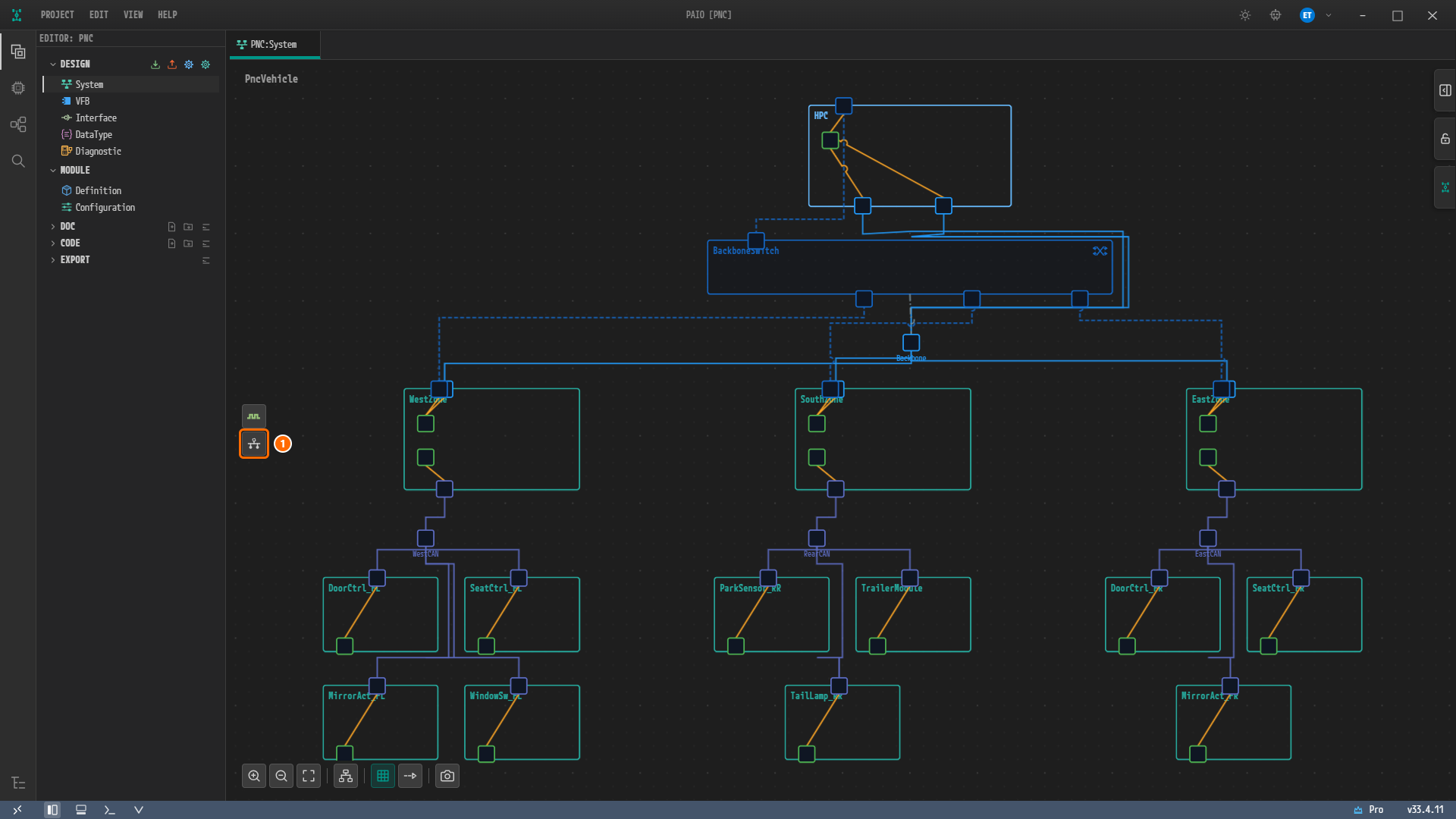
Figure 3-1. The System editor. ① The second (lower) icon in the vertical icon strip along the left edge of the canvas is the PNC button. The icon above it is Signal.
Hover over it and the Partial Network (PNC) tooltip appears.

Figure 3-2. ① Hovering over the PNC button. The Partial Network (PNC) tooltip appears to the right of the button.
-
The Partial Network (PNC) Configuration dialog opens. At first the PARTIAL NETWORKS list on the left is empty, and the center shows "No PNC mapping yet. Click [+] to declare a Partial Network Cluster." On the right are the PDU GROUPS, MATRIX, and NM VECTOR tabs.
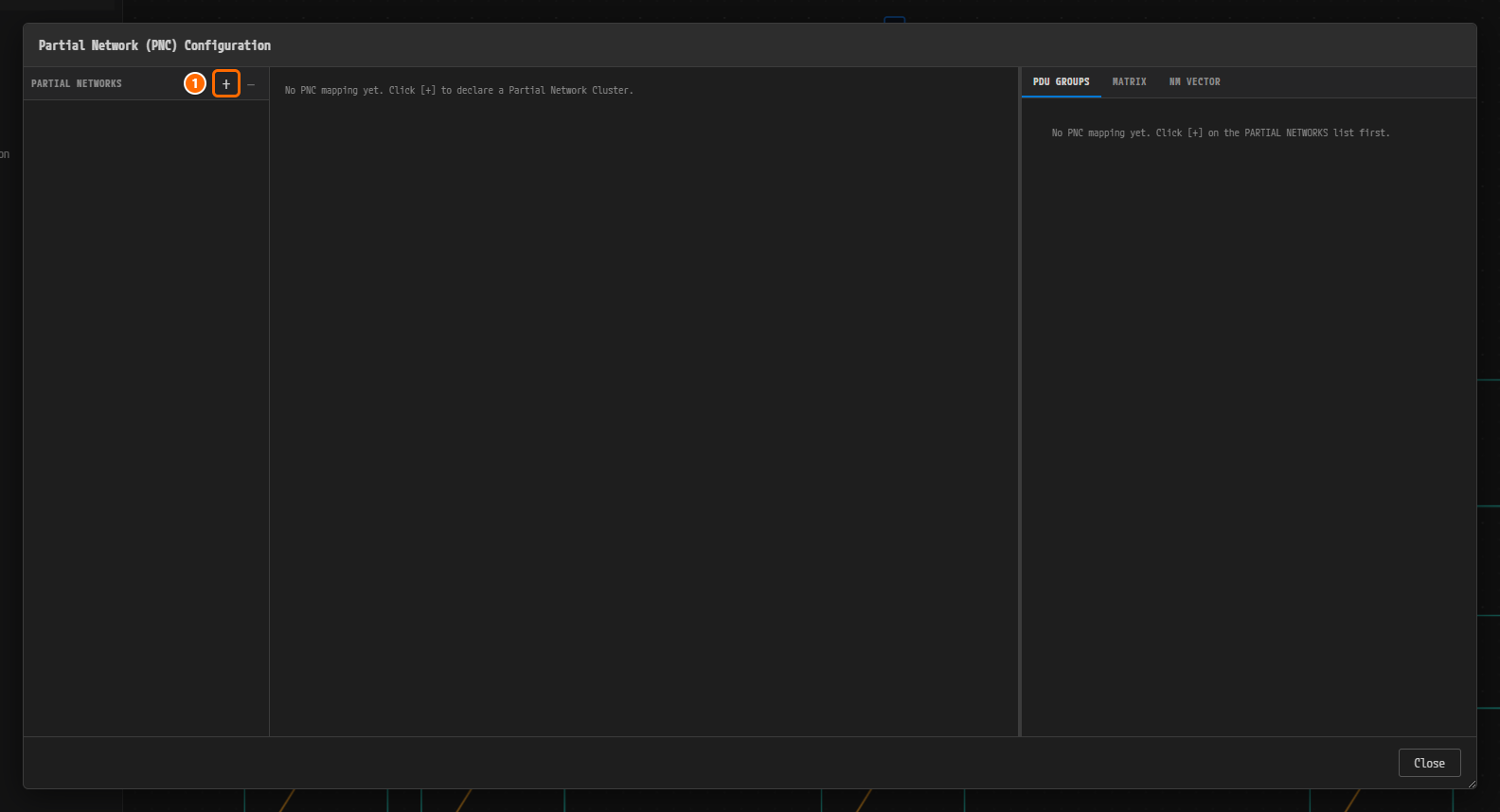
Figure 3-3. The PNC dialog as first opened. ① The [+] button to the right of the PARTIAL NETWORKS header adds a PNC. Close at the bottom right closes the dialog.
Adding the First PNC
-
Click the [+] button to the right of the PARTIAL NETWORKS header (tooltip Add PNC Mapping).
-
A PNC 0 Pnc_0 entry appears in the list and is selected. The PARTIAL NETWORK CLUSTER section in the center shows PNC IDENTIFIER
0and NAMEPnc_0. The identifier is assigned automatically as the lowest number not yet in use. The ● marker in front of the dialog title means there are unsaved changes.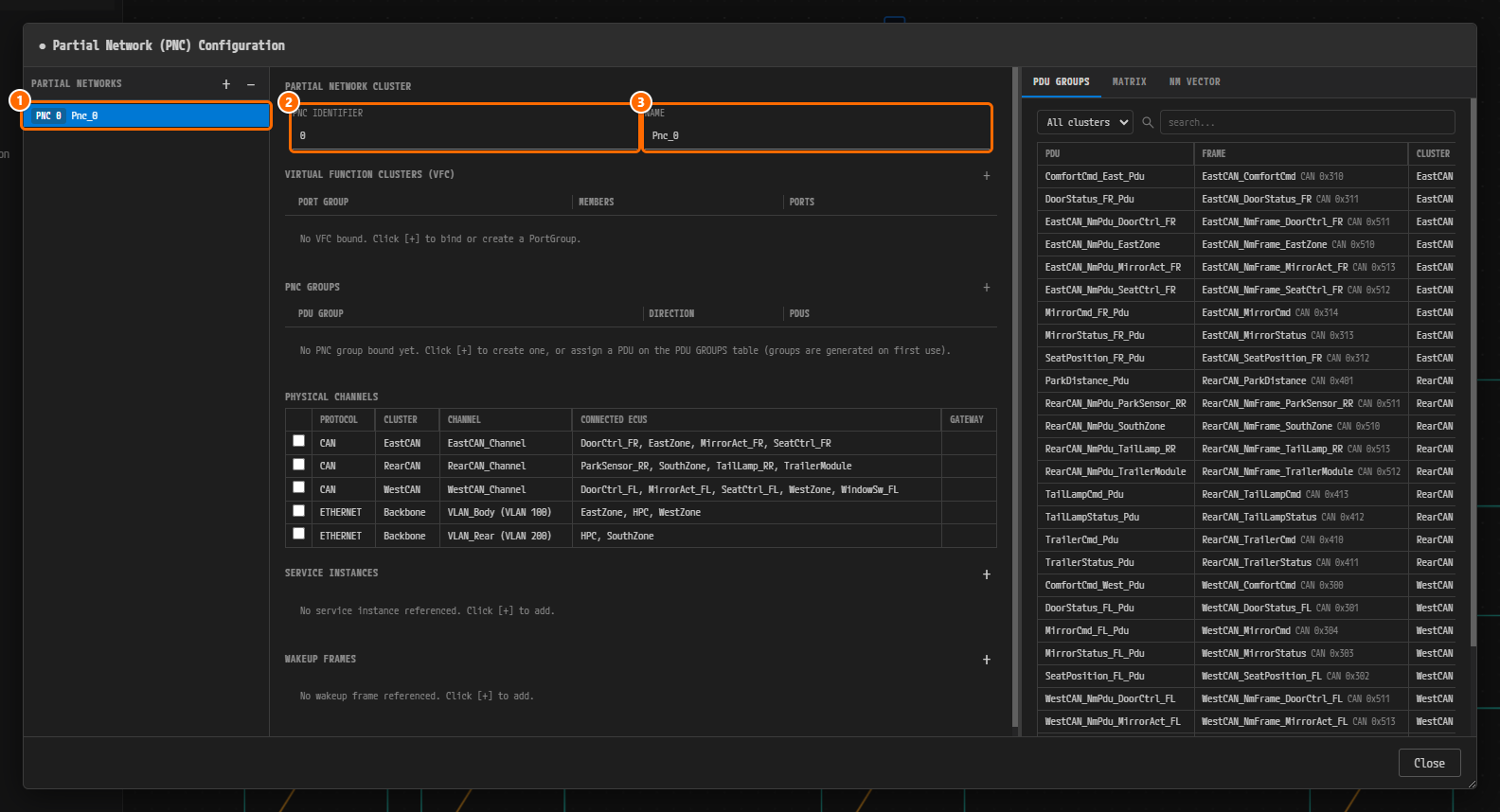
Figure 3-4. Right after clicking [+]. ① The new list entry PNC 0 Pnc_0, ② PNC IDENTIFIER =
0, ③ NAME =Pnc_0. You fill in VIRTUAL FUNCTION CLUSTERS (VFC), PNC GROUPS, PHYSICAL CHANNELS, SERVICE INSTANCES, and WAKEUP FRAMES at the bottom of the center area in PNC Dialog — Per-PNC Bindings.Note. After you click [+], the "Add PNC Mapping" tooltip sometimes stays on screen above the dialog title bar. This is only a leftover display and does not affect input.
-
Type
PNC_Comfortin NAME and pressEnter. The list entry changes to PNC 0 PNC_Comfort.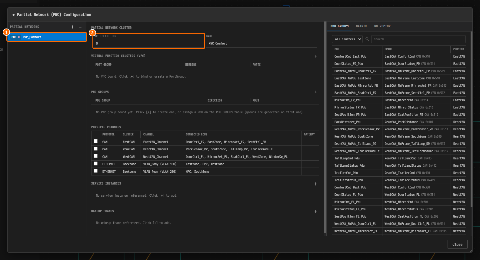
Figure 3-5. ① The list entry changes to PNC 0 PNC_Comfort. ② This time leave PNC IDENTIFIER at
0on purpose. -
Press
Ctrl+Sto save. The ● marker in front of the title disappears. -
Click Close to close the dialog.
Note. If you click Close without saving, a "Do you want to save the changes?" confirmation window appears. Save saves and then closes; Don't Save discards the changes and closes.
Note. What you save in the PNC dialog is written to the SYSTEM model (
SYSTEM.io.model). The System editor tab does not change.
Checking and Fixing the Validation Error
Because you saved with the identifier left at 0, validation reports errors. Saving with Ctrl+S in the PNC dialog runs validation over the whole project by itself, so there is no separate step to run it.
-
Look at the validation icon (V), the fifth icon from the left in the status bar at the bottom of the screen. It already carries a red badge
2, and its tooltip readsValidation: 2 error(s), 0 warning(s), 0 info(s). -
Click the validation icon to open the VALIDATION panel. A red badge
2(2 errors) appears next to the panel title VALIDATION.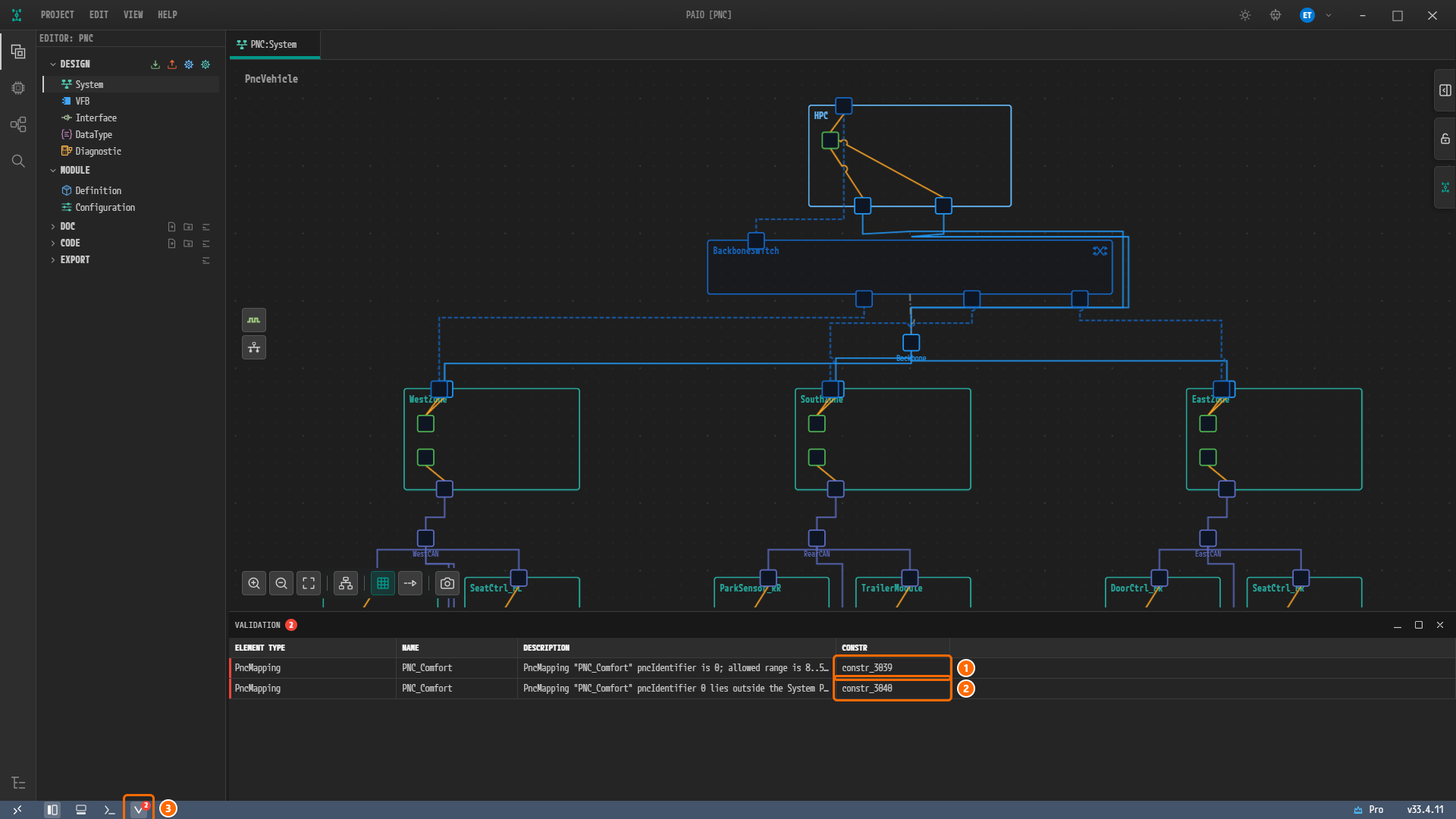
Figure 3-6. The screen after saving, with the VALIDATION panel open. ① The
constr_3039error row, ② theconstr_3040error row, ③ the validation icon (V) in the status bar. The red badge2next to the panel title and the one on the validation icon are both the error count. -
Read what the two errors say.

Figure 3-7. The VALIDATION panel. ELEMENT TYPE is
PncMappingand NAME isPNC_Comfort. ①constr_3039, ②constr_3040. The DESCRIPTION column is cut off at the end because of its length.CONSTR DESCRIPTION (full sentence) constr_3039PncMapping "PNC_Comfort" pncIdentifier is 0; allowed range is 8..511. pncIdentifier is the ABSOLUTE bit position of the PNC in the NM PDU (R25-11 TPS_SystemTemplate). constr_3040PncMapping "PNC_Comfort" pncIdentifier 0 lies outside the System PNC vector bits 16..63 (pncVectorOffset=2, pncVectorLength=6). pncIdentifier is the ABSOLUTE bit position of the PNC in the NM PDU (R25-11 TPS_SystemTemplate). An id counted from the vector start instead of the NM PDU start is off by pncVectorOffset × 8 = 16; the System's PncMappings share one counting, so every one of them moves by that amount, the ones inside the range too. -
Click the
constr_3040row. The PNC dialog reopens with the offending PNC 0 PNC_Comfort selected. The offending item gets a red border, and hovering over it shows the error text as a tooltip.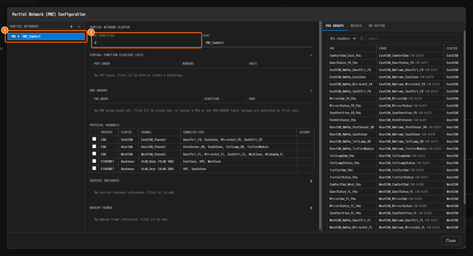
Figure 3-8. Clicking the error row takes you straight to the place to fix. ① The offending PNC entry (red border), ② the field to fix, PNC IDENTIFIER.
-
Type
17in PNC IDENTIFIER and pressEnter. The list entry changes to PNC 17 PNC_Comfort.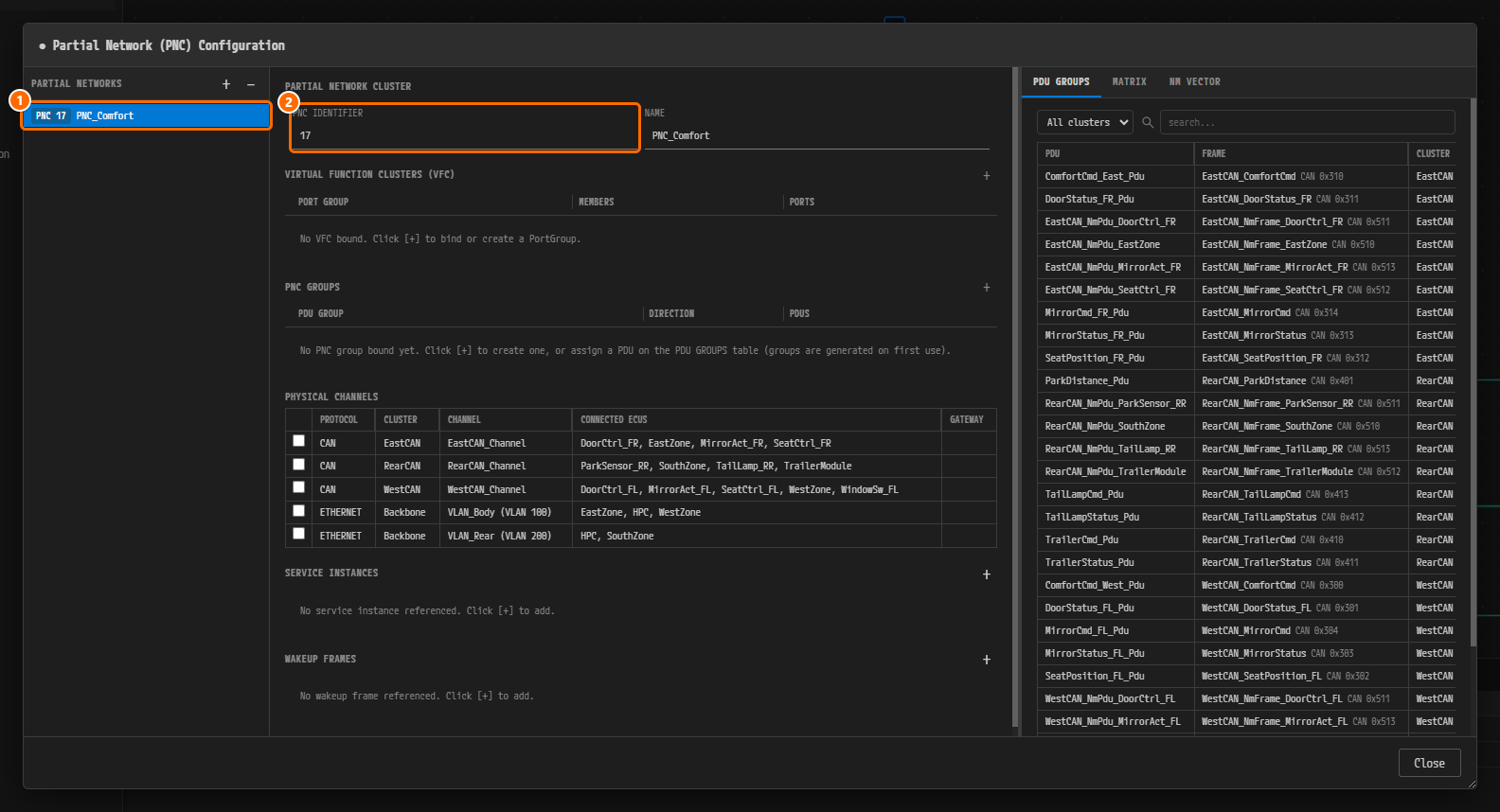
Figure 3-9. ① The list entry PNC 17 PNC_Comfort, ② PNC IDENTIFIER =
17. The ● marker appears in front of the title again. -
Press
Ctrl+Sto save and Close to close the dialog. -
The save re-runs validation, so there is nothing to click. The VALIDATION panel, still open at the bottom of the screen, shows "No validation issues.", and the red badges on the panel title and on the validation icon disappear.

Figure 3-10. The VALIDATION panel after correcting the identifier. "No validation issues."
Note. The badge on the validation icon disappears when the count drops to zero, but the tooltip of the icon keeps the last count,
Validation: 2 error(s), 0 warning(s), 0 info(s). The VALIDATION panel shows the current result.
Why Start at 17?
Design rationale. A PNC identifier is a bit number in the PNC bit vector inside the NM PDU. The usable numbers are determined by PNC VECTOR OFFSET and PNC VECTOR LENGTH on the SYSTEM, which in this example gives
16..63(constr_3040). The general range8..511fromconstr_3039must be satisfied as well. Where you read and enter those two values, and therefore why the numbers are 17, 18, and 19, is covered in Setting the PNC Bit Vector.
Adding the Remaining PNCs
-
Click the PNC button (Figure 3-1) to reopen the PNC dialog.
-
Click the [+] button. A new PNC 0 Pnc_0 entry appears.
-
Type
18in PNC IDENTIFIER and pressEnter. TypePNC_ParkAssistin NAME and pressEnter. -
In the same way, click the [+] button once more and enter PNC IDENTIFIER
19and NAMEPNC_Trailer. -
Press
Ctrl+Sto save. The list shows the three entries in identifier order.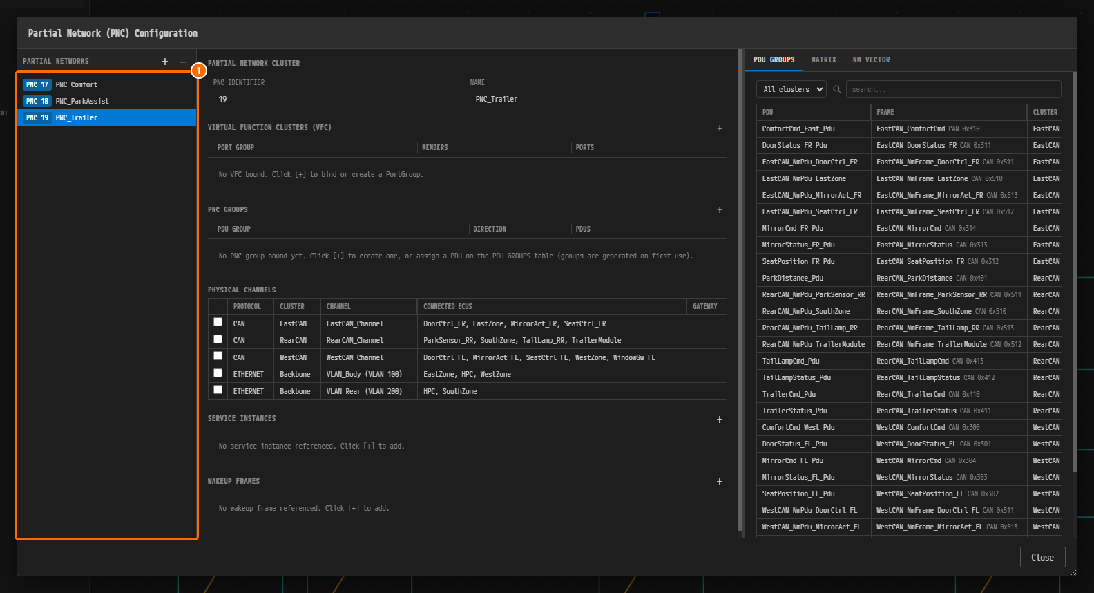
Figure 3-11. ① The PARTIAL NETWORKS list contains PNC 17 PNC_Comfort, PNC 18 PNC_ParkAssist, and PNC 19 PNC_Trailer. The PNC IDENTIFIER of the selected
PNC_Traileris19. -
Click Close. The save re-ran validation, and it still reports zero errors.
Setting the PNC Bit Vector
A PNC identifier is a bit number in the PNC bit vector inside the NM PDU. Which byte of the NM PDU that vector starts at, and how many bytes it occupies, is determined by PNC VECTOR OFFSET and PNC VECTOR LENGTH, of which there is exactly one per SYSTEM. You check and enter both values on the NM VECTOR tab of the PNC dialog.
-
Click the PNC button (Figure 3-1) to reopen the Partial Network (PNC) Configuration dialog.
-
Click the NM VECTOR tab in the view on the right.
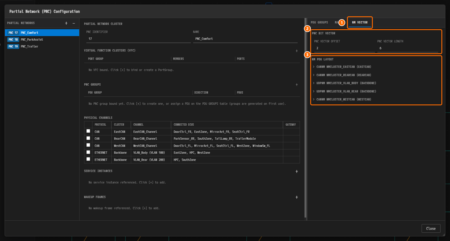
Figure 3-12. The NM VECTOR tab of the PNC dialog. ① The NM VECTOR tab, ② the PNC BIT VECTOR section, ③ the NM PDU LAYOUT section. NM PDU LAYOUT has five NM cluster headers, all collapsed at first.
-
Check that PNC VECTOR OFFSET in the PNC BIT VECTOR section is
2and PNC VECTOR LENGTH is6. If a value differs, click the field and enter it.
Figure 3-13. The PNC BIT VECTOR section. ① PNC VECTOR OFFSET =
2, ② PNC VECTOR LENGTH =6.Note. The two fields are not read-only; you can type into them. Change a value and press
Ctrl+Sand it is written toSYSTEM.io.model. If you leave both fields empty, PAIO uses2and6as defaults, but those defaults are not written to the model file. This example states both values in the model explicitly. -
In NM PDU LAYOUT, click the
CANNM NMCLUSTER_WESTCAN (WESTCAN)header to expand it. In your own project NM is not turned on for any cluster yet at this point, so the section shows a single layout without cluster headers; the cluster headers appear after you turn NM on in NM Configuration.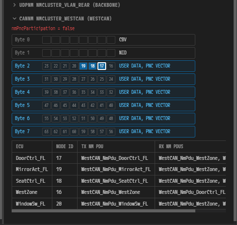
Figure 3-14. The NM PDU layout of
NmCluster_WestCAN. One row is one byte of the NM PDU, and the eight cells are bit 7..0 from the left. Byte 0 = CBV, Byte 1 = NID, Byte 2 to 7 = USER DATA, PNC VECTOR. The cells in the Byte 2 row are23 22 21 20 19 18 17 16from the left, and19,18, and17among them are filled. The table below shows this NM cluster's ECU, NODE ID, TX NM PDU, and RX NM PDUS, and is read-only.Note. The red
nmPncParticipation = falsebelow the header means this NM cluster does not carry PNCs yet. It disappears once you set NM PNC PARTICIPATION to YES in NM Configuration. -
(To see the effect) Change PNC VECTOR LENGTH to
4. The PNC VECTOR range shrinks to Byte 2 through 5, and only USER DATA remains in Byte 6 and Byte 7.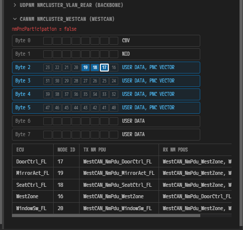
Figure 3-15. PNC VECTOR LENGTH changed to
4. PNC VECTOR occupies only Byte 2 through 5. -
Set PNC VECTOR LENGTH back to
6, pressCtrl+Sto save, and click Close. The save re-runs validation, and it still reports zero errors.
Design rationale. These two values determine the range of numbers usable as PNC identifiers. The first bit is PNC VECTOR OFFSET × 8 = 2 × 8 = 16, and the last bit is (PNC VECTOR OFFSET + PNC VECTOR LENGTH) × 8 − 1 = 8 × 8 − 1 = 63. This calculation is why the
constr_3040message you saw in Checking and Fixing the Validation Error reported the range as16..63. Within that range, this example leaves 16 unused and uses 17, 18, and 19. All three numbers fit inside the single Byte 2, so you can read a connector's filter mask as one byte.
Entering PNC Attributes on Connectors
The PNC gateway role and the wakeup condition are recorded on the connector (the point where an ECU attaches to a channel), not on the ECU. The reason is that one and the same zone ECU can have different roles on its CAN connector and on its Ethernet connector.
Enter WestZone_CanFd_Conn as the worked example, then enter the remaining connectors the same way, following the Connector Values in Full table.
Entering WestZone_CanFd_Conn
-
On the canvas, click the CAN connector (the small rectangle)
WestZone_CanFd_Connon the lower boundary of theWestZonenode. If the properties panel is collapsed, click the top one of the three buttons on the right edge of the canvas (the properties panel button, top right in Figure 3-1) to expand it. -
Check that the title of the properties panel on the right is CAN CONNECTOR and that NAME is
WestZone_CanFd_Conn. The PARTIAL NETWORK section further down is expanded by default. At first all three PNC GATEWAY TYPE buttons are off, the grid title is PNC FILTER ARRAY MASKS, and the filled cell count shows(0/6). The grid's six cells sit in two rows of three: Byte 0 to 2, then Byte 3 to 5.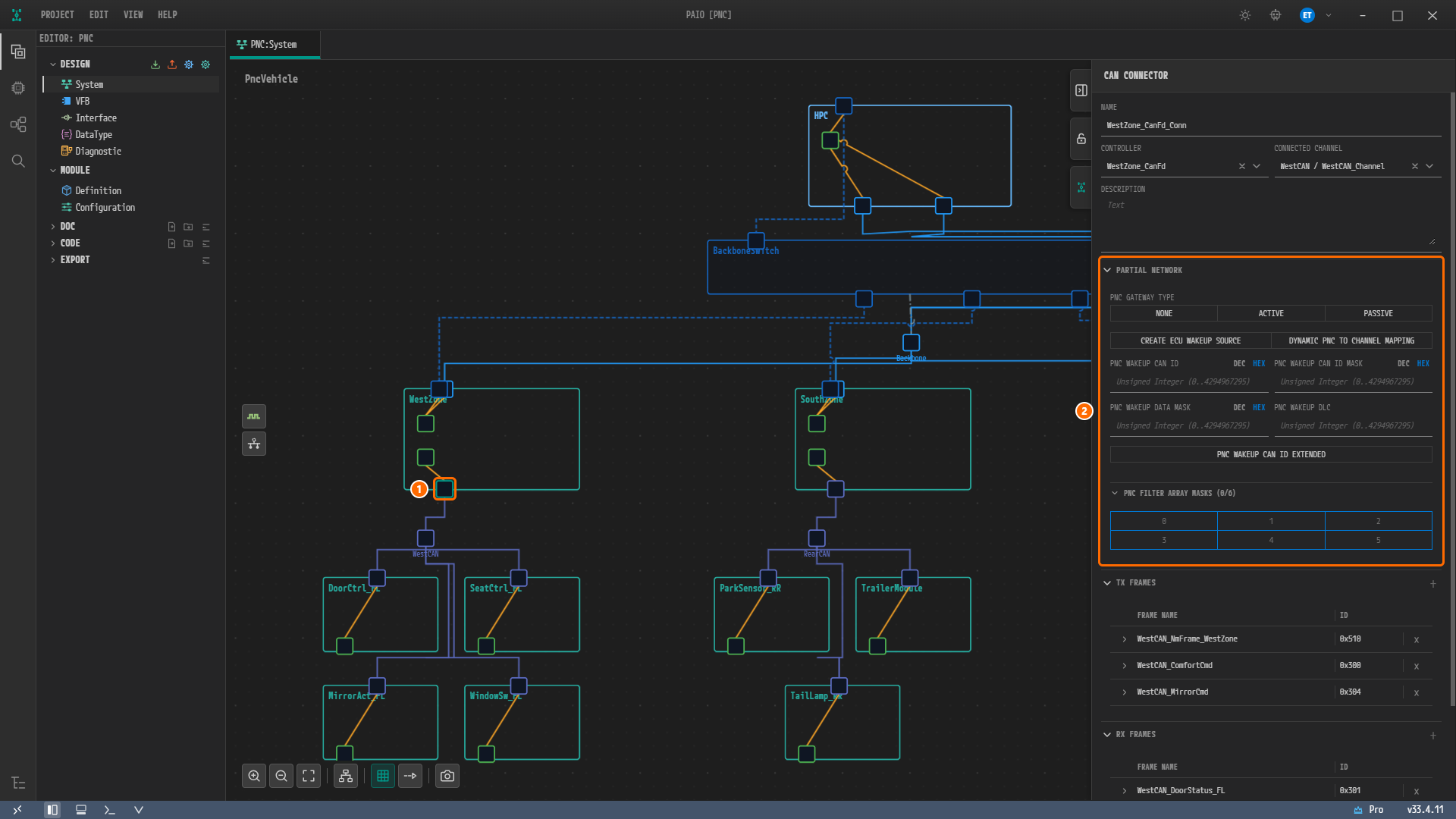
Figure 3-16. ① The selected connector
WestZone_CanFd_Conn. ② The PARTIAL NETWORK section of the properties panel. CONTROLLER isWestZone_CanFdand CONNECTED CHANNEL isWestCAN / WestCAN_Channel. -
In PNC GATEWAY TYPE, click ACTIVE.
-
Click CREATE ECU WAKEUP SOURCE to turn it on. When it is on, the button is highlighted in blue.
-
Type
500in PNC WAKEUP CAN ID. The DEC | HEX switch to the right of the field name defaults to HEX, so the value appears as0x500. -
Type
700in PNC WAKEUP CAN ID MASK. It appears as0x700. -
Type
8in PNC WAKEUP DLC. -
Click the first cell of the PNC FILTER ARRAY MASKS grid (Byte 0, placeholder
0), type02, and pressEnter. It appears as0x02, and the cell count in the grid title changes to(1/6).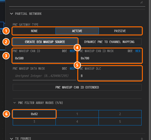
Figure 3-17. The PARTIAL NETWORK section once filled in. ① PNC GATEWAY TYPE = ACTIVE, ② CREATE ECU WAKEUP SOURCE on, ③ PNC WAKEUP CAN ID =
0x500, ④ PNC WAKEUP CAN ID MASK =0x700, ⑤ PNC WAKEUP DLC =8, ⑥ Byte 0 =0x02.Note. The grid's cell count of 6 is the SYSTEM's
pncVectorLength. Cells you leave empty are saved as0x00, so you do not have to type00into Byte 1 through 5 separately. If you save and select the connector again, all cells appear filled as(6/6), as in Figure 3-20 of the finished example. -
Leave PNC WAKEUP DATA MASK, DYNAMIC PNC TO CHANNEL MAPPING, and PNC WAKEUP CAN ID EXTENDED empty or off.
-
A dirty marker appears next to the editor tab PNC:System. Press
Ctrl+Sto save.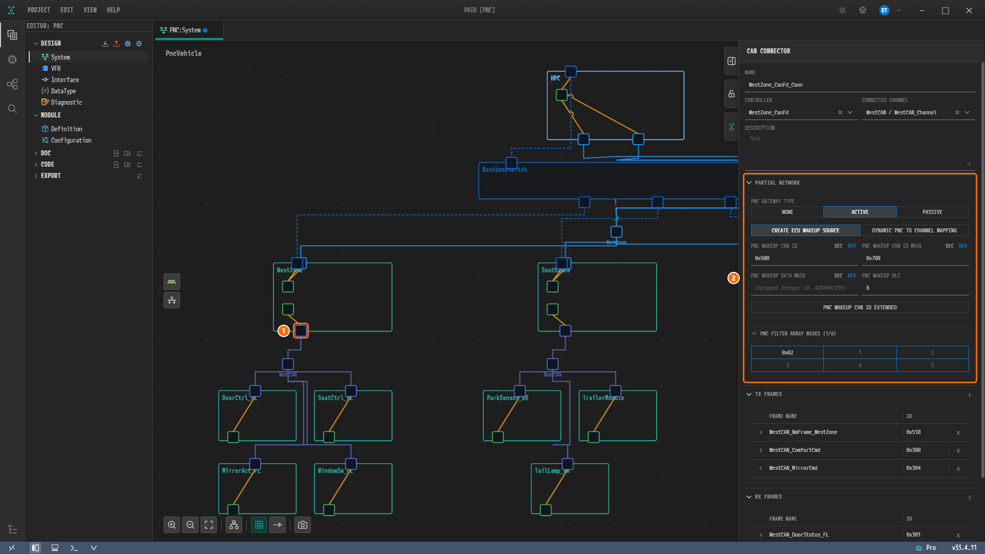
Figure 3-18. The whole window once filled in (before saving). A dirty marker is visible next to the tab name PNC:System. ① The connector, ② the PARTIAL NETWORK section.
What the Wakeup CAN ID and Mask Mean
Design rationale. Call the ID of a received CAN frame F. A frame counts as a wakeup frame when (F AND
0x700) =0x500, that is, the whole0x500..0x5FFblock. This example sets the NM frame ID to0x510+ node ID (see Signals, PDUs, Frames, and I-PDU Groups), so every NM frame falls inside that block. AUTOSAR does not define a CAN ID range for NM; this value follows OEM network design practice.
Calculating the Filter Mask
The filter mask expresses, as a byte array, which PNC bits pass through this connector. For a single PNC identifier, calculate it as follows.
byteIndex = quotient of pncId / 8 − pncVectorOffset    # 17 / 8 = 2, 2 − 2 = 0 → Byte 0
bit       = remainder of pncId / 8                     # 17 mod 8 = 1
value     = 2 ^ bit                                    # 2 ^ 1 = 0x02
When one connector passes several PNCs, OR the values together within the same byte. For example, the SouthZone side passes both PNC 18 and PNC 19, so its Byte 0 = 0x04 | 0x08 = 0x0C. The array length must equal pncVectorLength (6) (constr_3686).
Ethernet Connectors and HPC Connectors
The PARTIAL NETWORK section of an Ethernet connector has no wakeup CAN ID fields. It has only PNC GATEWAY TYPE, the two toggles, and PNC FILTER ARRAY MASKS. You enter them the same way as for a CAN connector.
The connectors of the HPC node (HPC_Eth_Body_Conn, HPC_Eth_Rear_Conn) do not show the PNC GATEWAY TYPE field at all. The HPC is an AP machine, and the PNC gateway type exists only on the connectors of CP ECUs. On HPC connectors you enter only the filter mask.
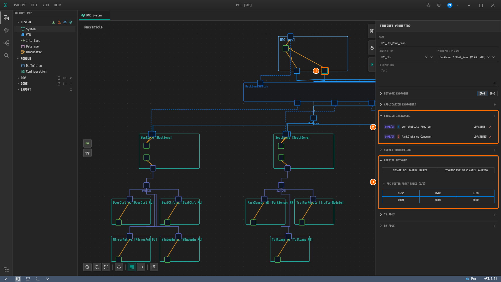
Figure 3-19. HPC_Eth_Rear_Conn selected in the finished example. ① The connector, ② SERVICE INSTANCES, ③ PARTIAL NETWORK. The properties panel title is ETHERNET CONNECTOR and CONNECTED CHANNEL is Backbone / VLAN_Rear (VLAN: 200). The name in brackets after a node name, such as WestZone [WestZone], is the composition mapped to that node in the finished example.
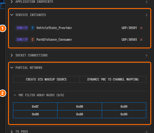
Figure 3-20. The properties panel of Figure 3-19, enlarged. ① SERVICE INSTANCES has VehicleState_Provider (P) and ParkDistance_Consumer (C) bound to it. You create these bindings in Interfaces and SOME/IP Services. ② PARTIAL NETWORK has no gateway type, only the two toggles (both off) and PNC FILTER ARRAY MASKS (6/6) = 0x0C 0x00 0x00 0x00 0x00 0x00. Between ① and ② is the collapsed SOCKET CONNECTIONS section.
VLAN_Body can have only one active gateway, so EastZone_Eth_Conn is PASSIVE. The gateway of VLAN_Rear is SouthZone_Eth_Conn (ACTIVE).
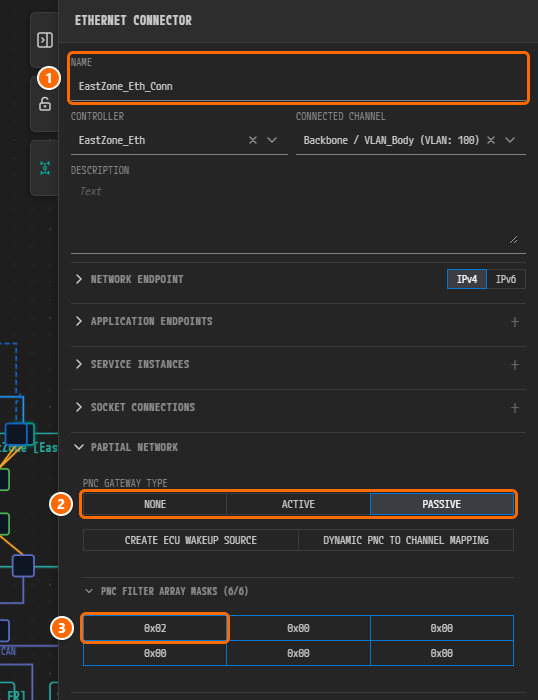
Figure 3-21. EastZone_Eth_Conn (finished example). ① NAME, ② PNC GATEWAY TYPE = PASSIVE, ③ Byte 0 = 0x02 (PNC_Comfort). CONNECTED CHANNEL is Backbone / VLAN_Body (VLAN: 100).
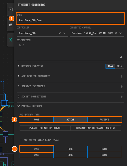
Figure 3-22. SouthZone_Eth_Conn (finished example). ① NAME, ② PNC GATEWAY TYPE = ACTIVE, ③ Byte 0 = 0x0C (PNC_ParkAssist + PNC_Trailer). CONNECTED CHANNEL is Backbone / VLAN_Rear (VLAN: 200).
Caution. When the properties panel is expanded, it covers the right side of the canvas (the
EastZoneside) and you cannot click the connectors there. Either collapse the panel with the properties panel button, click the connector, and expand the panel again, or drag the canvas to bring the connector into view and then click it.
Connector Values in Full
Enter the remaining connectors the same way. Only Byte 0 of the filter mask is listed; Byte 1 through 5 are all 0x00. An "—" marks an item to leave empty or off.
| Connector | Channel | PNC GATEWAY TYPE | CREATE ECU WAKEUP SOURCE | WAKEUP CAN ID / MASK / DLC | Byte 0 | Rationale |
|---|---|---|---|---|---|---|
WestZone_CanFd_Conn | WestCAN | ACTIVE | on | 0x500 / 0x700 / 8 | 0x02 | The only gateway on WestCAN |
EastZone_CanFd_Conn | EastCAN | ACTIVE | on | 0x500 / 0x700 / 8 | 0x02 | The only gateway on EastCAN |
SouthZone_CanFd_Conn | RearCAN | ACTIVE | on | 0x500 / 0x700 / 8 | 0x0C | The only gateway on RearCAN |
WestZone_Eth_Conn | VLAN_Body | ACTIVE | — | (no such fields) | 0x02 | Top-level coordinator for PNC_Comfort |
EastZone_Eth_Conn | VLAN_Body | PASSIVE | — | (no such fields) | 0x02 | WestZone is the single active gateway on VLAN_Body (constr_5093) |
SouthZone_Eth_Conn | VLAN_Rear | ACTIVE | — | (no such fields) | 0x0C | Top-level coordinator for PNC_ParkAssist and PNC_Trailer |
_CAN_Conn of DoorCtrl_FL, SeatCtrl_FL, MirrorAct_FL, WindowSw_FL | WestCAN | NONE | on | — | 0x02 | Not a gateway, but a wakeup source |
_CAN_Conn of DoorCtrl_FR, SeatCtrl_FR, MirrorAct_FR | EastCAN | NONE | on | — | 0x02 | Not a gateway, but a wakeup source |
ParkSensor_RR_CAN_Conn | RearCAN | NONE | on | — | 0x04 | Only its own PNC (18) bit |
TrailerModule_CAN_Conn, TailLamp_RR_CAN_Conn | RearCAN | NONE | on | — | 0x08 | Only its own PNC (19) bit |
HPC_Eth_Body_Conn | VLAN_Body | (no such field) | — | (no such fields) | 0x02 | An AP machine is not a gateway |
HPC_Eth_Rear_Conn | VLAN_Rear | (no such field) | — | (no such fields) | 0x0C | An AP machine is not a gateway |
Once you have entered every connector, press Ctrl+S to save.
Note. The
IVC.io.modelof the finished example also records, for each CAN connector, the list of PNCs it participates in (pnc-mappings). A zone's CAN connector holds the PNCs of that bus (PNC_ComfortforWestZoneandEastZone;PNC_ParkAssistandPNC_TrailerforSouthZone), and an end ECU's CAN connector holds its own single PNC. Ethernet connectors do not have this list. In the current version these values are not shown in the properties panel and cannot be edited on screen.
Entering the PARTIAL NETWORK Values of a Node
The ECU nodes and the HPC node also have a PARTIAL NETWORK section in the properties panel. The section has the same name as the one on a connector, but different contents. The node side holds the NM request and the sleep timers.
-
On the canvas, click the header of a node (for example
WestZone) to select the node. Make sure you select the node and not a connector (a small rectangle). -
Scroll down the properties panel to find the PARTIAL NETWORK section. An ECU node has three toggles on one row: PNC NM REQUEST, PNC SYNCHRONOUS WAKEUP, and CHANNEL SYNCHRONOUS WAKEUP. If the window is narrow, the name of the third toggle is truncated, for example to
CHANNEL SYNCHRONOUS W…. -
Click PNC NM REQUEST to turn it on. When it is on, the button is highlighted in blue, like CREATE ECU WAKEUP SOURCE on a connector. The orange frame around it in Figure 3-23 is only the figure's highlight. Leave PNC SYNCHRONOUS WAKEUP and CHANNEL SYNCHRONOUS WAKEUP off.
-
Type
0.5in PNC PREPARE SLEEP TIMER and2in PN RESET TIME.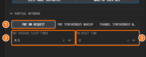
Figure 3-23. The PARTIAL NETWORK section of the
WestZonenode. ① PNC NM REQUEST turned on, ② PNC PREPARE SLEEP TIMER =0.5s, ③ PN RESET TIME =2s. A unit selector sits to the right of each of the two timer fields.Note. Both timers are fields that carry a value together with a unit. The unit selector offers ns, us, ms, and s, and the default unit for an empty field is s. So typing
0.5and2as they are saves0.5s and2s. Changing the unit changes only the display; the saved value stays the same. -
Enter the remaining nodes as in the table below, then press
Ctrl+Sto save.
| Node | PNC NM REQUEST | PNC SYNCHRONOUS WAKEUP | PNC PREPARE SLEEP TIMER | PN RESET TIME / PN RESET TIMER |
|---|---|---|---|---|
WestZone, SouthZone, EastZone | on | off | 0.5 s | 2 s (PN RESET TIME) |
| The 10 end ECUs | on | off | 0.5 s | 2 s (PN RESET TIME) |
HPC | (no such field) | (no such field) | 0.5 s | 2 s (PN RESET TIMER) |
HPC is an AP machine, so its PARTIAL NETWORK section has no toggles, only the two timer fields. The second field is also named PN RESET TIMER rather than the ECU's PN RESET TIME. Enter the same values as for an ECU, 0.5 s and 2 s.

Figure 3-24. The PARTIAL NETWORK section of the HPC node. ① PNC PREPARE SLEEP TIMER = 0.5 s, ② PN RESET TIMER = 2 s. Unlike the ECU node in Figure 3-23, there are no toggles.
Note. The finished example files state PNC SYNCHRONOUS WAKEUP = false explicitly on the three zone ECUs and leave the value unset on the end ECUs, but on screen both cases appear as an off button.
Assigning PNCs to Switch Ports
PNC MAPPINGS on a switch port expresses which PNCs this port is used for when they are awake. The candidates are the PNC catalog you defined in this chapter, and the list shows the name together with the identifier, for example "PNC_Comfort (PNC 17)".
-
On the canvas, double-click the
BackboneSwitchnode. The Ethernet Switch Configuration [BackboneSwitch] workbench opens. -
In the switch diagram on the left of the workbench, click
Port_1. The COUPLING PORT panel on the right shows the port configuration. -
Click the PNC MAPPINGS field to open the checkbox list. Check
PNC_Comfort (PNC 17)in the checklist and pressEscto close the list.Note. If no candidates appear in the dropdown, close the workbench with Close and double-click
BackboneSwitchto open it again. The candidates are the PNC catalog you saved in the PNC dialog, shown in the formname (PNC number).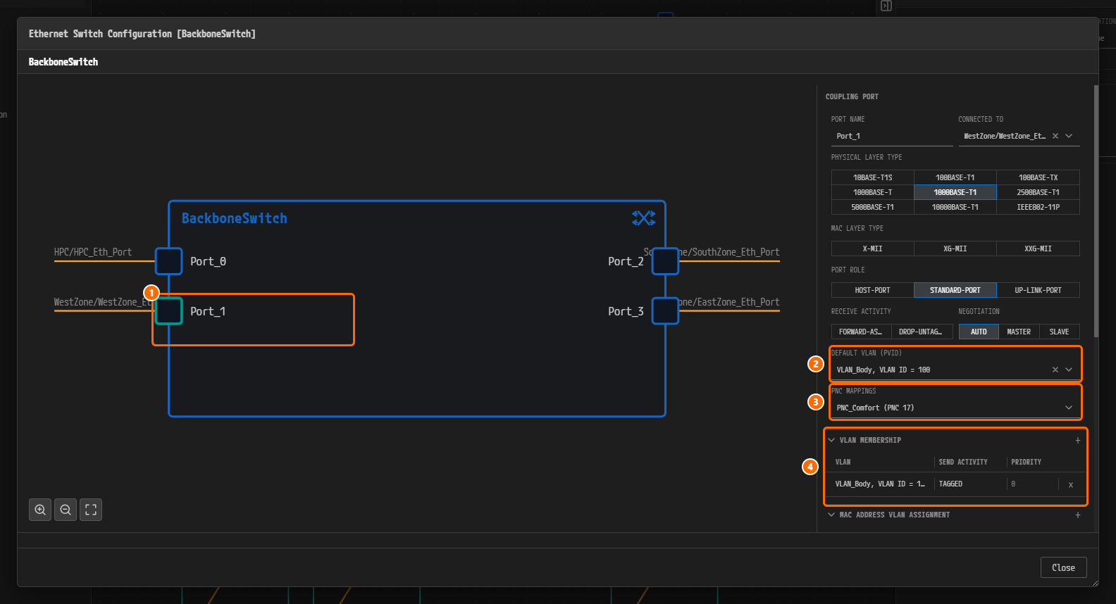
Figure 3-25.
Port_1selected in the BackboneSwitch workbench of the finished example. ①Port_1, ② DEFAULT VLAN (PVID) =VLAN_Body, VLAN ID = 100, ③ PNC MAPPINGS =PNC_Comfort (PNC 17), ④ VLAN MEMBERSHIP (VLAN_Body, TAGGED). The connection labels and CONNECTED TO values of some ports are cut off because of their length.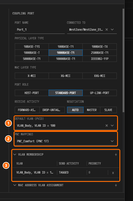
Figure 3-26. The COUPLING PORT panel of Figure 3-25, enlarged. ① DEFAULT VLAN (PVID), ② PNC MAPPINGS, ③ VLAN MEMBERSHIP. PORT ROLE is STANDARD-PORT and PHYSICAL LAYER TYPE is 1000BASE-T1.
-
Assign the remaining ports as in the table below. You can check several PNCs on one port.
Port Connects to VLAN PNC MAPPINGS Port_0HPC VLAN_Body,VLAN_RearPNC_Comfort,PNC_ParkAssist,PNC_TrailerPort_1WestZone VLAN_BodyPNC_ComfortPort_2SouthZone VLAN_RearPNC_ParkAssist,PNC_TrailerPort_3EastZone VLAN_BodyPNC_Comfort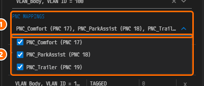
Figure 3-27. The PNC MAPPINGS dropdown of
Port_0, opened (finished example). ① When closed, the field shows the checked PNCs joined by commas, and cuts off the end if the text is long. ② All three candidatesPNC_Comfort (PNC 17),PNC_ParkAssist (PNC 18), andPNC_Trailer (PNC 19)are checked. This is the port toward the HPC, so all three PNCs pass through it. -
Press
Ctrl+Sin the workbench to apply the configuration to the System editor, then click Close. If you click Close without applying, a "Do you want to save the changes?" confirmation window appears. -
Press
Ctrl+Sin the System editor to save.
Note. In the finished example the same PNCs are assigned on the Ethernet controller ports as well.
HPC_Eth_Porthas all three PNCs,WestZone_Eth_PortandEastZone_Eth_PorthavePNC_Comfort, andSouthZone_Eth_PorthasPNC_ParkAssistandPNC_Trailer.
NM Configuration
An NM cluster is a group of nodes on one communication cluster that wake up and go to sleep under the same rules. The PNC bit vector travels inside NM PDUs, so for PNCs to work, the NM cluster of that bus must be marked as carrying PNCs (NM PNC PARTICIPATION = YES) and the mandatory NM timing attributes must be filled in. Each NM node must also have an NM NODE ID and the NM-PDUs it sends and receives.
Work through NmCluster_WestCAN and the CAN NM node of WestZone as the worked example, then repeat the same steps for the rest, following the NM Values in Full table.
Note. You do not create NM clusters and NM nodes yourself. They are created automatically from the communication clusters and connectors you drew in Topology Design, on every communication cluster where NM is turned on. That is why the list has no add or delete buttons, and why the three fields NM CLUSTER, CONTROLLER, and CONNECTOR of an NM node are read-only. NM is off on a newly drawn cluster, so in your own project you first turn it on in each cluster's dialog (step 2 of Filling In NmCluster_WestCAN). After that, what you do in this section is fill in values on elements that already exist.
Finding the Missing Mandatory NM Attributes
-
PAIO validates the project by itself, so there is nothing to click to run validation. If the VALIDATION panel is not open, click the validation icon (V) in the status bar to open it. If the mandatory attributes of
NmCluster_WestCANare empty, you see four errors, and the validation icon carries a red badge4. In your own project NM is still off at this point, and a cluster gets defaults for these four attributes when you turn NM on (see the Caution after Figure 3-32), so you do not see these errors; the figure and the table below show what they report.
Figure 3-28. The VALIDATION panel. ELEMENT TYPE is
CanNmClusterand NAME isNmCluster_WestCAN. Three of the four DESCRIPTION cells are cut off at the end because of their length.CONSTR Missing attribute Where you fill it in constr_9157nmBusloadReductionActiveNM BUSLOAD REDUCTION ACTIVE in the CHANNEL section constr_9158nmImmediateNmTransmissionsNM IMMEDIATE NM TRANSMISSIONS in the NM TIMING CONFIGURATION section constr_9159nmMessageTimeoutTimeNM MESSAGE TIMEOUT TIME in the NM TIMING CONFIGURATION section constr_9162nmRemoteSleepIndicationTimeNM REMOTE SLEEP INDICATION TIME in the NM TIMING CONFIGURATION section
Filling In NmCluster_WestCAN
-
On the System editor canvas, double-click the CAN cluster node below
WestZone. Its nameWestCANis written below it, and hovering over it shows the labelWestCAN (Can, 500 kbps).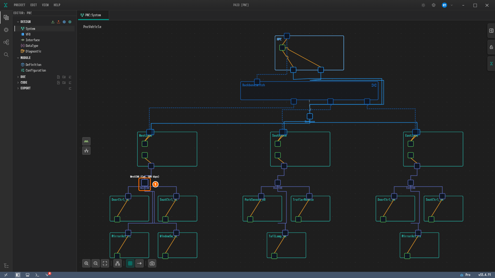
Figure 3-29. The System editor canvas. ① The
WestCANcluster node to double-click. -
The Communication Cluster Configuration [WestCAN] dialog opens on the CLUSTER tab. Click the CAN NM CLUSTER tab. If NM is still off on this cluster, the tab reads NM CLUSTER instead, with a hollow dot and a dimmed name, and its form cannot be edited. Hovering over it shows the tooltip
Disabled. Right-click to enable., and right-clicking it opens a menu with one item, Enable. Choose Enable. The tab then reads CAN NM CLUSTER with a filled dot, and the form can be edited. The left side is the NM CONFIGURATION form, and the right side is the read-only NM STATE MACHINE diagram.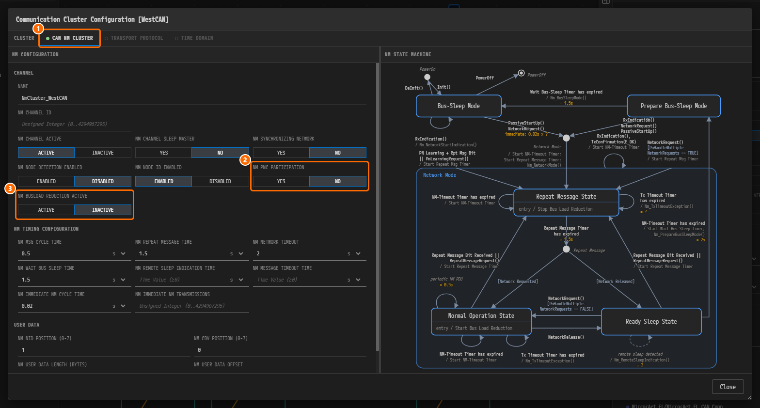
Figure 3-30. Communication Cluster Configuration [WestCAN]. ① The CAN NM CLUSTER tab, ② NM PNC PARTICIPATION (still NO), ③ NM BUSLOAD REDUCTION ACTIVE. The set of tabs depends on the protocol. A CAN cluster has CLUSTER, CAN NM CLUSTER, TRANSPORT PROTOCOL, and TIME DOMAIN. The dot in front of a feature tab shows whether that feature is on: filled for CAN NM CLUSTER, hollow with a dimmed tab name for TRANSPORT PROTOCOL and TIME DOMAIN, which are off on this cluster.
-
In the CHANNEL section, change NM PNC PARTICIPATION to YES.
-
Click NM BUSLOAD REDUCTION ACTIVE to ACTIVE and then back to INACTIVE. The example value is INACTIVE.
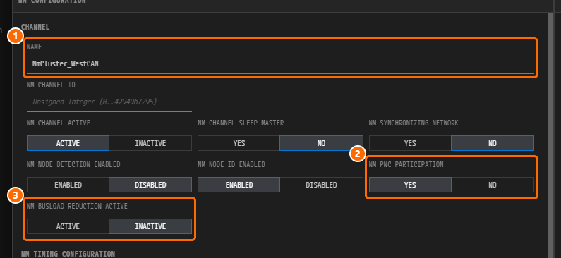
Figure 3-31. The CHANNEL section once filled in. ① NAME =
NmCluster_WestCAN, ② NM PNC PARTICIPATION = YES, ③ NM BUSLOAD REDUCTION ACTIVE = INACTIVE. Leave NM CHANNEL ID empty.Caution. A two-state button that has no value yet looks on screen as if one side were pressed, but the model holds no value. Clicking the side that already looks pressed does nothing. So when an item such as NM BUSLOAD REDUCTION ACTIVE has no value and the side you want already looks pressed, you have to click the other side once and then click back to commit the value.
-
In the NM TIMING CONFIGURATION section, enter NM MESSAGE TIMEOUT TIME
0.1, NM REMOTE SLEEP INDICATION TIME1, and NM IMMEDIATE NM TRANSMISSIONS5. Check the remaining fields in the same section as well — NM MSG CYCLE TIME0.5, NM REPEAT MESSAGE TIME1.5, NM WAIT BUS SLEEP TIME1.5, NM NETWORK TIMEOUT2, NM IMMEDIATE NM CYCLE TIME0.02— and enter the value wherever it differs or is empty.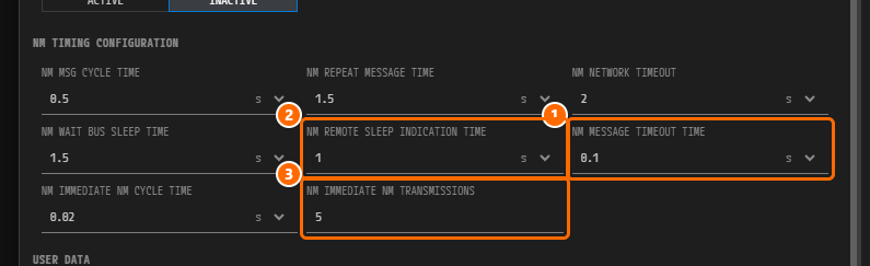
Figure 3-32. The NM TIMING CONFIGURATION section once filled in. ① NM MESSAGE TIMEOUT TIME =
0.1s, ② NM REMOTE SLEEP INDICATION TIME =1s, ③ NM IMMEDIATE NM TRANSMISSIONS =5. The remaining fields on screen are NM MSG CYCLE TIME0.5s, NM REPEAT MESSAGE TIME1.5s, NM NETWORK TIMEOUT2s, NM WAIT BUS SLEEP TIME1.5s, and NM IMMEDIATE NM CYCLE TIME0.02s.Note. As with the node timers, the time fields carry a unit selector (ns, us, ms, s) and the default unit is s. So you can type
0.1and1as they are. NM IMMEDIATE NM TRANSMISSIONS is a count, so it has no unit selector.Caution. An NM cluster created automatically comes with default values: NM MSG CYCLE TIME
0.5, NM REPEAT MESSAGE TIME1.0, NM WAIT BUS SLEEP TIME1.5, NM NETWORK TIMEOUT2, NM MESSAGE TIMEOUT TIME2, and NM REMOTE SLEEP INDICATION TIME1, plus NM BUSLOAD REDUCTION ACTIVE INACTIVE and NM IMMEDIATE NM TRANSMISSIONS0on a CanNm cluster. Of these, NM REPEAT MESSAGE TIME, NM MESSAGE TIMEOUT TIME, and NM IMMEDIATE NM TRANSMISSIONS differ from the example values1.5,0.1, and5, so you must change them. NM IMMEDIATE NM CYCLE TIME and the four USER DATA fields of the next step are empty, so you must type them in. The figure above already shows the example values. -
Scroll the form down to the USER DATA section at its end. Check the four values there and enter them if they are empty. They are NM NID POSITION (0-7)
1, NM CBV POSITION (0-7)0, NM USER DATA OFFSET2, and NM USER DATA LENGTH (BYTES)6.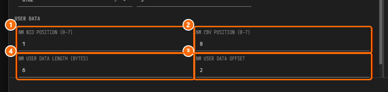
Figure 3-33. The USER DATA section. ① NM NID POSITION (0-7) =
1, ② NM CBV POSITION (0-7) =0, ③ NM USER DATA OFFSET =2, ④ NM USER DATA LENGTH (BYTES) =6. The last two values point at the same place as PNC VECTOR OFFSET and PNC VECTOR LENGTH in Setting the PNC Bit Vector. -
Press
Ctrl+Sto save, then click Close.
Filling In the NM Node Values of WestZone
-
On the System editor canvas, double-click the
WestZonenode. The ECU Configuration [WestZone] dialog opens on the ECU RESOURCE tab. Click the NETWORK MANAGEMENT tab.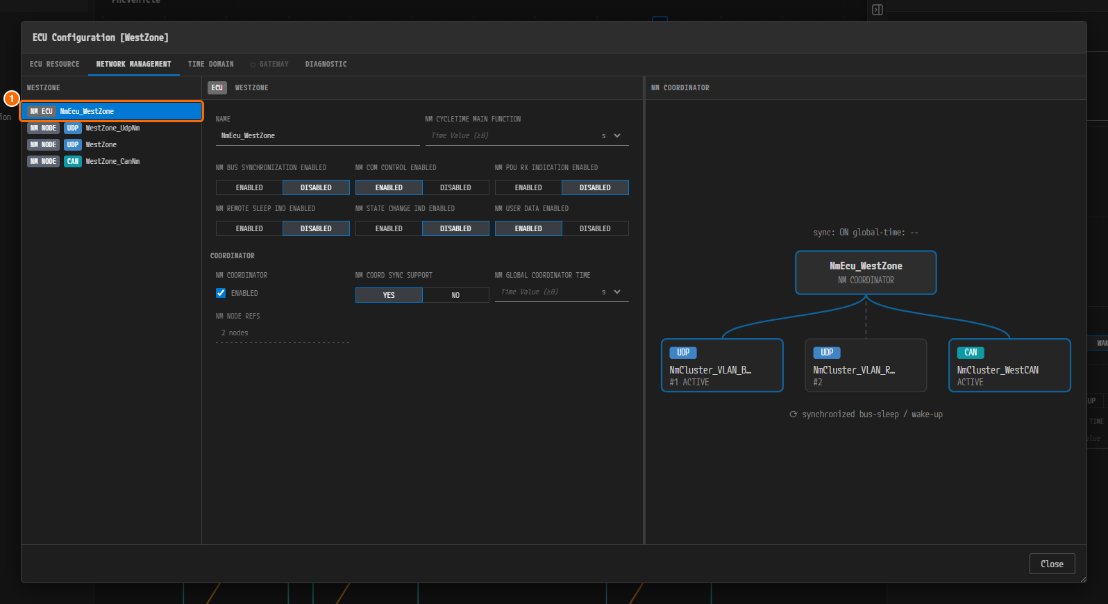
Figure 3-34. The NETWORK MANAGEMENT tab of ECU Configuration [WestZone]. ① The list on the left. It holds one NM ECU and several NM NODE entries, each with a UDP or CAN badge. The center shows the values of the selected NM ECU, and the right side is the NM COORDINATOR diagram. The list is created automatically from the topology, so it has no add or delete buttons. The dialog's tabs are ECU RESOURCE, NETWORK MANAGEMENT, TIME DOMAIN, GATEWAY (off, with a hollow dot), and DIAGNOSTIC.
Note. Besides
WestZone_UdpNm, the list on this screen shows one more UDP NM node namedWestZone. This is because the finished example puts two NM clusters on the singleBackbone(see the Caution below); it does not appear in your own project. -
Select the NM node with the CAN badge. Type
16in NM NODE ID and click ACTIVE in NM COORDINATOR ROLE, becauseWestZoneis the gateway of WestCAN.Note. The NAME of an automatically created NM node is the same as the name of its node (the ECU). So the CAN node and the UDP node of
WestZonecan both appear under the nameWestZone. This tutorial renames NAME toWestZone_CanNmandWestZone_UdpNmto tell them apart, as the finished example does. When you rename a node, the coordinator reference on the NM ECU is updated along with it. The default of NM COORDINATOR ROLE is NONE, so on a gateway node you have to click ACTIVE yourself.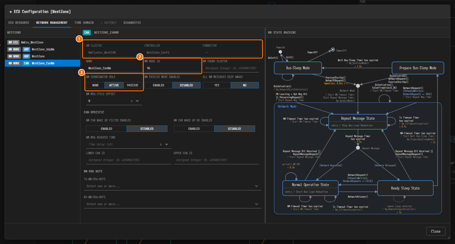
Figure 3-35.
WestZone_CanNm. ① The NM CLUSTER, CONTROLLER, and CONNECTOR rows are read-only. A CAN NM node is identified by its controller, so CONNECTOR is--. ② NM NODE ID =16, ③ NM COORDINATOR ROLE = ACTIVE. This example leaves the CAN-SPECIFIC section below empty.
Caution. Steps 3 and 4 below require the 18 NM-PDUs to exist. You create the NM-PDUs in the next chapter, Signals, PDUs, Frames, and I-PDU Groups. If you have followed the chapters in order, the candidate list is empty now, so skip steps 3 and 4 and go to step 5. After you finish Creating the NM-PDUs in Chapter 4, come back to this section and do steps 3 and 4 for every NM node. You can enter all the other NM values now.
-
In the NM-PDU REFS section, click the TX-NM-PDU-REFS field. A checkbox list opens, offering every NM-PDU created in Signals, PDUs, Frames, and I-PDU Groups as a candidate. Check only
WestCAN_NmPdu_WestZoneand pressEscto close it.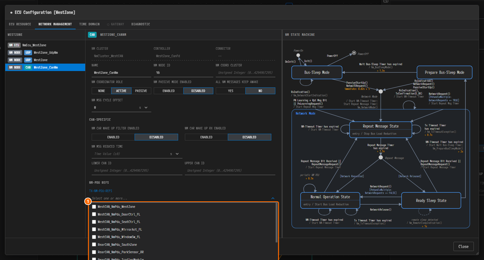
Figure 3-36. ① The checkbox list of TX-NM-PDU-REFS. NM-PDUs of other buses appear here too, so pick by the bus name in front of the PDU name (
WestCAN_). -
In the RX-NM-PDU-REFS field, check the remaining four of the same cluster —
WestCAN_NmPdu_DoorCtrl_FL,WestCAN_NmPdu_SeatCtrl_FL,WestCAN_NmPdu_MirrorAct_FL, andWestCAN_NmPdu_WindowSw_FL— and pressEsc.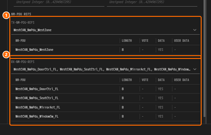
Figure 3-37. The NM-PDU REFS section once assigned. ① One TX-NM-PDU-REFS, ② four RX-NM-PDU-REFS. The table below the fields shows the LENGTH, VOTE, DATA, and USER DATA of the selected NM-PDUs. All five have LENGTH
8and DATA YES.Note. TX-NM-PDU-REFS accepts at most one entry (
constr_9388). An NM node sends only its own NM-PDU and receives the rest of its cluster. -
Press
Ctrl+Sto save, then click Close. -
Each save re-runs validation, so there is nothing to click. In the VALIDATION panel,
constr_9157,constr_9158,constr_9159, andconstr_9162are all gone. If the panel is closed, click the validation icon (V) in the status bar to open it.
Figure 3-38. The VALIDATION panel after filling in the NM values. The four NM errors are gone, and the panel reads "No validation issues."
Caution. Pressing
Ctrl+Sin the Communication Cluster Configuration dialog saves the whole IVC model (IVC.io.model) again, which introduces differences from the finished example: the VLAN configuration ofBackboneis lost, a few more Ethernet NM nodes are created, and an emptytp-configis added. The CAN FD configuration of the CAN clusters is kept. NoCanTpConfigis created, because the transport protocol is a per-cluster feature that stays off here (the hollow dot on the TRANSPORT PROTOCOL tab), so the save adds no validation errors. The transport protocol (CanTp) is out of scope for this tutorial. The differences from the finished example are collected in Appendix — Differences Between Your Own Project and the Finished Example.
Differences on the Ethernet (UdpNm) Side
-
Double-click the
Backbonecluster node. The dialog again opens on the CLUSTER tab, and the NM tab is named UDP NM CLUSTER; click it. If it reads NM CLUSTER with a hollow dot, NM is still off onBackbone: turn it on with Enable as you did forWestCAN. The CHANNEL, NM TIMING CONFIGURATION, and USER DATA sections are laid out as for CAN, with one more section, NETWORK CONFIGURATION (UDP), at the bottom; scroll the form down to reach it. UdpNm does not use immediate transmission, so leave NM IMMEDIATE NM CYCLE TIME and NM IMMEDIATE NM TRANSMISSIONS empty. Fill in the rest with the same values as for CAN. NM MESSAGE TIMEOUT TIME0.1and NM REMOTE SLEEP INDICATION TIME1are mandatory on a UdpNm cluster too (constr_5222), and the four USER DATA values are the same1/0/2/6.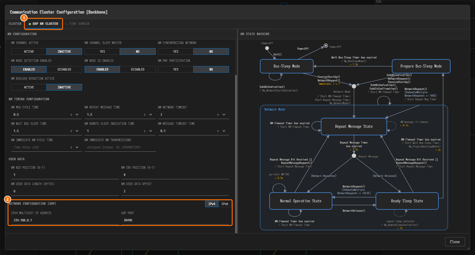
Figure 3-39. Communication Cluster Configuration [Backbone], with the form scrolled to its end. ① The UDP NM CLUSTER tab, ② the NETWORK CONFIGURATION (UDP) section. An Ethernet cluster has three tabs: CLUSTER, UDP NM CLUSTER, and TIME DOMAIN (off, with a hollow dot).
-
In the NETWORK CONFIGURATION (UDP) section, enter IPV4 MULTICAST IP ADDRESS
239.100.0.1and UDP PORT30490. The IPv4 | IPv6 switch to the right of the section header changes the address field. Use only one of the two.
Figure 3-40. The NETWORK CONFIGURATION (UDP) section. ① IPV4 MULTICAST IP ADDRESS =
239.100.0.1, ② UDP PORT =30490. -
Fill in the UDP NM nodes the same way, from the ECU dialog.
HPCopens as HPC Configuration [HPC], which has no GATEWAY tab. A UDP NM node reportsconstr_5223when NM MSG CYCLE OFFSET is empty, so enter a value even if it is0.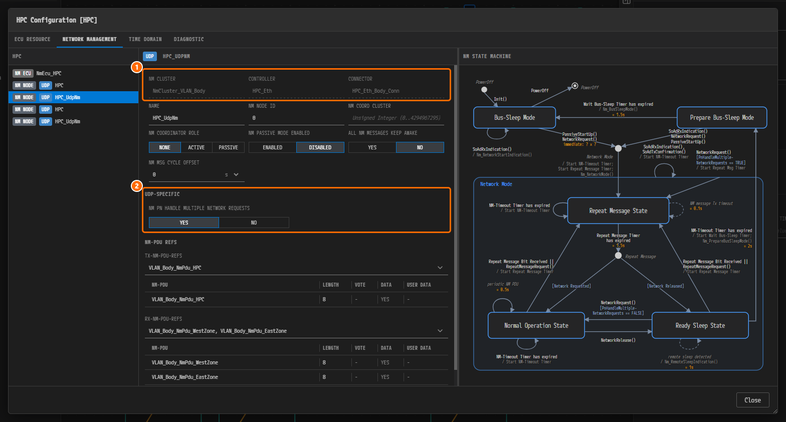
Figure 3-41. The
HPC_UdpNmnode ofHPC. ① The read-only rows. A UDP NM node is identified by its connector, so CONNECTOR is filled in withHPC_Eth_Body_Conn. ② Instead of the CAN-SPECIFIC section of a CAN node there is a UDP-SPECIFIC section, holding a single item, NM PN HANDLE MULTIPLE NETWORK REQUESTS (YES).
Caution. The example puts two NM clusters,
NmCluster_VLAN_BodyandNmCluster_VLAN_Rear, on the singleBackbone. Double-clickingBackbone, however, always opens the first one,NmCluster_VLAN_Body. The values ofNmCluster_VLAN_Rearcannot be edited on screen.
NM Values in Full
Repeat the same steps for the remaining NM clusters. Every time value is in seconds (s).
| NM cluster | Kind | Communication cluster | NM PNC PARTICIPATION | MSG CYCLE / REPEAT MESSAGE / WAIT BUS SLEEP / NETWORK TIMEOUT | REMOTE SLEEP IND / MESSAGE TIMEOUT | NID POS / CBV POS / USER DATA OFFSET / LENGTH | Protocol-specific values |
|---|---|---|---|---|---|---|---|
NmCluster_WestCAN | CanNm | WestCAN | YES | 0.5 / 1.5 / 1.5 / 2 | 1 / 0.1 | 1 / 0 / 2 / 6 | BUSLOAD REDUCTION INACTIVE, IMMEDIATE NM CYCLE TIME 0.02, IMMEDIATE NM TRANSMISSIONS 5 |
NmCluster_RearCAN | CanNm | RearCAN | YES | same | same | same | same |
NmCluster_EastCAN | CanNm | EastCAN | YES | same | same | same | same |
NmCluster_VLAN_Body | UdpNm | Backbone | YES | same | same | same | IPv4 239.100.0.1 / UDP PORT 30490 |
NmCluster_VLAN_Rear | UdpNm | Backbone | YES | same | same | same | IPv4 239.200.0.1 / UDP PORT 30490 |
The last row of the table, NmCluster_VLAN_Rear, cannot be opened on screen, as the Caution above explains. In your own project, carry on without entering that one row, and see Appendix — Differences Between Your Own Project and the Finished Example for what changes as a result.
All five clusters have NM NODE ID ENABLED = ENABLED in common. The CanNm clusters have NM CHANNEL ACTIVE = ACTIVE, NM CHANNEL SLEEP MASTER = NO, and NM NODE DETECTION ENABLED = DISABLED, while the UdpNm clusters have NM NODE DETECTION ENABLED = ENABLED. Leave NM CHANNEL ID empty on all five clusters. The Caution above applies to these two-state buttons as well: even when the side you want already looks pressed on screen, you have to click the other side once and click back for the value to enter the model.
Within each cluster, the gateway node takes the first NM node number and the remaining nodes take the numbers after it. The CAN side starts at 16 and the Ethernet side at 0. This is a choice made for this example, not a rule. NM MSG CYCLE OFFSET staggers the moment at which each node sends its NM-PDU, which reduces bus collisions.
| NM cluster | NM node | NM NODE ID | NM COORDINATOR ROLE | NM MSG CYCLE OFFSET | TX-NM-PDU-REFS |
|---|---|---|---|---|---|
NmCluster_WestCAN | WestZone_CanNm | 16 | ACTIVE | 0 | WestCAN_NmPdu_WestZone |
NmCluster_WestCAN | DoorCtrl_FL_CanNm | 17 | NONE | 0.05 | WestCAN_NmPdu_DoorCtrl_FL |
NmCluster_WestCAN | SeatCtrl_FL_CanNm | 18 | NONE | 0.10 | WestCAN_NmPdu_SeatCtrl_FL |
NmCluster_WestCAN | MirrorAct_FL_CanNm | 19 | NONE | 0.15 | WestCAN_NmPdu_MirrorAct_FL |
NmCluster_WestCAN | WindowSw_FL_CanNm | 20 | NONE | 0.20 | WestCAN_NmPdu_WindowSw_FL |
NmCluster_RearCAN | SouthZone_CanNm | 16 | ACTIVE | 0 | RearCAN_NmPdu_SouthZone |
NmCluster_RearCAN | ParkSensor_RR_CanNm | 17 | NONE | 0.05 | RearCAN_NmPdu_ParkSensor_RR |
NmCluster_RearCAN | TrailerModule_CanNm | 18 | NONE | 0.10 | RearCAN_NmPdu_TrailerModule |
NmCluster_RearCAN | TailLamp_RR_CanNm | 19 | NONE | 0.15 | RearCAN_NmPdu_TailLamp_RR |
NmCluster_EastCAN | EastZone_CanNm | 16 | ACTIVE | 0 | EastCAN_NmPdu_EastZone |
NmCluster_EastCAN | DoorCtrl_FR_CanNm | 17 | NONE | 0.05 | EastCAN_NmPdu_DoorCtrl_FR |
NmCluster_EastCAN | SeatCtrl_FR_CanNm | 18 | NONE | 0.10 | EastCAN_NmPdu_SeatCtrl_FR |
NmCluster_EastCAN | MirrorAct_FR_CanNm | 19 | NONE | 0.15 | EastCAN_NmPdu_MirrorAct_FR |
NmCluster_VLAN_Body | HPC_UdpNm | 0 | NONE | 0 | VLAN_Body_NmPdu_HPC |
NmCluster_VLAN_Body | WestZone_UdpNm | 1 | ACTIVE | 0 | VLAN_Body_NmPdu_WestZone |
NmCluster_VLAN_Body | EastZone_UdpNm | 2 | PASSIVE | 0 | VLAN_Body_NmPdu_EastZone |
NmCluster_VLAN_Rear | HPC_UdpNm | 0 | NONE | 0 | VLAN_Rear_NmPdu_HPC |
NmCluster_VLAN_Rear | SouthZone_UdpNm | 1 | ACTIVE | 0 | VLAN_Rear_NmPdu_SouthZone |
Enter NM NODE ID, NM COORDINATOR ROLE, and NM MSG CYCLE OFFSET from the table above now. Come back to this table after you finish Chapter 4 to fill in the TX-NM-PDU-REFS column and the RX-NM-PDU-REFS described below.
In RX-NM-PDU-REFS, check every other NM-PDU of the same NM cluster. For example, DoorCtrl_FL_CanNm receives four: WestCAN_NmPdu_WestZone, WestCAN_NmPdu_SeatCtrl_FL, WestCAN_NmPdu_MirrorAct_FL, and WestCAN_NmPdu_WindowSw_FL. On every UDP NM node, NM PN HANDLE MULTIPLE NETWORK REQUESTS in the UDP-SPECIFIC section is YES.
Note. The finished example also has NM cluster couplings: one UdpNm coupling (
NmCluster_VLAN_Body,NmCluster_VLAN_Rear) and one CanNm coupling (NmCluster_WestCAN,NmCluster_RearCAN,NmCluster_EastCAN). Both couplings turn immediate restart on, and the CanNm coupling turns busload reduction off. In the current version these values cannot be created or edited on screen; they arrive together with an imported ARXML. Validation in this tutorial passes without the couplings. If a CanNm coupling exists and those two values are empty,constr_9165andconstr_9166are reported. There is no equivalent rule for a UdpNm coupling (see The System Editor and Validation).
Why Is It Designed This Way?
Design rationale. The relationship between a PNC and a channel is recorded in two separate places.
- The connector attributes in this chapter say how an ECU handles a PNC on that channel: the gateway role, the wakeup, and the filter mask.
- PHYSICAL CHANNELS and MATRIX in the PNC dialog say which channels a PNC spans. You enter them in PNC Dialog — Per-PNC Bindings.
The two pieces of information are different AUTOSAR elements, and PAIO keeps them separately as well. How the gateways are divided up (one active per VLAN, with EastZone passive) is explained in Topology Design.
Check Your Work
- The PARTIAL NETWORKS list in the PNC dialog contains PNC 17 PNC_Comfort, PNC 18 PNC_ParkAssist, and PNC 19 PNC_Trailer.
- Right after you save the three PNCs, the VALIDATION panel shows "No validation issues."
- The PARTIAL NETWORK of
WestZone_CanFd_Connis ACTIVE, with CREATE ECU WAKEUP SOURCE on,0x500/0x700/8, and Byte 0 =0x02. - Only
EastZone_Eth_Connis PASSIVE; every other zone connector is ACTIVE. - Every end ECU connector is NONE, and its Byte 0 is its own PNC bit (
0x02,0x04, or0x08). - In the PARTIAL NETWORK of the
WestZonenode, PNC NM REQUEST is on, PNC PREPARE SLEEP TIMER =0.5, and PN RESET TIME =2. - The PARTIAL NETWORK of the
HPCnode has no toggles, only PNC PREPARE SLEEP TIMER =0.5s and PN RESET TIMER =2s. - In the
BackboneSwitchworkbench, the PNC MAPPINGS ofPort_1isPNC_Comfort (PNC 17), andPort_0has all three PNCs checked. - On the NM VECTOR tab of the PNC dialog, PNC VECTOR OFFSET is
2and PNC VECTOR LENGTH is6. - NM PNC PARTICIPATION of
NmCluster_WestCANis YES, and NM MESSAGE TIMEOUT TIME0.1s, NM REMOTE SLEEP INDICATION TIME1s, and NM IMMEDIATE NM TRANSMISSIONS5are entered. - The NM NODE ID of
WestZone_CanNmis16and its NM COORDINATOR ROLE is ACTIVE. - (After finishing Chapter 4)
WestZone_CanNmhas one entry in TX-NM-PDU-REFS,WestCAN_NmPdu_WestZone, and four entries in RX-NM-PDU-REFS. - The VALIDATION panel shows no
constr_9157,constr_9158,constr_9159, orconstr_9162. - There is no dirty marker next to the tab name PNC:System.
Next Steps
In Signals, PDUs, Frames, and I-PDU Groups you create the signals and PDUs of each bus, and the I-PDU Groups that the PNCs actually switch on and off. After you create the 18 NM-PDUs in that chapter, come back to NM Configuration in this chapter once to fill in TX-NM-PDU-REFS and RX-NM-PDU-REFS on the NM nodes.