ARXML Export
What You Will Do
You export the validated design as AUTOSAR ARXML documents.
- Click Export, the icon on the DESIGN header of the EDITOR view. PAIO does not ask for a location; it writes straight into the project's
exportfolder. - Check the five ARXML files that are created, and match the PNC (Partial Network Cluster) design from the previous chapters against the file and the element that records it.
- Read the
<PNC-MAPPING>block directly inPNC_System.arxml, and confirm that the XML editor's schema check reports zero errors.
When you finish this chapter, the export folder holds five ARXML files. Four of them report zero errors in the AUTOSAR R25-11 schema check. PNC_COM.arxml reports errors that come from the export itself (22 in the finished example); Checking the Schema Check Results explains them.
Before You Begin
- Finish The System Editor and Validation so that the VALIDATION panel reads "No validation issues."
- No edit may be left unsaved. If a tab name shows the ● marker, press
Ctrl+Sto save. - The export requires an active license and a server connection. For the full capabilities of export and import, see Import and Export in the PAIO manual.
Exporting the Project to ARXML
-
In the EDITOR view on the left, point the mouse at the second of the four icons on the right of the DESIGN header. The tooltip Export appears. The four icons carry no label other than their tooltips, which read, from the left, Import, Export, PRTE Code Generation, and PARA Code Generation.
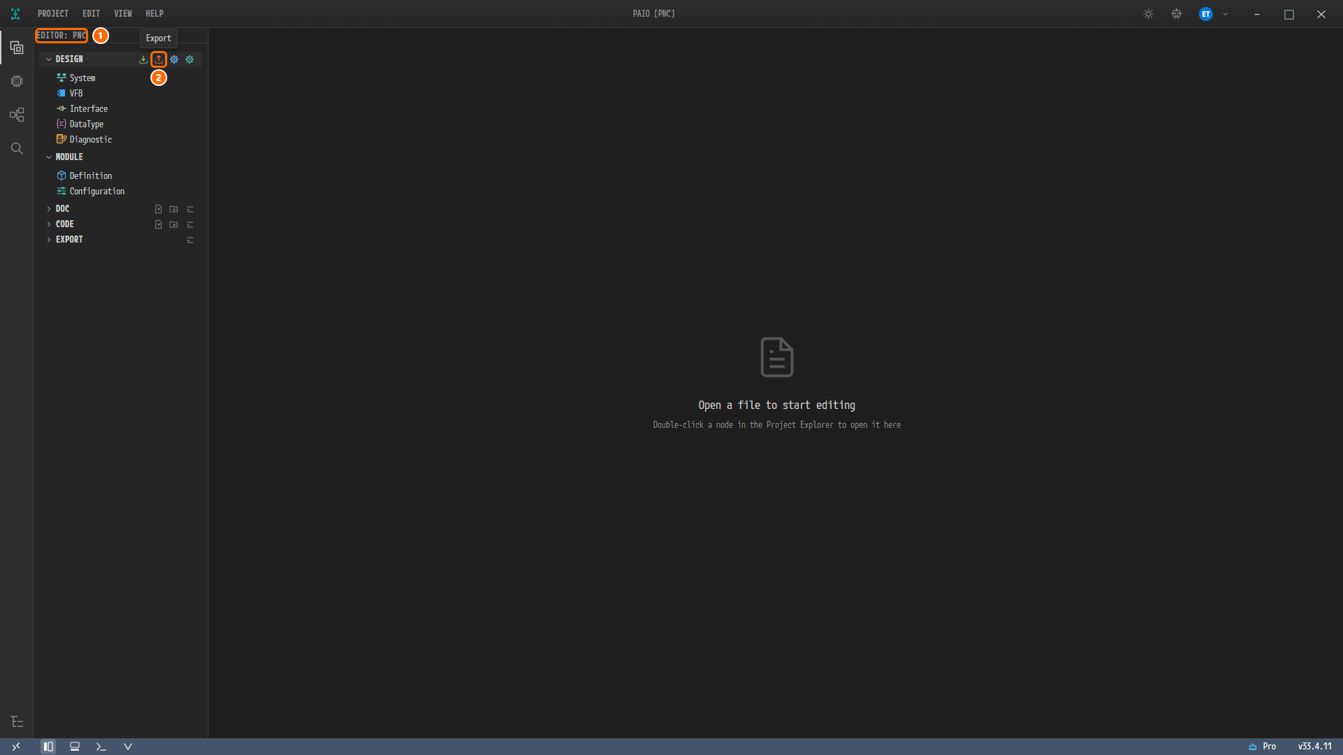
Figure 12-1. The Export icon of the DESIGN header. ① The view header
EDITOR: PNC. ② The icon to click, Export, under the mouse, with its tooltip Export. DESIGN and MODULE are open, and DOC, CODE, and EXPORT are closed. No tab is open, so the editor area on the right showsOpen a file to start editing.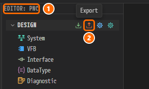
Figure 12-2. A close-up of the same header. ① The view header
EDITOR: PNC. ② Export and its tooltip. The icon to its left is Import, and the two icons to its right are PRTE Code Generation and PARA Code Generation.
Note. Export is also in the menu that opens when you right-click the
designfolder in the Explorer (the Explorer icon at the bottom of the icon bar on the far left). Both run the same export.
-
Click Export. No file picker asks where to save. The result is always created in the project's
exportfolder. -
The Exporting to AUTOSAR progress dialog appears in the middle of the screen. The export finishes in about a second.
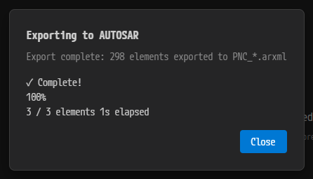
Figure 12-3. The completed Exporting to AUTOSAR dialog. The message reads
Export complete: 298 elements exported to PNC_*.arxml, followed by✓ Complete!,100%,3 / 3 elements 1s elapsed, and the Close button.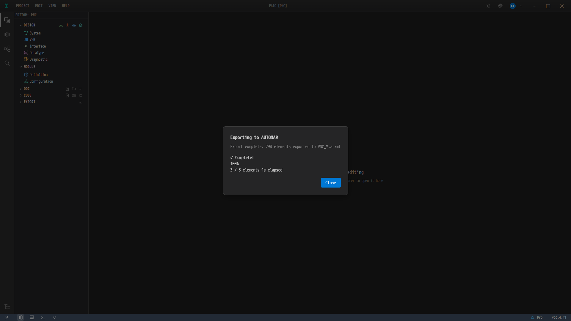
Figure 12-4. The whole window at the moment the export finishes. The progress dialog appears in the middle of the screen and dims everything behind it. No dialog asked for a save location, and the EDITOR view on the left looks exactly as it did before the click.
-
The dialog closes by itself after about two seconds. You can also click Close to dismiss it at once. There is no time to read the dialog slowly, so check the result in the
exportfolder as described in the next section.
Note. The
298 elementsin the message and the3 / 3 elementsin the statistics count different things. The first is the number of exported elements, the second the number of export stages. The two numbers differing is normal. The element count depends on the size of your model, so a number other than298is fine.
Caution. If the export fails,
Export failed: <reason>appears and the dialog stays open.OFFLINE_EXPORT_DENIEDmeans a server connection is required, andPLAN_EXPIREDis a license problem. For the detailed reasons, see Import and Export.
Checking the Generated Files
-
In the EDITOR view on the left, click the EXPORT header to expand it. EXPORT lists the files of the project's
exportfolder. The list refreshes itself when the export finishes, so the five ARXML files are visible right away. File names follow the<project name>_*.arxmlrule, so in this tutorial they all start withPNC_.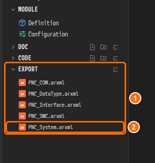
Figure 12-5. The expanded EXPORT section of the EDITOR view. ① EXPORT and the generated ARXML files — in name order, the five files
PNC_COM.arxml,PNC_DataType.arxml,PNC_Interface.arxml,PNC_SWC.arxml, andPNC_System.arxml. ② Among them,PNC_System.arxml, which you open in the next section. -
Each file carries the following PNC-related content.
File PNC-related content PNC_System.arxmlSYSTEM and SYSTEM-MAPPING. Three <PNC-MAPPING>elements (one per PNC), the SYSTEM-level<PNC-VECTOR-LENGTH>/<PNC-VECTOR-OFFSET>, and the SWC-to-ECU mappingPNC_COM.arxmlECU-INSTANCE and MACHINE-DESIGN. The connectors' <PNC-GATEWAY-TYPE>,<PNC-FILTER-ARRAY-MASK>, and<PNC-WAKEUP-CAN-ID>family, the clusters and VLANs, the PNC references on the switch ports, 20<I-SIGNAL-I-PDU-GROUP>elements, the NM settings, and the SOME/IP service instance declarationsPNC_SWC.arxmlThe SWC types and the <PORT-GROUP>elements that represent the VFCs, the machine's three<NM-NETWORK-HANDLE>elements and the FunctionGroup state mapping, the three<NETWORK-HANDLE-PORT-MAPPING>elements of the application AA, and the PARA platform AAs and processesPNC_Interface.arxmlThe port interfaces and service interfaces, including the one <NETWORK-MANAGEMENT-PORT-INTERFACE>used for the PNC requestPNC_DataType.arxmlThe data types used by the interfaces. No PNC-specific element goes in here -
The table below shows which file actually holds how many of each PNC-related element. A
0means the element does not appear in that file.Element COM DataType Interface SWC System PNC-MAPPING0 0 0 0 3 PNC-IDENTIFIER0 0 0 0 3 PNC-VECTOR-LENGTH0 0 0 0 1 PNC-VECTOR-OFFSET0 0 0 0 1 PNC-GATEWAY-TYPE18 0 0 0 0 PNC-FILTER-ARRAY-MASK108 0 0 0 0 PNC-WAKEUP-CAN-ID3 0 0 0 0 I-SIGNAL-I-PDU-GROUP20 0 0 0 0 PROVIDED-SOMEIP-SERVICE-INSTANCE4 0 0 0 0 REQUIRED-SOMEIP-SERVICE-INSTANCE3 0 0 0 0 PORT-GROUP0 0 0 33 0 NM-NETWORK-HANDLE0 0 0 3 0 NETWORK-HANDLE-PORT-MAPPING0 0 0 3 0
Note.
<PNC-VECTOR-LENGTH>and<PNC-VECTOR-OFFSET>appear once on the SYSTEM, not once per PNC. In this example their values are6and2.
Note. The 33
<PORT-GROUP>elements do not mean there are 33 VFCs. There are three VFCs —VFC_Comfort,VFC_ParkAssist, andVFC_Trailer— and these three repeat once for the root compositionPncVehicleand once for every composition and SWC type beneath it, which adds up to 33. All 33 carry<CATEGORY>PARTIAL_NETWORKING</CATEGORY>, and the ones that<PNC-MAPPING>points to are the three directly underPncVehicle.
Note. The table counts opening tags, that is, element declarations. References to those elements from other files (
<...-REF DEST="...">) are not counted. That is why the SOME/IP service instances are counted only inPNC_COM.arxml, where they are declared: inPNC_System.arxmlthey appear only as references such as<SERVICE-INSTANCE-REF DEST="PROVIDED-SOMEIP-SERVICE-INSTANCE">, so the System column reads0.
Note. The counts above come from exporting the finished example. In a project you built by following along, some counts such as
I-SIGNAL-I-PDU-GROUPcome out differently. For which items differ and why, see Appendix — Differences Between Your Project and the Finished Example.
Note. The three
<NM-NETWORK-HANDLE>elements are the ones you created in The AP Machine — NM Handles and FunctionGroup. They are declared inside the machine's<NM-INSTANTIATION>, and that machine is recorded inPNC_SWC.arxml. The three<NETWORK-HANDLE-PORT-MAPPING>elements in the same file point to these handles through<NETWORK-HANDLE-REF DEST="NM-NETWORK-HANDLE">.
Reading PNC-MAPPING in PNC_System.arxml
-
Under EXPORT, double-click PNC_System.arxml. The
PNC:PNC_System.arxmltab opens in the XML editor's view mode. -
Press
Ctrl+Fand type<PNC-MAPPING>in the find box.1 of 3appears and the editor jumps to the first mapping. In the example this isPNC_Comforton line 617.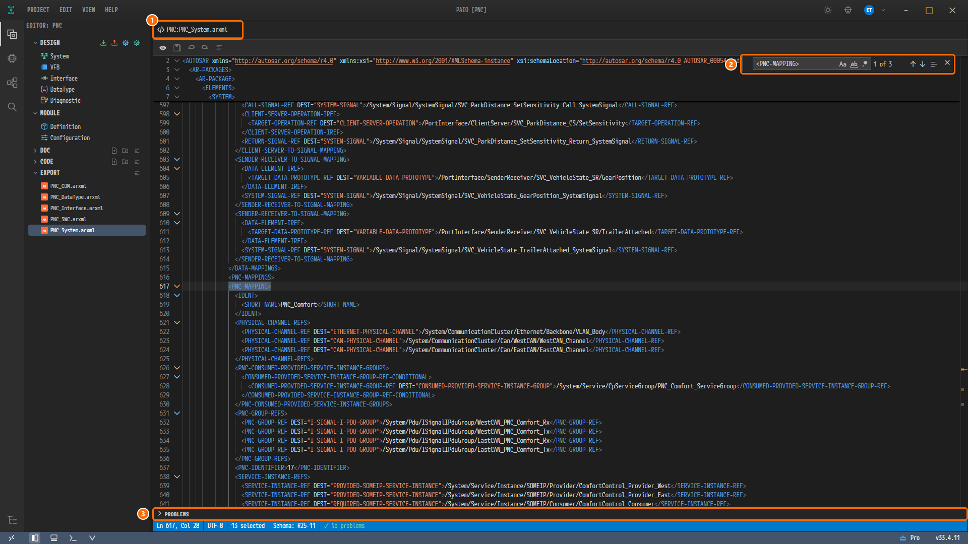
Figure 12-6. The whole window with
PNC_System.arxmlopen. ① The tabPNC:PNC_System.arxml. ② The find box. Typing<PNC-MAPPING>shows1 of 3. ③ The PROBLEMS panel at the bottom. It is collapsed and carries no count badge. The status bar below it readsLn 617, Col 28·UTF-8·13 selected·Schema: R25-11·✓ No problems.13 selectedmeans the 13 characters of the found<PNC-MAPPING>are selected.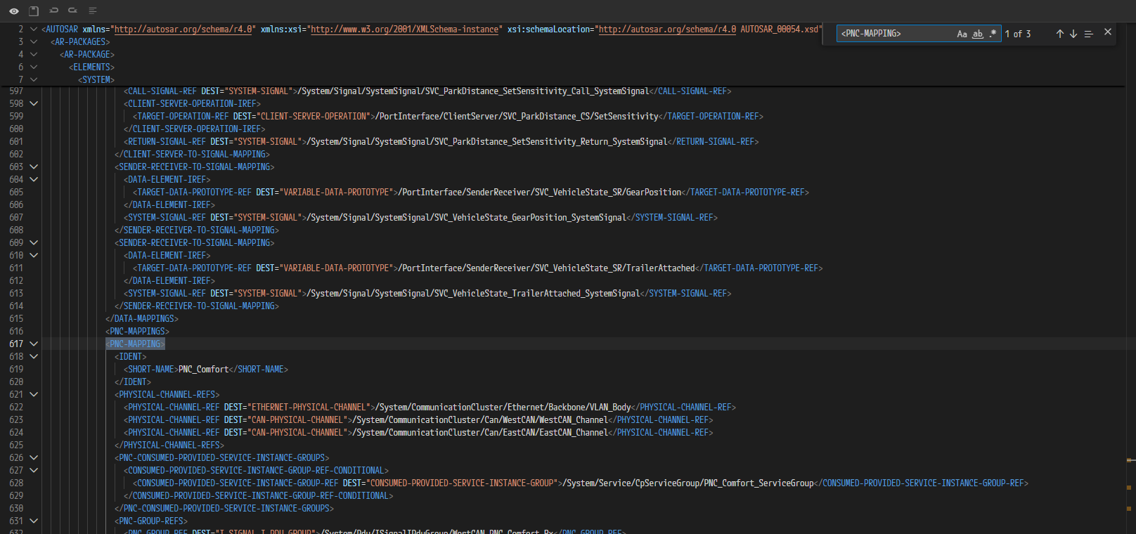
Figure 12-7. A close-up of the first
<PNC-MAPPING>block. It shows the<SHORT-NAME>PNC_Comfort, three physical channel references,PNC-CONSUMED-PROVIDED-SERVICE-INSTANCE-GROUPS, and thePNC-GROUP-REFSthat follow. -
The complete block looks like this. Everything you built in the previous chapters comes together in one place.
<PNC-MAPPING><IDENT><SHORT-NAME>PNC_Comfort</SHORT-NAME></IDENT><PHYSICAL-CHANNEL-REFS><PHYSICAL-CHANNEL-REF DEST="ETHERNET-PHYSICAL-CHANNEL">/System/CommunicationCluster/Ethernet/Backbone/VLAN_Body</PHYSICAL-CHANNEL-REF><PHYSICAL-CHANNEL-REF DEST="CAN-PHYSICAL-CHANNEL">/System/CommunicationCluster/Can/WestCAN/WestCAN_Channel</PHYSICAL-CHANNEL-REF><PHYSICAL-CHANNEL-REF DEST="CAN-PHYSICAL-CHANNEL">/System/CommunicationCluster/Can/EastCAN/EastCAN_Channel</PHYSICAL-CHANNEL-REF></PHYSICAL-CHANNEL-REFS><PNC-CONSUMED-PROVIDED-SERVICE-INSTANCE-GROUPS><CONSUMED-PROVIDED-SERVICE-INSTANCE-GROUP-REF-CONDITIONAL><CONSUMED-PROVIDED-SERVICE-INSTANCE-GROUP-REF DEST="CONSUMED-PROVIDED-SERVICE-INSTANCE-GROUP">/System/Service/CpServiceGroup/PNC_Comfort_ServiceGroup</CONSUMED-PROVIDED-SERVICE-INSTANCE-GROUP-REF></CONSUMED-PROVIDED-SERVICE-INSTANCE-GROUP-REF-CONDITIONAL></PNC-CONSUMED-PROVIDED-SERVICE-INSTANCE-GROUPS><PNC-GROUP-REFS><PNC-GROUP-REF DEST="I-SIGNAL-I-PDU-GROUP">/System/Pdu/ISignalIPduGroup/WestCAN_PNC_Comfort_Rx</PNC-GROUP-REF><PNC-GROUP-REF DEST="I-SIGNAL-I-PDU-GROUP">/System/Pdu/ISignalIPduGroup/WestCAN_PNC_Comfort_Tx</PNC-GROUP-REF><PNC-GROUP-REF DEST="I-SIGNAL-I-PDU-GROUP">/System/Pdu/ISignalIPduGroup/EastCAN_PNC_Comfort_Rx</PNC-GROUP-REF><PNC-GROUP-REF DEST="I-SIGNAL-I-PDU-GROUP">/System/Pdu/ISignalIPduGroup/EastCAN_PNC_Comfort_Tx</PNC-GROUP-REF></PNC-GROUP-REFS><PNC-IDENTIFIER>17</PNC-IDENTIFIER><SERVICE-INSTANCE-REFS><SERVICE-INSTANCE-REF DEST="PROVIDED-SOMEIP-SERVICE-INSTANCE">/System/Service/Instance/SOMEIP/Provider/ComfortControl_Provider_West</SERVICE-INSTANCE-REF><SERVICE-INSTANCE-REF DEST="PROVIDED-SOMEIP-SERVICE-INSTANCE">/System/Service/Instance/SOMEIP/Provider/ComfortControl_Provider_East</SERVICE-INSTANCE-REF><SERVICE-INSTANCE-REF DEST="REQUIRED-SOMEIP-SERVICE-INSTANCE">/System/Service/Instance/SOMEIP/Consumer/ComfortControl_Consumer</SERVICE-INSTANCE-REF></SERVICE-INSTANCE-REFS><SHORT-LABEL>PNC_Comfort</SHORT-LABEL><VFC-IREFS><VFC-IREF><CONTEXT-COMPOSITION-REF DEST="ROOT-SW-COMPOSITION-PROTOTYPE">/System/PncVehicle/PncVehicle</CONTEXT-COMPOSITION-REF><TARGET-REF DEST="PORT-GROUP">/SwComponentType/Composition/PncVehicle/VFC_Comfort</TARGET-REF></VFC-IREF></VFC-IREFS><WAKEUP-FRAME-REFS><WAKEUP-FRAME-REF DEST="CAN-FRAME-TRIGGERING">/System/CommunicationCluster/Can/WestCAN/WestCAN_Channel/FT_WestCAN_NmFrame_DoorCtrl_FL</WAKEUP-FRAME-REF><WAKEUP-FRAME-REF DEST="CAN-FRAME-TRIGGERING">/System/CommunicationCluster/Can/EastCAN/EastCAN_Channel/FT_EastCAN_NmFrame_DoorCtrl_FR</WAKEUP-FRAME-REF></WAKEUP-FRAME-REFS></PNC-MAPPING> -
Match each element against the chapter that created it.
Element Value Chapter that created it PHYSICAL-CHANNEL-REFSVLAN_Body,WestCAN_Channel,EastCAN_ChannelTopology Design PNC-IDENTIFIER17PNC Definition and Connector PNC Properties PNC-GROUP-REFSFour I-PDU Groups Signals, PDUs, Frames, and I-PDU Groups SERVICE-INSTANCE-REFSThree SOME/IP instances Interfaces and SOME/IP Services VFC-IREFSVFC_Comfort(PORT-GROUP)VFB and VFC WAKEUP-FRAME-REFSFT_WestCAN_NmFrame_DoorCtrl_FL,FT_EastCAN_NmFrame_DoorCtrl_FRSignals, PDUs, Frames, and I-PDU Groups
Note. The
PNC_Comfort_ServiceGroupthatPNC-CONSUMED-PROVIDED-SERVICE-INSTANCE-GROUPSpoints to is not something you created on screen. PAIO creates a service discovery start/stop group for each PNC automatically during export.
Note.
SHORT-LABELand theSHORT-NAMEinsideIDENTare bothPNC_Comfort. You can step through the other two PNCs (PNC_ParkAssistandPNC_Trailer) with the ↓ button in the find box.
Checking the Schema Check Results
The XML editor checks the file once against the bundled AUTOSAR XSD when it opens the file. There is no run button.
-
Click the PROBLEMS header below the editor to expand the panel. When there are zero errors, the header shows no count badge and the panel does not expand by itself.
-
Confirm that the table contains only
No problems found, and that the status bar showsSchema: R25-11and✓ No problems.
Figure 12-8. The expanded PROBLEMS panel. The columns are # / LINE / ELEMENT / ERROR TYPE / DESCRIPTION / SUGGESTION, and the only content is
No problems found. The status bar below showsSchema: R25-11and✓ No problems. -
Open the remaining four files the same way, by double-clicking each one under EXPORT, and check them. In the finished example,
PNC_DataType.arxml,PNC_Interface.arxml, andPNC_SWC.arxmlreport zero errors likePNC_System.arxml.PNC_COM.arxmlreports 22 errors: its PROBLEMS panel expands by itself with the count badge22, and the status bar shows22 errorsin place of✓ No problems.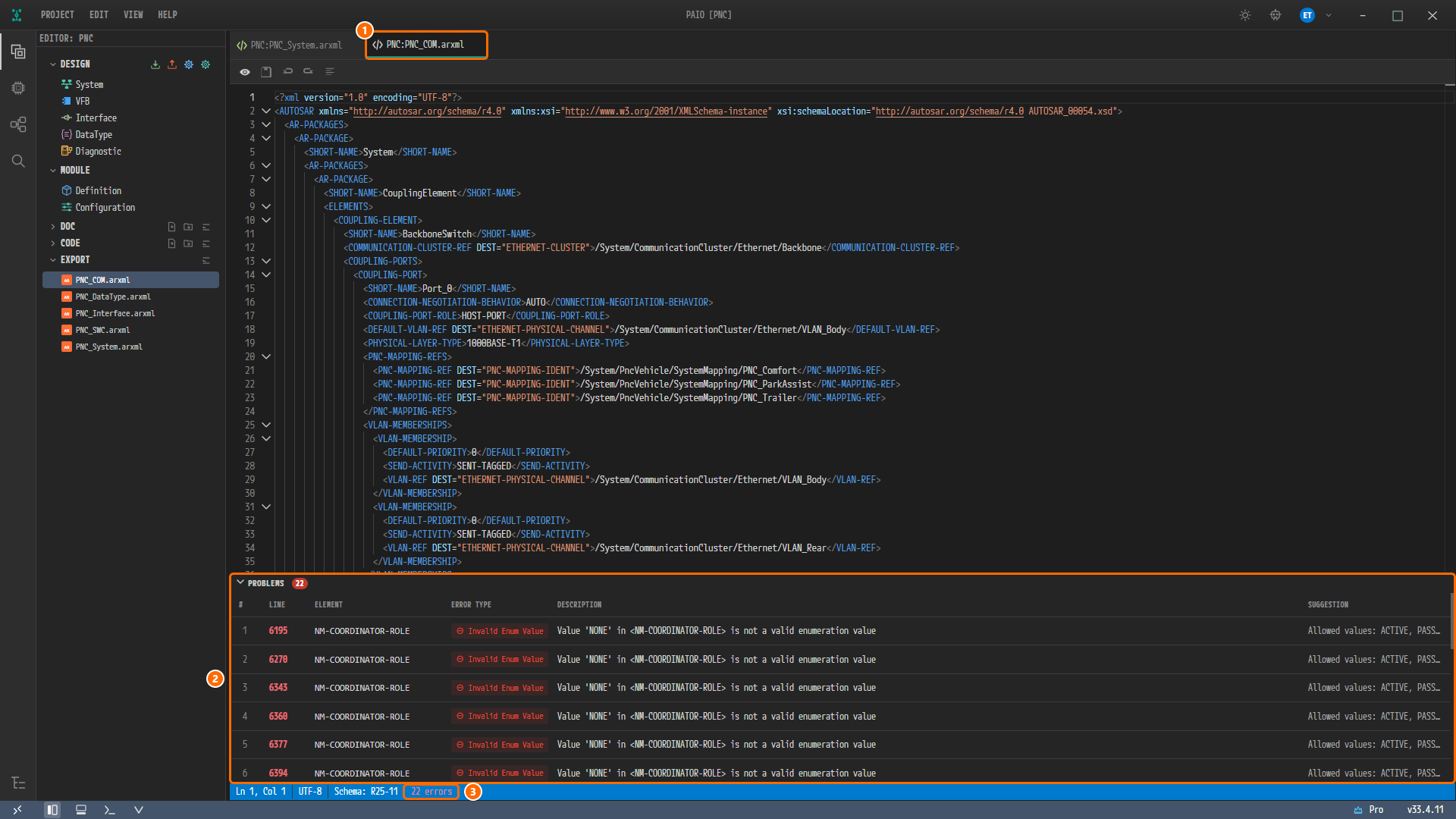
Figure 12-9.
PNC_COM.arxmlright after it opens. ① The tabPNC:PNC_COM.arxml. ② The PROBLEMS panel, expanded by itself, with the count badge22. The first rows areInvalid Enum Valueerrors onNM-COORDINATOR-ROLE:Value 'NONE' in <NM-COORDINATOR-ROLE> is not a valid enumeration value, with the suggestionAllowed values: ACTIVE, PASSIVE, which the SUGGESTION column cuts short. ③22 errorsat the end of the status bar, afterSchema: R25-11.
Note. The errors in
PNC_COM.arxmlcome from how the current PAIO export writes two kinds of values that the R25-11 schema does not accept. In the finished example there are 22. Twelve areInvalid Enum Valueerrors: the NM nodes whose NM COORDINATOR ROLE is NONE (NM Configuration) are written as<NM-COORDINATOR-ROLE>NONE</NM-COORDINATOR-ROLE>, while the schema allows onlyACTIVEandPASSIVE. The other ten areInvalid Valueerrors: in the five<SOMEIP-SD-SERVER-SERVICE-INSTANCE-CONFIG>elements, the<MAX-VALUE>and<MIN-VALUE>of<REQUEST-RESPONSE-DELAY>are written as the textundefined, where the schema expects a number (Value must be an xsd:double). The other four files are not affected.
Note. The schema check and the VALIDATION panel from The System Editor and Validation are two different checks. The schema check looks at whether the ARXML document matches the AUTOSAR XSD grammar, while the validation panel looks at whether the model obeys the AUTOSAR constraints (
constr_*). Both must be at zero before another tool can use this ARXML as it is.
Verifying by Importing Again
You can read the exported ARXML back in as it is. Checking whether you arrive at the same model is a round-trip check. This section is optional.
- Create an empty project. This lets you keep the original project and compare against it. PROJECT › New Project... (or New Project on the Welcome tab, which HELP › Welcome opens) will do. The new project opens in a window of its own, and the window of
PNCcloses. - In the EDITOR view of the new window, click Import, the first of the four icons on the right of the DESIGN header. The file picker
Select files to importopens. - Select all five ARXML files in
PNC/export. You can pick several at once. - The Importing ARXML Files progress dialog appears and runs through
parsing→merging→resolving. - When the import finishes, click System under DESIGN in the EDITOR view to open the System editor, and confirm that the three PNCs, the identifiers
17/18/19, and the connectors' PNC GATEWAY TYPE are unchanged.
Caution. Importing into the same project is handled as a merge, not an overwrite, and if any item has a different value, the Conflict Resolution dialog appears. When the import starts, unsaved edits in every open tab are written to disk first. For the detailed behavior, see Import and Export.
Why Is the Output Split into Five Files?
PAIO does not export a project as one block of ARXML. It splits the output according to the roles of the AUTOSAR documents. Data types and interfaces are definitions that several projects share, SWC is the software structure, COM is the ECU and network deployment, and System is the mapping that ties the two together. The PNC design appears scattered across several files for the same reason. "Which PNC binds which channels, PDU groups, service instances, and VFCs" is a mapping, so it goes into System, while "whether this connector is a gateway and what its filter mask is" is ECU deployment, so it goes into COM. As a result, another tool can read only the documents it needs.
Check Your Work
- EXPORT in the EDITOR view lists the five files
PNC_COM.arxml,PNC_DataType.arxml,PNC_Interface.arxml,PNC_SWC.arxml, andPNC_System.arxml. - Searching for
<PNC-MAPPING>inPNC_System.arxmlshows1 of 3. - The
<SHORT-NAME>of the first mapping isPNC_Comfortand its<PNC-IDENTIFIER>is17. - The same block holds three physical channel references, four
PNC-GROUP-REFelements, threeSERVICE-INSTANCE-REFelements, oneVFC-IREF, and twoWAKEUP-FRAME-REFelements. - The status bar of
PNC_System.arxmlshowsSchema: R25-11and✓ No problems, and the PROBLEMS table contains onlyNo problems found. - Opening the remaining four files shows zero errors in
PNC_DataType.arxml,PNC_Interface.arxml, andPNC_SWC.arxml, and inPNC_COM.arxmlonly the errors that come from the export (22 in the finished example: 12 onNM-COORDINATOR-ROLE, 5 onMAX-VALUE, and 5 onMIN-VALUE).
Next Steps
The Appendix summarizes the file structure of the project this tutorial built and what each model file contains.