Topology — the Ethernet Connector and Endpoints
What You Will Do
In this chapter you build the network topology on the HPC node Ecu that you configured in Configuring the Machine.
In the System editor you create the Ethernet controller Ecu_EthernetController and the Ethernet connector eth0 on the node Ecu, then use the connector's + badge to create the communication cluster EthernetCluster and attach the connector to its physical channel PhysicalChannel.
Next, in the NETWORK ENDPOINT section of the connector eth0 you enter the unicast address 127.0.0.1 and the multicast address 224.0.0.1 with port 30490 for SOME/IP service discovery, and in APPLICATION ENDPOINTS you add the three UDP ports 20001, 20002 and 20003.
When you finish this chapter, the controller, connector, cluster and endpoints are saved in design/IVC.io.model, Network Management stays off for the new cluster, and the VALIDATION panel shows No validation issues. as before. The later chapters SOME/IP Deployment and Service Instances and Binding Service Instances to the Connector use this connector and these UDP ports.
Before You Begin
- Start from the state at the end of Configuring the Machine. The title bar reads
PAIO [AADesign], the System editor canvas holds only the HPC nodeEcu(no controller, connector or cluster), and the VALIDATION panel showsNo validation issues.. - You may close the tab
AADesign:VFBleft open from chapter 2. This chapter starts by opening System from DESIGN in the EDITOR view.
The values you type in this chapter are listed below. The channel name PhysicalChannel is the default that is attached automatically when the cluster is created, so you do not type it.
| Where | Item | Value |
|---|---|---|
| ETHERNET CONTROLLER panel | NAME | Ecu_EthernetController |
| ETHERNET CONNECTOR panel | NAME | eth0 |
| ETHERNET CONNECTOR panel | CONTROLLER | Select Ecu_EthernetController from the list |
| ETHERNET CLUSTER panel | NAME | EthernetCluster |
| ETHERNET CLUSTER panel | PHYSICAL CHANNELS › CHANNEL NAME | PhysicalChannel (default, leave as is) |
| NETWORK ENDPOINT | UNICAST IPV4 ADDRESS | 127.0.0.1 |
| NETWORK ENDPOINT | ADDRESS SOURCE | Click FIXED |
| NETWORK ENDPOINT › MULTICAST CONFIG | MULTICAST IPV4 ADDRESS | 224.0.0.1 |
| NETWORK ENDPOINT › MULTICAST CONFIG | MULTICAST PORT | 30490 |
| APPLICATION ENDPOINTS | Three cards, TYPE = UDP, PORT NUMBER | 20001, 20002, 20003 |
| Communication Cluster Configuration dialog | NM CLUSTER, TIME DOMAIN tabs | Disabled (default, leave as is) |
Note. An input field in the properties panel commits its value only when you leave the field. In this chapter you press the
Tabkey after typing to commit. Segment buttons such as FIXED and UDP commit as soon as you click them.
Opening the System Editor
- In the EDITOR view on the left, click System under DESIGN. The tab
AADesign:Systemopens, withSystemat the top left of the canvas and the HPC nodeEcuin the middle.
The node header reads Ecu [HPC]; the name in brackets is the composition HPC mapped onto the node in Creating the Project and the HPC Machine.
Creating the Ethernet Controller
Adding the Controller
-
Right-click the empty body of the node
Ecu. The menu shows Add Connector, Add Controller, Add Ethernet Switch, Add Gateway, SW Mapping, Extract Machine and Delete. -
Hover over Add Controller and click Ethernet in the submenu.
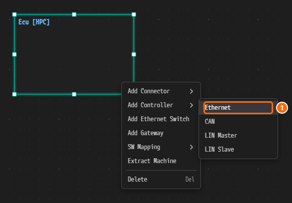
Figure 3-1. The right-click menu of the node
Ecu. The submenu of Add Controller is Ethernet, CAN, LIN Master and LIN Slave; click ① Ethernet. -
A small square with a green border appears inside the node. This is the controller, and its default name is
Ecu_Ethernet_Controller_0.
Renaming the Controller
-
Click the green square. The ETHERNET CONTROLLER panel opens on the right.
-
Change the value of the NAME field to
Ecu_EthernetControllerand press theTabkey.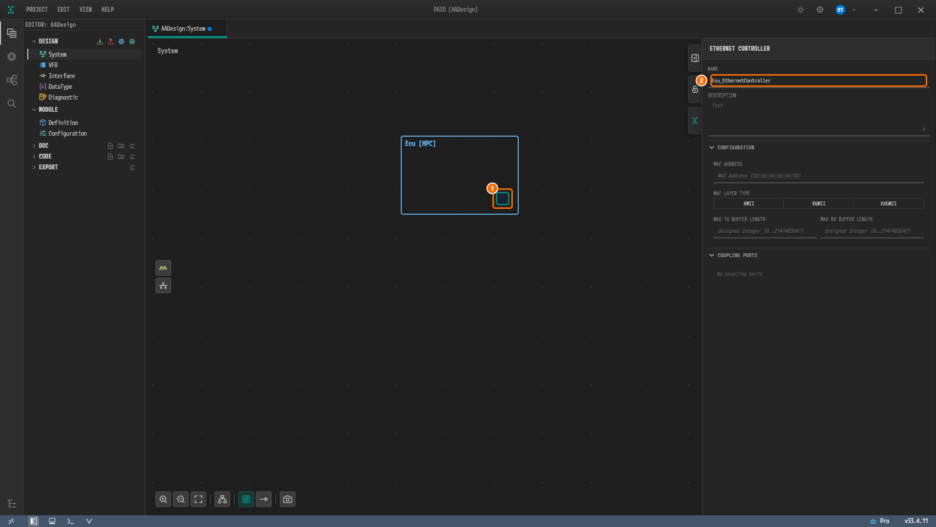
Figure 3-2. The System editor with the controller selected. ① The green square (controller) inside the node, ② NAME =
Ecu_EthernetController. DESCRIPTION is empty, and MAC ADDRESS, MAC LAYER TYPE, MAX TX BUFFER LENGTH and MAX RX BUFFER LENGTH under CONFIGURATION as well as COUPLING PORTS are all left empty. The tabAADesign:Systemcarries the modified marker ●.
NAME is the only value you change in this panel. Leave XMII, XGMII and XXGMII under MAC LAYER TYPE unselected, and leave COUPLING PORTS at No coupling ports. The square on the canvas shows no name, so check the name in the panel.
Creating the Ethernet Connector
Adding the Connector
-
Right-click the empty body of the node
Ecuagain. -
Hover over Add Connector and click Ethernet in the submenu.
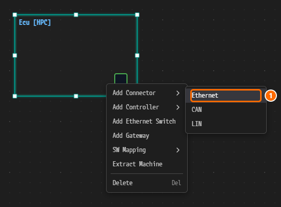
Figure 3-3. Add Connector in the same menu. The submenu is Ethernet, CAN and LIN; click ① Ethernet. The controller you just created is visible inside the node.
-
A blue square appears on the bottom border of the node, with a green + badge below it. This blue square is the connector, and its default name is
Ecu_Ethernet_Connector_0.
Renaming the Connector and Choosing the Controller
-
Click the blue square. The ETHERNET CONNECTOR panel opens on the right.
-
Change the value of the NAME field to
eth0and press theTabkey. -
Open the CONTROLLER combo (initially
Select controller...) and clickEcu_EthernetController. The list contains only the one Ethernet controller of this node.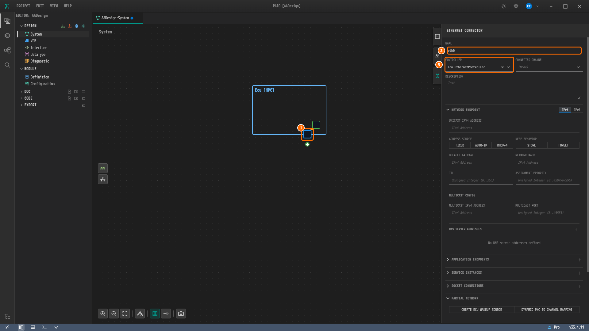
Figure 3-4. The System editor with the connector selected. ① The blue square (connector) on the bottom border of the node and the + badge below it, ② NAME =
eth0, ③ CONTROLLER =Ecu_EthernetController. CONNECTED CHANNEL is still(None), and the IPv4 fields of NETWORK ENDPOINT are all empty.
Caution. A connector is not attached to a controller automatically. If you do not choose a CONTROLLER, the connector in the ARXML export has no controller reference. Be sure to choose
Ecu_EthernetControllerfrom the list.
The panel has the sections NETWORK ENDPOINT (expanded, with an IPv4 / IPv6 toggle at the right of the header), APPLICATION ENDPOINTS (collapsed, +), SERVICE INSTANCES (collapsed, +) and further sections below them. This chapter uses only NETWORK ENDPOINT and APPLICATION ENDPOINTS. SERVICE INSTANCES is used in Binding Service Instances to the Connector, and the remaining sections are not used in this tutorial.
Creating the Communication Cluster
The cluster is created from the + badge below the connector, not from a canvas menu.
Adding the Cluster
-
Click the green + badge below the connector. A menu with a single item opens.
-
Click Create CommunicationCluster [Ethernet].

Figure 3-5. The + badge menu of the connector. Click ① Create CommunicationCluster [Ethernet]. The short orange line between the controller and the connector is the controller reference you chose in step 3.
-
A small blue square (the cluster) appears below the node with its name written under it, and a blue line connects the connector and the cluster. Its default name is
EthernetCluster_0; the physical channelPhysicalChannelis created automatically and the connectorEcu/eth0is attached to that channel automatically.
Renaming the Cluster
-
Click the cluster square. The ETHERNET CLUSTER panel opens on the right.
-
Change the value of the NAME field to
EthernetClusterand press theTabkey. The name under the square changes toEthernetCluster.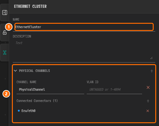
Figure 3-6. The ETHERNET CLUSTER panel. ① NAME =
EthernetCluster, ② the PHYSICAL CHANNELS section. The single channel row has CHANNEL NAMEPhysicalChanneland an empty VLAN ID (hintUNTAGGED or 1-4094), and Connected Connectors (1) listsEcu/eth0.
Do not change CHANNEL NAME or VLAN ID. The Ethernet cluster panel has no protocol or baud rate section.
Network Endpoint — Unicast and Multicast
In the NETWORK ENDPOINT section of the connector eth0, enter the unicast address and the multicast address and port for SOME/IP service discovery.
-
Click the connector
eth0(the blue square on the bottom border of the node) again. CONNECTED CHANNEL in the ETHERNET CONNECTOR panel is now filled withEthernetCluster / PhysicalChannel. -
Check that the toggle at the right of the NETWORK ENDPOINT header is IPv4.
-
Type
127.0.0.1into the UNICAST IPV4 ADDRESS field (hintIPv4 Address) and press theTabkey. -
Click FIXED in the ADDRESS SOURCE segment. On a new connector none of FIXED, AUTO-IP and DHCPv4 is selected.
-
Type
224.0.0.1into MULTICAST IPV4 ADDRESS under MULTICAST CONFIG and press theTabkey. -
Type
30490into MULTICAST PORT (hintUnsigned Integer (0..65535)) and press theTabkey.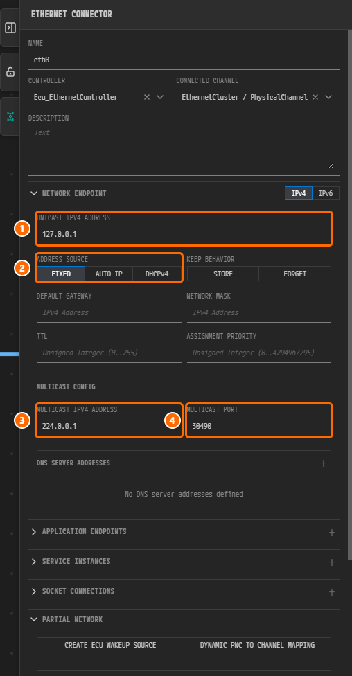
Figure 3-7. The NETWORK ENDPOINT section after entering the values. ① UNICAST IPV4 ADDRESS =
127.0.0.1, ② ADDRESS SOURCE = FIXED, ③ MULTICAST IPV4 ADDRESS =224.0.0.1, ④ MULTICAST PORT =30490. KEEP BEHAVIOR, DEFAULT GATEWAY, NETWORK MASK, TTL and ASSIGNMENT PRIORITY are empty, and DNS SERVER ADDRESSES readsNo DNS server addresses defined.
Leave KEEP BEHAVIOR (STORE / FORGET), DEFAULT GATEWAY, NETWORK MASK, TTL, ASSIGNMENT PRIORITY and DNS SERVER ADDRESSES empty. The IPv6 toggle is not used.
Caution. Be sure to click FIXED under ADDRESS SOURCE. If you do not, no address assignment method is saved for the unicast endpoint.
Application Endpoints — Three UDP Ports
In the APPLICATION ENDPOINTS section of the same panel, add the UDP ports 20001, 20002 and 20003. The first port is shown as a procedure; repeat the same steps for the other two.
Adding the First Endpoint
- Click the NETWORK ENDPOINT header to collapse the section. This only shortens the screen and does not affect any value.
- Click the APPLICATION ENDPOINTS header to expand the section. At first it reads
No application endpoints defined. - Click the + button at the right of the header (tooltip
Add Application Endpoint). One card appears with the summary lineTCP eth0, 127.0.0.1:0. A new endpoint always starts as TCP with port0. - Click the summary line of the card to expand it. You see the TYPE segment (TCP / UDP), PORT NUMBER (value
0), and the TCP-only fields KEEP ALIVES, NAGLES ALGORITHM, KEEP ALIVE TIME, KEEP ALIVE INTERVAL, KEEP ALIVE PROBES and RECEIVE WINDOW MIN. - Click UDP under TYPE. The badge on the summary line changes to
UDPat once, and the card stays expanded: the TCP-only fields disappear and only TYPE and PORT NUMBER remain. - Type
20001into PORT NUMBER and press theTabkey. The summary line changes toUDP eth0, 127.0.0.1:20001.
Adding the Remaining Endpoints
Repeat steps 3 to 6 above twice more. Only the values differ.
| Order | TYPE | PORT NUMBER | Summary line | Name assigned automatically |
|---|---|---|---|---|
| 1 | UDP | 20001 | UDP eth0, 127.0.0.1:20001 | Ecu_eth0_UDP_20001 |
| 2 | UDP | 20002 | UDP eth0, 127.0.0.1:20002 | Ecu_eth0_UDP_20002 |
| 3 | UDP | 20003 | UDP eth0, 127.0.0.1:20003 | Ecu_eth0_UDP_20003 |
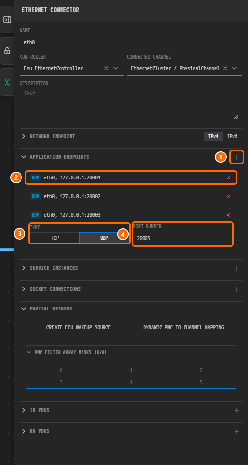
Figure 3-8. The APPLICATION ENDPOINTS section after adding the three endpoints. ① The + button at the right of the header, ② the summary line of the first card, UDP eth0, 127.0.0.1:20001, ③ the TYPE toggle of the expanded third card (UDP selected), ④ PORT NUMBER = 20003. Each card has a × on the right for deletion.
The endpoint name has no input field; it is assigned automatically by the rule {node}_{connector}_{UDP|TCP}_{port}. The order in which you set TYPE and PORT NUMBER does not matter, and the resulting name is the same. Do not create any TCP endpoint.
Saving
-
Click an empty spot on the canvas to clear the selection. The properties panel closes.
-
Press
Ctrl+S. The modified marker ● on the tabAADesign:Systemdisappears anddesign/IVC.io.modelis saved.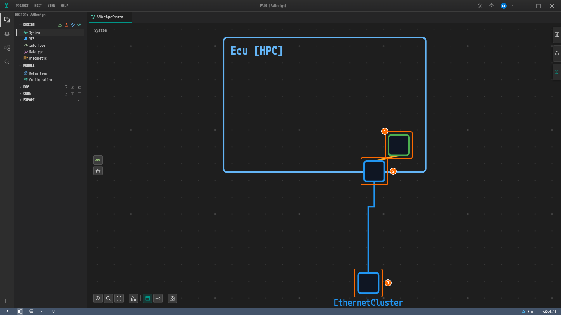
Figure 3-9. The System editor canvas after saving. ① The green square inside the node
Ecu(controllerEcu_EthernetController), ② the blue square on the bottom border (connectoreth0), ③ the blue square below (clusterEthernetCluster), with the nameEthernetClusterunder it. The blue line between the connector and the cluster is thePhysicalChannelconnection, and the short orange line between the controller and the connector is the controller reference. The V icon in the footer carries no badge.
Note.
Ctrl+Ssavesdesign/IVC.io.modelwhen the System editor has focus, so click the canvas first. The controller and connector squares show no names; click a square and check its name in the panel. Only the cluster square has its name written under it.
Checking the Validation Result and the NM Cluster Tab
Saving the topology raises no validation finding. Network Management (NM) is off for a new cluster and is turned on per cluster in the cluster dialog, so EthernetCluster gets no UDP NM cluster and there are no NM timing values to fill in. In this section you check the VALIDATION panel and the NM CLUSTER tab of the cluster dialog.
Checking the Validation Result
-
Look at the V icon in the footer at the bottom of the window, the fifth icon from the left. It carries no badge.
-
Look at the VALIDATION panel. If it is closed, click the V icon in the footer. The header carries no badge, and the panel reads
No validation issues.under the columns ELEMENT TYPE, NAME, DESCRIPTION and CONSTR.
Figure 3-10. The VALIDATION panel right after saving the topology. The header has no badge and the body is the single line
No validation issues..
The validation result is zero findings, the same as at the end of Configuring the Machine. design/IVC.io.model now holds the controller, the connector with its endpoints and the cluster, but no Network Management settings.
Checking the NM CLUSTER Tab in the Dialog
-
Double-click the cluster square on the canvas. If the VALIDATION panel covers it, first click the V icon in the footer to close the panel. A dialog titled Communication Cluster Configuration [EthernetCluster] opens with the tabs CLUSTER, NM CLUSTER and TIME DOMAIN, showing the CLUSTER tab first.
-
Click the NM CLUSTER tab. The hollow dot in front of the tab name means that NM is off for this cluster, and the tab shows the NM editor only as a dimmed preview that takes no input.
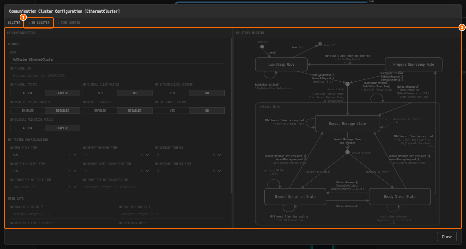
Figure 3-11. The Communication Cluster Configuration [EthernetCluster] dialog on the NM CLUSTER tab. ① The NM CLUSTER tab with a hollow dot in front of its name, ② the dimmed preview of NM CONFIGURATION and NM STATE MACHINE, which takes no input.
-
Click the Close button at the bottom right. No save confirmation appears.
While NM is off, the values in the preview are not stored in the design. CHANNEL in NM CONFIGURATION on the left shows NAME NmCluster_EthernetCluster, and NM TIMING CONFIGURATION shows NM MSG CYCLE TIME 0.5, NM REPEAT MESSAGE TIME 1, NM NETWORK TIMEOUT 2, NM WAIT BUS SLEEP TIME 1.5, NM REMOTE SLEEP INDICATION TIME 1 and NM MESSAGE TIMEOUT TIME 2 (all in s). TIME DOMAIN carries the same hollow dot. The CLUSTER and TIME DOMAIN tabs are not used.
Caution. Do not choose Enable. Hovering over the NM CLUSTER tab shows the tooltip
Disabled. Right-click to enable., and right-clicking the tab opens a menu with the single item Enable, which turns NM on for this cluster. The reference design has no NM settings, so this tutorial leaves NM off.
Checking the Validation Result Again
- Look at the VALIDATION panel. If it is closed, click the V icon in the footer. It still shows
No validation issues..
Closing the dialog without choosing Enable leaves the design as it was, so the controller, connector, cluster and endpoints you created earlier remain as they are.
Why Is It Designed This Way?
- The connector is named
eth0, and the cluster and channel areEthernetCluster/PhysicalChannel. These match the names of the Ethernet connector, cluster and physical channel in the reference design. The channel has no VLAN, so VLAN ID is left empty. - The controller is not in the reference design, but you create one. The connector
eth0of the reference design has no controller reference. In the System editor, however, attaching a connector to a controller is the natural way, so you create and chooseEcu_EthernetController. In ARXML Export,ETHERNET-COMMUNICATION-CONTROLLER Ecu_EthernetControllerappears as an element added over the reference design, and the connectoreth0carries aCOMM-CONTROLLER-REF. - The SOME/IP service discovery port
30490comes from the connector's multicast port. The panel of the HPC node has no field for the SD port. TheSOMEIP-SERVICE-DISCOVERY-PORT 30490and the multicast SD address reference in the export are built from MULTICAST IPV4 ADDRESS224.0.0.1and MULTICAST PORT30490of the connectoreth0. - TTL and ASSIGNMENT PRIORITY are left empty. The multicast network endpoint of the reference design has
TTL 0andASSIGNMENT-PRIORITY 0; the exporter writes these two values as the constant0for the multicast endpoint, so the result matches the reference design without any input. - There are three UDP ports,
20001,20002and20003, and no TCP port. The automatically assigned endpoint names such asEcu_eth0_UDP_20001match theAP-APPLICATION-ENDPOINTnames of the reference design. In Binding Service Instances to the Connector, the consumerActuator_Sensoris bound to20001,Fusion_Sensorto20002and the providerProvider_Sensorto20003. - Network Management stays off. The reference design contains no Network Management elements at all. NM is turned on per cluster with Enable on the NM CLUSTER tab and is off for a new cluster, so you leave it off:
EthernetClustergets no UDP NM cluster, anddesign/IVC.io.modelholds no NM settings.
Check
- The System editor canvas shows the green square (controller) inside the node
Ecu, the blue square (connector) on its bottom border, the blue square (cluster) below with the nameEthernetClusterunder it, and the blue line connecting the latter two. - Clicking the controller shows NAME =
Ecu_EthernetControllerin the ETHERNET CONTROLLER panel. - Clicking the connector shows NAME =
eth0, CONTROLLER =Ecu_EthernetControllerand CONNECTED CHANNEL =EthernetCluster / PhysicalChannelin the ETHERNET CONNECTOR panel. - Under NETWORK ENDPOINT, UNICAST IPV4 ADDRESS is
127.0.0.1, ADDRESS SOURCE is FIXED, MULTICAST IPV4 ADDRESS is224.0.0.1and MULTICAST PORT is30490. - APPLICATION ENDPOINTS holds the three cards
UDP eth0, 127.0.0.1:20001,UDP eth0, 127.0.0.1:20002andUDP eth0, 127.0.0.1:20003, and no TCP card. - Clicking the cluster shows NAME =
EthernetCluster, CHANNEL NAME =PhysicalChannelandEcu/eth0under Connected Connectors (1) in the ETHERNET CLUSTER panel. - In Communication Cluster Configuration [EthernetCluster], the tabs NM CLUSTER and TIME DOMAIN have a hollow dot in front of their names.
- The tab
AADesign:Systemcarries no modified marker ●. - The VALIDATION panel shows
No validation issues.and the header has no badge.
Next Step
In Data Types you use the DataType editor to create the C++ implementation data types ByteArray and String that the service interface will use.