Service Instance Mapping
What You Will Do
In this chapter you double-click Sensor, Fusion and Actuator inside the composition HPC one after another to open the AA Internal Behavior dialog, right-click the body on the canvas and create a mapping box with Add Instance › ara::com › Service Instance. Then you pick PORT and SERVICE INSTANCE in the SERVICE INSTANCE MAPPING panel on the right. The P port of Sensor is mapped to the provider instance Provider_Sensor; the R ports of Fusion and Actuator are mapped to the consumer instances Fusion_Sensor and Actuator_Sensor. On the two consumers you enter 2 and 1 as the CLIENT ID. Sensor is shown as a procedure, Fusion shows only the part where the CLIENT ID is added, and Actuator is repeated from a table.
When you finish this chapter, Sensor.swc.io.model, Fusion.swc.io.model and Actuator.swc.io.model each hold one entry in service-instance-mappings. In ARXML Export these become the reference design's three SERVICE-INSTANCE-TO-PORT-PROTOTYPE-MAPPING elements Sensor_AA_Sensor, Fusion_AA_Sensor and Actuator_AA_Sensor.
Before You Begin
- Start from the state at the end of Executables and Processes. The five files in
design/SWC/AdaptiveApplication/haveports,executableandprocess, and noservice-instance-mappingsyet. - The service instances created in SOME/IP Deployment and Service Instances —
Provider_Sensor(provider, Instance ID1),Fusion_SensorandActuator_Sensor(consumers, Required Instance IDANY) — are inSERVICE.io.model. All three are instances of the serviceSensor. - In Binding Service Instances to the Connector you bound the three instances to the UDP ports
20003,20002and20001of the connectoreth0. The read-back block of this chapter shows those endpoints as they are. - The VALIDATION panel shows
No validation issues.. - Only the three with ports —
Sensor,FusionandActuator— are mapped.CMandEMhave no ports and are not opened in this chapter.
The only things you type on the keyboard in this chapter are the two CLIENT ID values (2 and 1). Everything else is a right-click, a mouse hover, a click, a dropdown pick, Ctrl+S or Close. The name of the mapping box and the saved name are chosen by the product, not by you.
Sensor | Fusion | Actuator | |
|---|---|---|---|
| PORT | Sensor (P) | Sensor (R) | Sensor (R) |
| SERVICE INSTANCE | Provider_Sensor (SOME/IP) | Fusion_Sensor (SOME/IP) | Actuator_Sensor (SOME/IP) |
| CLIENT ID | no field | 2 → 0x2 | 1 → 0x1 |
| Mapping box / INSTANCE SPECIFIER | Sensor/AA/Sensor | Fusion/AA/Sensor | Actuator/AA/Sensor |
| PROCESS (automatic) | Sensor | Fusion | Actuator |
| Read-back SERVICE ID / VERSION | 0x000B / 1.0 | same | same |
| Read-back INSTANCE ID | 0x0001 | 0xFFFF | 0xFFFF |
| Read-back ENDPOINT | 127.0.0.1:20003 | 127.0.0.1:20002 | 127.0.0.1:20001 |
| Saved name (automatic) | Sensor_AA_Sensor | Fusion_AA_Sensor | Actuator_AA_Sensor |
The three Adaptive Applications are independent of each other, so any order works. This chapter does the provider Sensor first and the consumers Fusion and Actuator afterwards.
Mapping the Port of Sensor to Provider_Sensor
Opening the AA Internal Behavior Dialog
-
In the EDITOR view on the left, click VFB under DESIGN. The tab
AADesign:VFBopens with the composition nodeHPC [Ecu]on the root canvas. Double-click the nodeHPC [Ecu]. The breadcrumb changes toSystem > HPC, and the frameHPCshows the five nodes and two connectors created in chapter 8.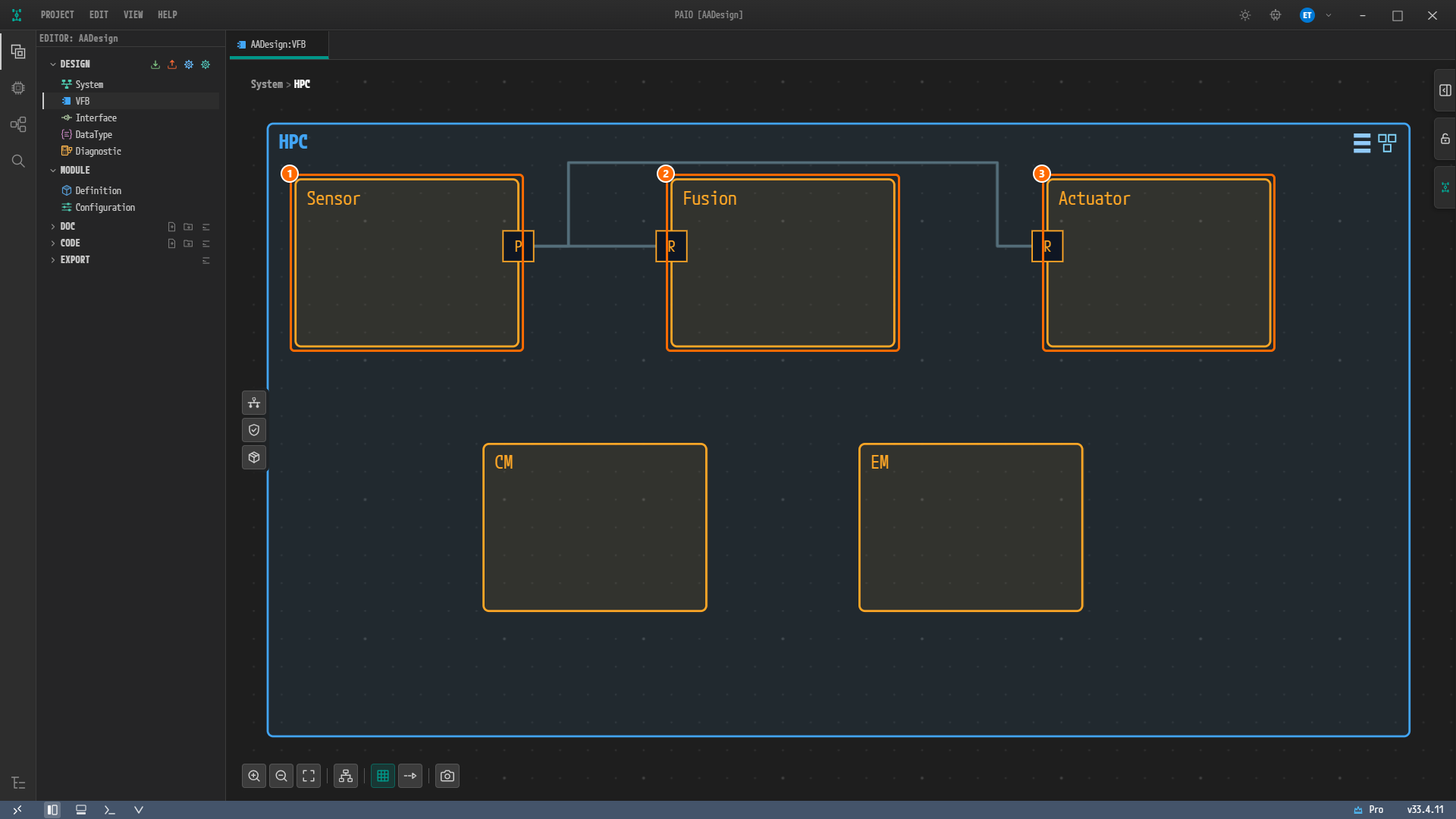
Figure 10-1. The VFB editor inside the composition
HPC. ① The nodeSensorto double-click first, ② the nodeFusion, ③ the nodeActuator. Only these three have ports, and connectors run from thePofSensorto the twoRports.CMandEMare not opened in this chapter. The node arrangement may differ from the figure depending on the result of Auto Layout in chapter 8; it has no effect on the design values. -
Double-click the node
Sensor. The dialog AA Internal Behavior [Sensor] opens. The canvas on the left shows the body ofSensorand thePportSensoron its edge; there is no mapping box yet. The panel on the right has the PROPERTIES tab open and shows NAMESensor, AS PROTOTYPESensor, DESCRIPTION-and the PORTS rowPSensorSensor.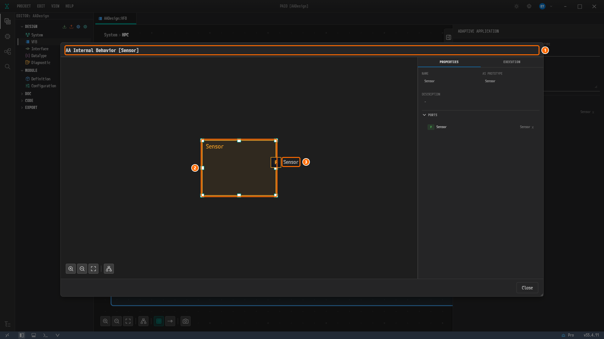
Figure 10-2. The dialog just after opening. ① The title AA Internal Behavior [Sensor], ② the body of
Sensoron the canvas, ③ the labelSensorof thePport on the right edge. There is no box inside the body yet.
Creating the Mapping Box from the Add Instance Menu
-
Right-click an empty spot of the
Sensorbody on the canvas. The menu shows two items, Add Port and Add Instance. -
Hover over Add Instance. The submenu lists eleven functional clusters in this order: ara::com, ara::log, ara::sm, ara::phm, ara::nm, ara::tsync, ara::crypto, ara::idsm, ara::diag, ara::per, ara::rds.
-
Hover over ara::com. Its submenu has a single item, Service Instance.
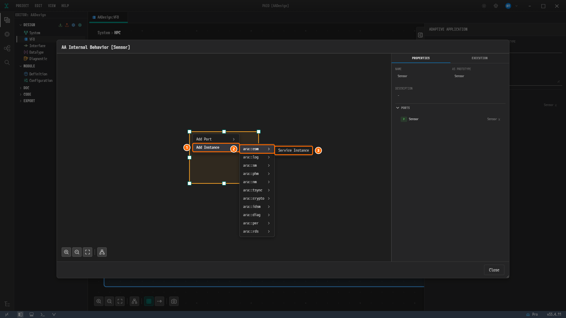
Figure 10-3. All three menu levels on one screen. ① Add Instance, ② the cluster ara::com, ③ Service Instance. Under Add Instance there are eleven clusters from ara::com to ara::rds.
-
Click Service Instance. A mapping box
Sensor/AA/appears inside the body and is selected, and the title gains a modified marker,● AA Internal Behavior [Sensor]. The panel on the right changes to SERVICE INSTANCE MAPPING. It has four fields — INSTANCE SPECIFIERSensor/AA/(read-only), PROCESSSensor(read-only), PORT (empty) and SERVICE INSTANCE (empty) — and the hintSelect a port and service instance to view detailsbelow them. PORT and SERVICE INSTANCE are required: while they are empty, their labels and underlines are red, with the messagesPort is requiredandService Instance is requiredbelow them.
Note. The other clusters under Add Instance create the mapping boxes of their own functional clusters. This tutorial uses ara::com only. The menu always lists all eleven clusters, whatever the machine holds.
Note. The INSTANCE SPECIFIER is
<Executable name>/<ROOT SWC PROTOTYPE>/<port>. In chapter 9 you left the NAME of the EXECUTABLE asSensorand the ROOT SWC PROTOTYPE at its defaultAA, so it starts withSensor/AA/, and the last segment is filled in once you pick the port. PROCESS is filled automatically withSensorbecause there is only one process from chapter 9, and it cannot be changed.
Picking the PORT
-
Click the PORT field. The dropdown lists the single port of this Adaptive Application,
Sensor.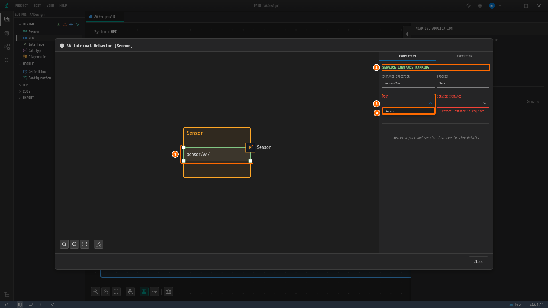
Figure 10-4. Right after creating the mapping box. ① The mapping box
Sensor/AA/inside the body, ② the panel title SERVICE INSTANCE MAPPING, ③ the PORT field, ④ the dropdown itemSensor. INSTANCE SPECIFIER isSensor/AA/, PROCESS isSensor, and SERVICE INSTANCE is empty. The labels of PORT and SERVICE INSTANCE are red, and the messageService Instance is requiredshows to the right of the open list. -
Click
Sensor. The mapping box changes toSensor/AA/Sensor, INSTANCE SPECIFIER changes toSensor/AA/Sensor, and a dashed arrow runs from the box to thePport. PORT is no longer red; SERVICE INSTANCE stays red withService Instance is requireduntil you pick an instance.
Caution. Pick PORT first and SERVICE INSTANCE second. The SERVICE INSTANCE dropdown offers only the instances that match the direction and the interface of the chosen port: providers only on a
Pport, consumers only on anRport, and only instances of the same service as the port's interfaceSensor.
Picking the SERVICE INSTANCE
-
Click the SERVICE INSTANCE field. The dropdown lists a single item,
Provider_Sensor (SOME/IP)— the port is aPport, so only providers pass the filter.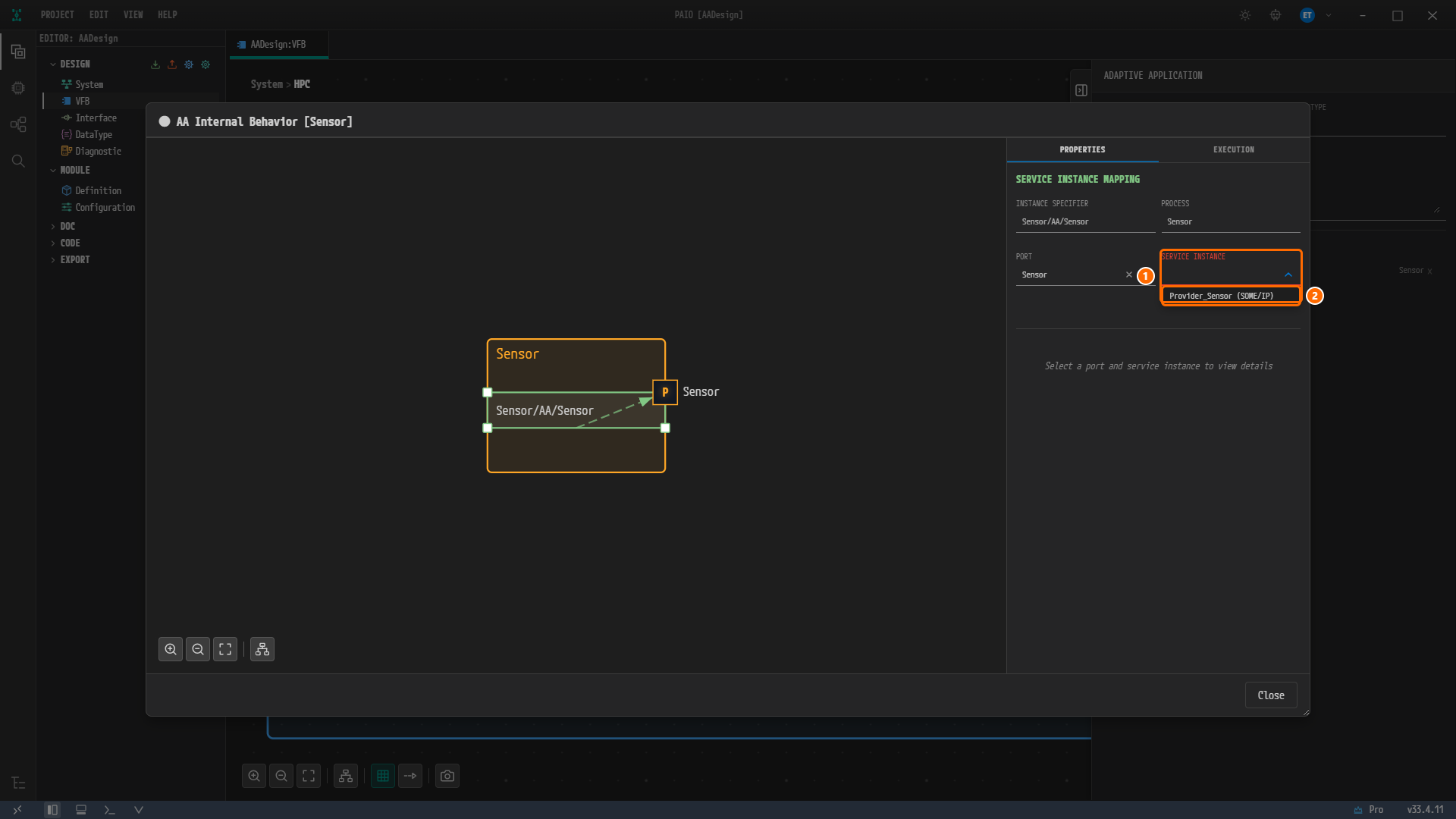
Figure 10-5. The screen after picking the port. ① The SERVICE INSTANCE field, ② the dropdown item
Provider_Sensor (SOME/IP). The box on the canvas readsSensor/AA/Sensorand a dashed arrow runs to thePport. The SERVICE INSTANCE label is still red; the open list covers its message. -
Click
Provider_Sensor (SOME/IP). Below the fields the read-back block REFERENCED INSTANCE appears with a SOME/IP badge and four lines:SERVICE ID = 0x000B,VERSION = 1.0,INSTANCE ID = 0x0001,ENDPOINT = 127.0.0.1:20003. Under it are the table EVENTS (columns EVENT, EVENT ID, EVENTGROUP ID, TRANSPORT; rowSensorData0x00010x0001UDP) and the table METHODS (columns METHOD, METHOD ID, TRANSPORT; rowCalculation0x0001UDP). This is a provider, so there is no CLIENT ID field.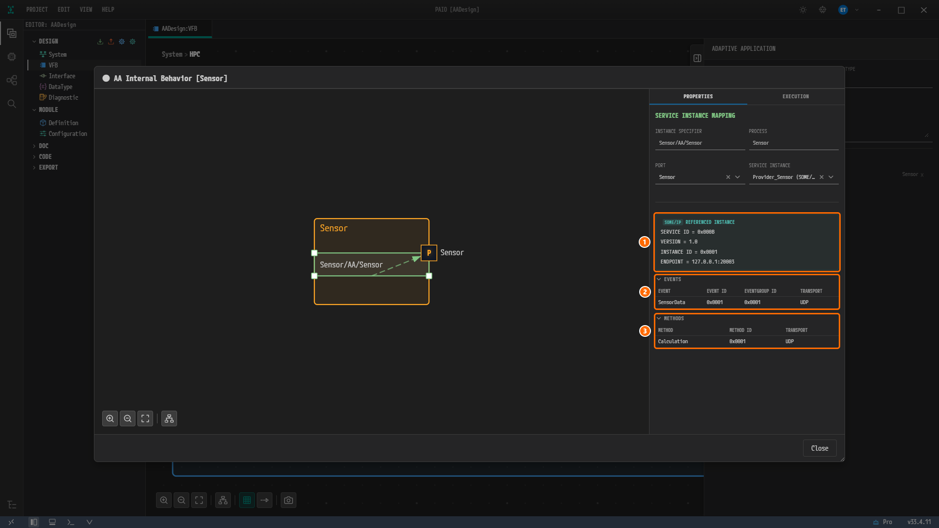
Figure 10-6. The panel after picking the instance. ① The read-back block REFERENCED INSTANCE (
SERVICE ID = 0x000B,VERSION = 1.0,INSTANCE ID = 0x0001,ENDPOINT = 127.0.0.1:20003), ② the table EVENTS, ③ the table METHODS. The SERVICE INSTANCE field is truncated toProvider_Sensor (SOME/…by its width, but its value isProvider_Sensor (SOME/IP). The title still reads● AA Internal Behavior [Sensor].
Note. The read-back block is entirely read-only.
0x000Bis the Service ID11set in chapter 6,0x0001is the Instance ID1ofProvider_Sensorfrom chapter 6,127.0.0.1is the unicast address ofeth0from chapter 3, and20003is the UDP port bound in chapter 7. You cannot change the values here; to change them, go back to the editors of chapters 6 and 7.
Saving and Closing
- Press
Ctrl+Sinside the dialog. The●disappears from the title, which becomesAA Internal Behavior [Sensor]. The mapping box and the panel values stay visible as they are. - Click Close. Since you saved, the dialog closes without asking.
Note. Until you press
Ctrl+S, the edit exists only in the dialog: the tabAADesign:VFBshows no modified marker●, and the V icon in the footer gets no badge for the empty PORT and SERVICE INSTANCE.Ctrl+Sinside the dialog writesservice-instance-mappingsintoSensor.swc.io.modeland saves theAADesign:VFBtab along with it. After closing, the tab carries no modified marker●.
Mapping the Port of Fusion to Fusion_Sensor
Fusion is a consumer. The procedure is the same as for Sensor with one addition, entering the CLIENT ID.
-
Double-click the node
Fusion. AA Internal Behavior [Fusion] opens, and the canvas shows the body ofFusionwith theRportSensoron its edge. The PORTS row readsRSensorSensor. -
Right-click the body and click Add Instance › ara::com › Service Instance. The box
Fusion/AA/appears and PROCESS isFusion. As forSensor, the empty PORT and SERVICE INSTANCE are red. -
Click the PORT field and pick
Sensor. The box becomesFusion/AA/Sensor. -
Click the SERVICE INSTANCE field. The dropdown lists two items,
Actuator_Sensor (SOME/IP)andFusion_Sensor (SOME/IP)— the port is anRport, so only the two consumers pass the filter. ClickFusion_Sensor (SOME/IP). -
Check the read-back block:
SERVICE ID = 0x000B,VERSION = 1.0,INSTANCE ID = 0xFFFF,ENDPOINT = 127.0.0.1:20002. The EVENTS and METHODS tables are the same as forSensor. Between the METHODS header and its table there is a CLIENT ID field with a DEC / HEX toggle to the right of its label; the default is HEX and the field is empty. -
Type
2into the CLIENT ID field and pressTab. The field shows0x2.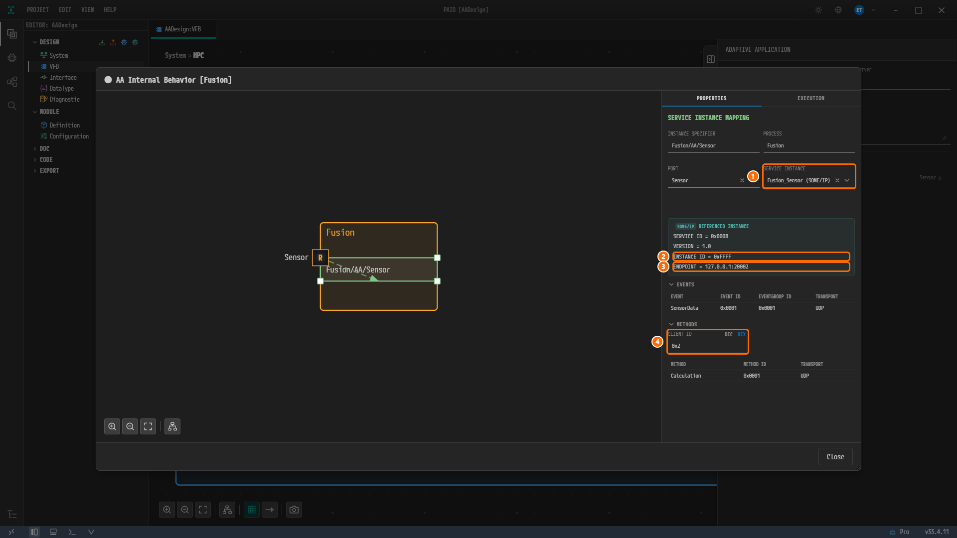
Figure 10-7. The
Fusiondialog after entering the CLIENT ID. ① The SERVICE INSTANCE fieldFusion_Sensor (SOME/IP), ② the read-back lineINSTANCE ID = 0xFFFF, ③ the read-back lineENDPOINT = 127.0.0.1:20002, ④ the CLIENT ID field (0x2, with HEX active on the DEC / HEX toggle). The boxFusion/AA/Sensoron the canvas is joined to theRport on the left edge by a dashed line, and its left end touches the port icon. The title reads● AA Internal Behavior [Fusion]. -
Press
Ctrl+S, then click Close.
Note. You can type the CLIENT ID without the
0xprefix. HEX is the default, so typing2shows0x2and the file stores2. The reference values1and2are the same in decimal and hexadecimal, so there is no need to switch the toggle. The consumers'INSTANCE ID = 0xFFFFcomes from leaving the Required Instance ID atANYin chapter 6; the model value is65535.
Mapping the Port of Actuator to Actuator_Sensor
Map Actuator the same way. Double-click the node, right-click the body and click Add Instance › ara::com › Service Instance, pick and enter the values from the table, then finish with Ctrl+S and Close.
| Node | PORT | SERVICE INSTANCE | CLIENT ID | Read-back INSTANCE ID / ENDPOINT |
|---|---|---|---|---|
Actuator | Sensor | Actuator_Sensor (SOME/IP) | 1 → 0x1 | 0xFFFF / 127.0.0.1:20001 |
The SERVICE INSTANCE dropdown shows the same two items as for Fusion, Actuator_Sensor (SOME/IP) and Fusion_Sensor (SOME/IP). Here you pick Actuator_Sensor (SOME/IP).
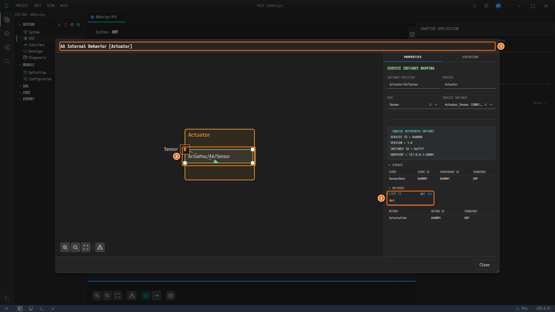
Figure 10-8. The Actuator dialog after saving with Ctrl+S. ① The title AA Internal Behavior [Actuator] (no modified marker), ② the mapping box Actuator/AA/Sensor, ③ the CLIENT ID field 0x1. The SERVICE INSTANCE field is truncated to Actuator_Sensor (SOME/…, and the read-back block reads INSTANCE ID = 0xFFFF, ENDPOINT = 127.0.0.1:20001. The box and the panel values stay visible after saving.
Caution. The dropdown items are the same on
FusionandActuator. Confirm from the ENDPOINT of the read-back block that you pickedFusion_Sensor (SOME/IP)onFusionandActuator_Sensor (SOME/IP)onActuator:Fusionmust read127.0.0.1:20002andActuatormust read127.0.0.1:20001.
Once all three dialogs are closed, the HPC canvas looks unchanged. Mapping boxes are visible only inside the dialog.
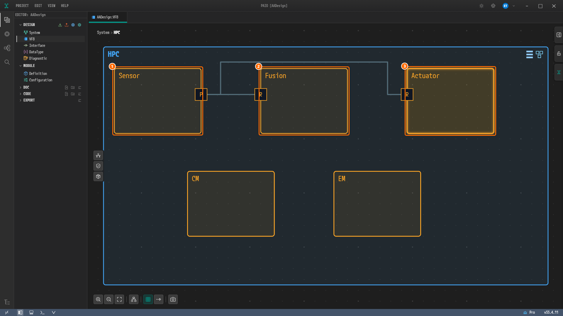
Figure 10-9. The HPC canvas after the mapping. ① Sensor, ② Fusion, ③ Actuator. Actuator, the last one opened, is still selected and highlighted, and the tab AADesign:VFB carries no modified marker ●.
Each of the three files gains one service-instance-mappings entry. The entry of Sensor.swc.io.model is:
"service-instance-mappings": [
  {
    "name": "Sensor_AA_Sensor",
    "port-ref": "Sensor",
    "service-instance-ref": "Provider_Sensor",
    "instance-type": "someip",
    "process-ref": "Sensor",
    "position": { "x": 0, "y": 48 },
    "size": { "width": 160, "height": 32 }
  }
]
In Fusion.swc.io.model the name is Fusion_AA_Sensor, the service-instance-ref is Fusion_Sensor, the process-ref is Fusion, and there is an additional client-id 2. In Actuator.swc.io.model they are Actuator_AA_Sensor, Actuator_Sensor and Actuator with client-id 1. The entry of the provider Sensor has no client-id key at all. The product builds name as <Executable>_<ROOT SWC PROTOTYPE>_<port>, and position and size are the coordinates of the box. CM.swc.io.model, EM.swc.io.model, SERVICE.io.model and IVC.io.model are unchanged. VFB.io.model is written again when you save a dialog, but only the modified time stamp in its metadata changes.
Viewing the Validation Result
-
Look at the V icon in the footer at the bottom of the window, the fifth icon from the left. It carries no badge.
-
Look at the VALIDATION panel. If it is closed, click the V icon in the footer. The header carries no badge, and under the column headers ELEMENT TYPE, NAME, DESCRIPTION and CONSTR the body reads
No validation issues..
Figure 10-10. The VALIDATION panel after saving all three dialogs. The body reads
No validation issues..
Note. This chapter saves only after both PORT and SERVICE INSTANCE are picked. What validation reports when you save with one of them empty was not checked in this chapter.
Why Is It Designed This Way?
- Only the three with ports are mapped. The reference design has three
SERVICE-INSTANCE-TO-PORT-PROTOTYPE-MAPPINGelements, one under theManifestof each ofSensor,FusionandActuator.CMandEMhave neither ports nor mappings. - The CLIENT ID is absent on the provider and
2,1on the consumers. In the reference design theCLIENT-IDunderPARA-SOMEIP-CONFIGURATIONis empty forSensor,2forFusionand1forActuator. PAIO shows no CLIENT ID field on a provider mapping, so the export carries an emptyCLIENT-ID, and the values entered on the consumers are exported as they are. - The name is
<Executable>_<ROOT SWC PROTOTYPE>_<port>. The three reference namesSensor_AA_Sensor,Fusion_AA_SensorandActuator_AA_Sensorfollow this rule, and they are reproduced exactly because chapter 9 left the ROOT SWC PROTOTYPE at its defaultAA. In the reference design onlyCMandEMuseRootSwComponent; those two have no mappings, so this does not affect any mapping name. - The exported
Sensor_AA_Sensorblock differs from the reference design in one line only. That line is theCONTEXT-ROOT-SW-COMPONENT-PROTOTYPE-REFof thePORT-PROTOTYPE-IREF. The export has/Executable/Sensor/Sensor/AA, which points at the root prototypeAAof the ExecutableSensor, while the reference design has/Executable/Sensor/AA, one level short, which names no element. The details are in ARXML Export. - The read-back block only shows the results of chapters 6 and 7.
SERVICE ID,INSTANCE IDandENDPOINTare not entered in this dialog. The mapping decides only which port uses which instance.
Checklist
- Double-clicking
Sensor,FusionandActuatorshows one mapping box inside each body —Sensor/AA/Sensor,Fusion/AA/Sensor,Actuator/AA/Sensor— with a dashed arrow between the box and the port. - Clicking the box shows the panel SERVICE INSTANCE MAPPING with PORT
Sensorand SERVICE INSTANCEProvider_Sensor (SOME/IP),Fusion_Sensor (SOME/IP)andActuator_Sensor (SOME/IP)respectively. - The read-back ENDPOINT is
127.0.0.1:20003forSensor,127.0.0.1:20002forFusionand127.0.0.1:20001forActuator, and the INSTANCE ID is0x0001forSensorand0xFFFFfor the other two. - The CLIENT ID of
Fusionis0x2, that ofActuatoris0x1, andSensorhas no CLIENT ID field. - Neither the dialog title nor the tab
AADesign:VFBcarries a modified marker●. -
CMandEMwere not opened and their files are unchanged. - The VALIDATION panel shows
No validation issues.and the header carries no badge.
Next Step
In Logging and DLT you enter the Application ID and the DLT contexts in the LOG CONFIG of the five processes.