Binding Service Instances to the Connector
What You Will Do
In this chapter you bind the three service instances created in SOME/IP Deployment and Service Instances to the Ethernet connector eth0 created in Topology — Ethernet Connector and Endpoints.
In the System editor you select the connector eth0, press the + button in the SERVICE INSTANCES section of the ETHERNET CONNECTOR panel, and open the modal Select Service Instance. You check all three instances and Bind them, pick the UDP PORT of each instance card from the UDP endpoints created in chapter 3, and save.
When you finish this chapter, the connector eth0 in design/IVC.io.model holds three bindings — Provider_Sensor on UDP 20003, Actuator_Sensor on UDP 20001 and Fusion_Sensor on UDP 20002. In ARXML Export these bindings become the three SOMEIP-SERVICE-INSTANCE-TO-MACHINE-MAPPING elements of the reference design.
Before You Begin
- Start from the state at the end of SOME/IP Deployment and Service Instances. The
design/folder containsIVC.io.model(connectoreth0with the UDP endpoints20001,20002and20003) andSERVICE.io.model(providerProvider_Sensor, consumersActuator_SensorandFusion_Sensor). No service instance is bound to the connectoreth0yet. - The VALIDATION panel shows
No validation issues.. Right after Bind it shows one error for each binding that has no UDP port yet; each port you pick removes one, so the chapter ends withNo validation issues.again. - You may close the
AADesign:Interfacetab left open in chapter 6. This chapter starts by opening System from DESIGN in the EDITOR view.
Nothing is typed on the keyboard in this chapter. The instances to bind and their ports are all picked from lists by clicking.
| Instance | Role | UDP PORT to pick | TCP PORT |
|---|---|---|---|
Provider_Sensor | Provider (badge P) | 20003 | leave empty |
Actuator_Sensor | Consumer (badge C) | 20001 | leave empty |
Fusion_Sensor | Consumer (badge C) | 20002 | leave empty |
Opening the SERVICE INSTANCES of the Connector eth0
Opening the System Editor and Selecting the Connector
-
In the EDITOR view on the left, click System under DESIGN. The tab
AADesign:Systemopens, and the canvas shows what you built in chapter 3: the HPC nodeEcu [HPC], the green square inside it (the controller), the square on the border of the node (the connectoreth0) and, joined to it by a blue line, the small blue square with the nameEthernetClusterunder it (the cluster). -
Click the connector
eth0on the node border. The ETHERNET CONNECTOR panel opens on the right and shows NAMEeth0, CONTROLLEREcu_EthernetControllerand CONNECTED CHANNELEthernetCluster / PhysicalChannel. Below are the sections NETWORK ENDPOINT, APPLICATION ENDPOINTS, SERVICE INSTANCES, SOCKET CONNECTIONS, PARTIAL NETWORK, TX PDUS and RX PDUS. -
Click the NETWORK ENDPOINT header to collapse it. APPLICATION ENDPOINTS is already collapsed; if it is expanded, collapse it the same way. This is optional and only tidies the screen.
-
Click the SERVICE INSTANCES header to expand it. The body shows
No service instances defined, and at the right end of the header is the + button (tooltipAdd Service Instance).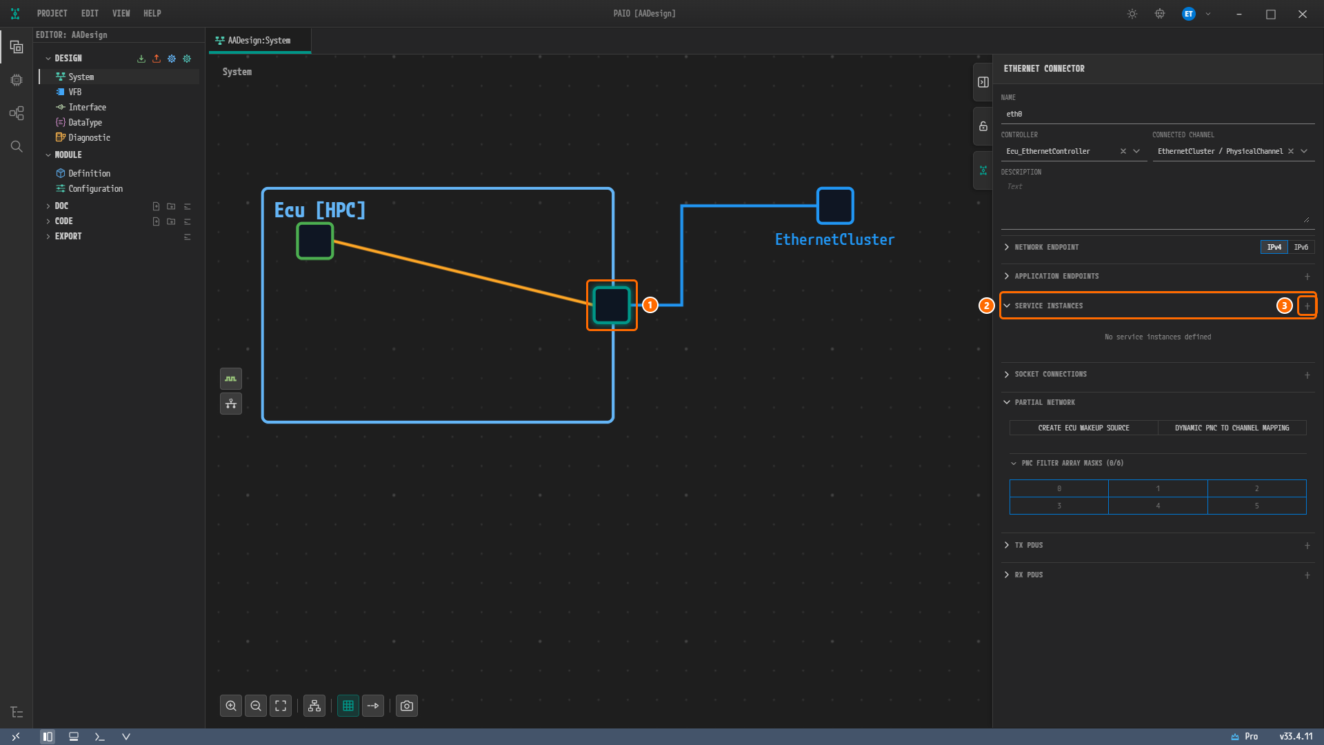
Figure 7-1. The System editor with the connector
eth0selected. ① The connectoreth0on the border of the nodeEcu [HPC](selected), ② the expanded SERVICE INSTANCES header, ③ the + button at the right of the header (tooltipAdd Service Instance). The body showsNo service instances defined.
Binding the Three Service Instances
Picking the Instances in the Modal
-
Click the + button in the SERVICE INSTANCES header. The modal Select Service Instance opens. The first column holds each row's checkbox and has no header; the other column headers are PROTOCOL, ROLE, INSTANCE, SERVICE, SERVICE ID and INSTANCE ID, and there are three rows.
SOME/IPPROVIDERProvider_SensorSensor111SOME/IPCONSUMERActuator_SensorSensor11ANYSOME/IPCONSUMERFusion_SensorSensor11ANY
-
Check the checkboxes of all three rows. Clicking anywhere in a row also toggles its checkbox.
-
Click the Bind button at the bottom right of the modal. Do not press Cancel on its left.
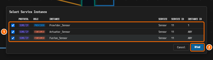
Figure 7-2. The modal Select Service Instance. ① The three rows, all checked —
Provider_Sensor(PROVIDER, INSTANCE ID1),Actuator_SensorandFusion_Sensor(CONSUMER, INSTANCE IDANY), ② the Bind button to click. The SERVICE column shows the deployment nameSensorand the SERVICE ID column shows11.
The modal lists the instances of design/SERVICE.io.model with the provider first and the consumers after it. The consumers' INSTANCE ID ANY is the REQUIRED INSTANCE ID ANY (model value 65535) you left unchanged in chapter 6. When you Bind all three rows at once, the cards are created in this same order.
Checking the Binding Result
-
The modal closes and three cards appear in the SERVICE INSTANCES section. Each summary line shows the badge
SOME/IP, the role badge P (provider) or C (consumer), the instance name and the delete ×; the port slot at the right of the summary line is still empty. -
The tab
AADesign:Systemgets the modified mark ●, and the V icon in the footer gets a red badge3.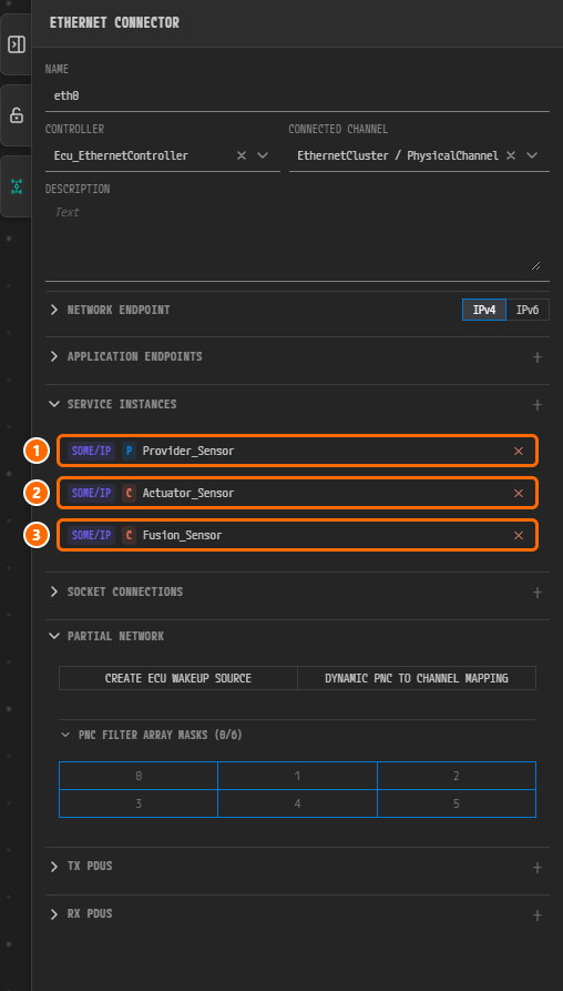
Figure 7-3. The SERVICE INSTANCES section right after binding. ① The card
SOME/IPPProvider_Sensor, ② the cardSOME/IPCActuator_Sensor, ③ the cardSOME/IPCFusion_Sensor. None of the three cards has a port at the right of its summary line.
The badge 3 counts three validation errors, one for each binding that has no UDP port yet. The VALIDATION panel (click the V icon if it is closed) shows the badge 3 next to its title and three rows, one per instance: ELEMENT TYPE SomeipServiceInstanceToMachineMapping, NAME the instance name, an empty CONSTR, and a DESCRIPTION such as Service "Sensor" uses UDP, but the mapping of "Provider_Sensor" on "Ecu/eth0" defines no UDP port.. At the default column widths ELEMENT TYPE and DESCRIPTION are cut off with …. Each port you pick in the next sections removes one of these errors.
Note. Bind binds the checked rows in a single edit. A provider instance can be bound to only one Ethernet connector in the project, while a consumer instance can be bound to each connector. An instance already bound to this connector is not listed in the modal again.
Assigning the UDP Port of the Provider Provider_Sensor
Of the three instances, the provider is shown as a procedure. The port is picked in the UDP PORT field of the card, from the list of endpoints created in chapter 3.
Expanding the Card and Opening the Port List
-
Click the summary line of the card
SOME/IPPProvider_Sensorto expand it. Three fields appear: IP ADDRESS127.0.0.1(read-only), TCP PORT (empty, hintUnsigned Integer (0..65535)) and UDP PORT (empty, same hint). Below them are the rows TLS (TCP) and TLS (UDP), each with a + button (tooltipAdd TLS). -
Click the ▾ button to the right of the UDP PORT field (tooltip
Select from Application Endpoints). A list20001,20002,20003opens below the field.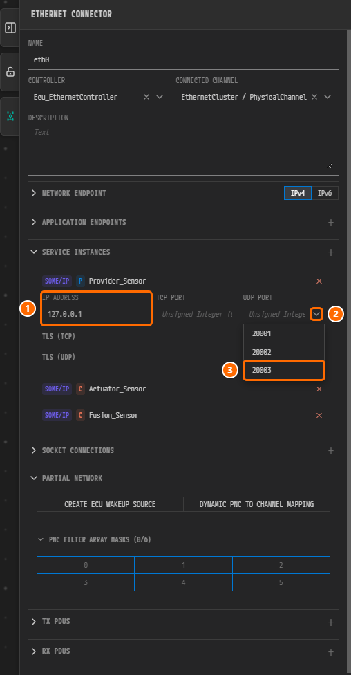
Figure 7-4. The expanded
Provider_Sensorcard with the UDP PORT list open. ① IP ADDRESS =127.0.0.1(read-only), ② the ▾ button to the right of the UDP PORT field, ③ the item20003to click in the list. The TCP PORT field has no ▾ button, and the open list covers the + buttons of the rows TLS (TCP) and TLS (UDP).
IP ADDRESS is filled with the unicast address of the connector eth0 and cannot be changed. The three items in the list are the ports of the UDP endpoints in the APPLICATION ENDPOINTS of this connector. Since no TCP endpoint was created, the TCP PORT field gets no ▾ button. The rows TLS (TCP) and TLS (UDP) hold this binding's TLS settings for TCP and for UDP; the reference design has none, so this chapter leaves them empty.
Picking the Port 20003
-
Click
20003in the list. The UDP PORT field now holds20003, and the card stays expanded. The badge on the V icon in the footer changes to2. -
Click the connector
eth0on the canvas again to redraw the panel, then click the summary line of the cardProvider_Sensorto expand it again. The right of the summary line showsUDP:20003, and the UDP PORT field is20003. -
Leave TCP PORT and the rows TLS (TCP) and TLS (UDP) empty.
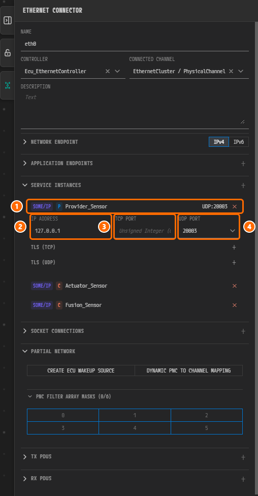
Figure 7-5. The
Provider_Sensorcard after picking the port. ①UDP:20003at the right of the summary line, ② IP ADDRESS =127.0.0.1, ③ the TCP PORT left empty, ④ UDP PORT =20003. Below them the rows TLS (TCP) and TLS (UDP) stay empty, each showing only its + button. The two cards below,Actuator_SensorandFusion_Sensor, are collapsed and have no port yet.
Note. Right after you pick a port, the summary line does not change yet; only the UDP PORT field receives the value. Once you click the connector again and the panel is redrawn,
UDP:20003is appended to the summary line. Instead of picking from the list you may also type a number into the UDP PORT field, but this chapter only uses the list.
Assigning the Ports of the Consumers Actuator_Sensor and Fusion_Sensor
Pick the ports of the two consumers the same way. Only the item to pick differs.
| Card | Item to click in the UDP PORT list | Summary line |
|---|---|---|
SOME/IP C Actuator_Sensor | 20001 | UDP:20001 |
SOME/IP C Fusion_Sensor | 20002 | UDP:20002 |
-
Click the summary line of the card
Actuator_Sensorto expand it, click the ▾ button of the UDP PORT field, and click20001in the list. The badge on the V icon changes to1. -
Click the summary line of the card
Fusion_Sensorto expand it, click the ▾ button of the UDP PORT field, and click20002in the list. The badge on the V icon disappears. -
Click the connector
eth0again. The three cards are shown collapsed withProvider_SensorUDP:20003,Actuator_SensorUDP:20001andFusion_SensorUDP:20002in their summary lines. -
Click the APPLICATION ENDPOINTS header to expand it. The three cards from chapter 3,
UDPeth0, 127.0.0.1:20001,UDPeth0, 127.0.0.1:20002andUDPeth0, 127.0.0.1:20003, are still there and no new endpoint has appeared.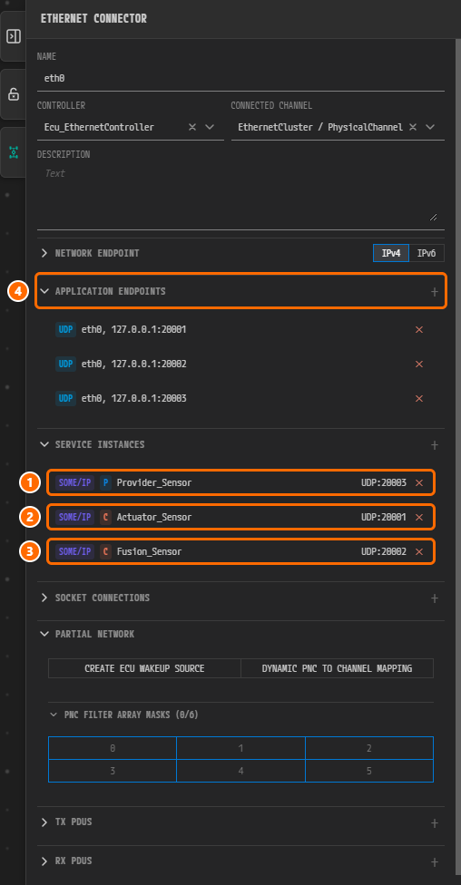
Figure 7-6. The panel after all ports are assigned. ①
Provider_SensorUDP:20003, ②Actuator_SensorUDP:20001, ③Fusion_SensorUDP:20002, ④ the expanded APPLICATION ENDPOINTS — the three cardsUDPeth0, 127.0.0.1:20001/:20002/:20003are unchanged from chapter 3.
A port picked from the list references the UDP endpoint with the same number as it is. That is why the number of cards in APPLICATION ENDPOINTS stays at three.
Saving
-
Click an empty spot on the canvas to deselect the connector.
-
Press
Ctrl+S. The modified mark ● on the tabAADesign:Systemdisappears anddesign/IVC.io.modelis saved. -
Click the connector
eth0again. SERVICE INSTANCES shows the cardsProvider_SensorUDP:20003,Actuator_SensorUDP:20001andFusion_SensorUDP:20002. If you expand the TX PDUS and RX PDUS headers, both showNo PDUs referenced.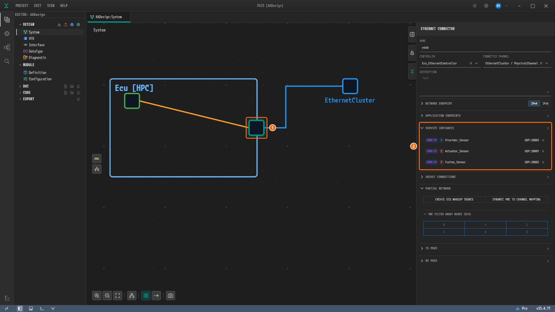
Figure 7-7. The System editor after saving. ① The connector
eth0selected again, ② the three cards in the SERVICE INSTANCES section —Provider_SensorUDP:20003,Actuator_SensorUDP:20001,Fusion_SensorUDP:20002. The tabAADesign:Systemhas no modified mark ●, and the V icon in the footer carries no badge.
The following entry is added to the connector eth0 in the saved design/IVC.io.model. Everything else (NETWORK ENDPOINT, APPLICATION ENDPOINTS and so on) stays as saved in chapter 3.
"service-instances": [
  { "instance-type": "someip", "instance-ref": "Provider_Sensor", "role": "provider", "udp-port": 20003 },
  { "instance-type": "someip", "instance-ref": "Actuator_Sensor", "role": "consumer", "udp-port": 20001 },
  { "instance-type": "someip", "instance-ref": "Fusion_Sensor",   "role": "consumer", "udp-port": 20002 }
]
For the TCP PORT left empty, no tcp-port key is written at all, and the empty rows TLS (TCP) and TLS (UDP) write nothing either. design/SERVICE.io.model does not change.
Viewing the Validation Result
-
Look at the V icon in the footer at the bottom of the window, the fifth icon from the left. It carries no badge, but its tooltip still reads
Validation: 1 error(s), 0 warning(s), 0 info(s), the last non-zero count; the VALIDATION panel shows the current result. -
Look at the VALIDATION panel. If it is closed, click the V icon in the footer.

Figure 7-8. The VALIDATION panel after saving. The header carries no badge, and under the column headers ELEMENT TYPE, NAME, DESCRIPTION and CONSTR there is the single line
No validation issues..
Note. The three errors that appeared right after Bind are gone; each one left when its binding got its UDP port. There is no row for the three bindings created in this chapter, the connector
eth0, the endpointsEcu_eth0_UDP_20001,Ecu_eth0_UDP_20002andEcu_eth0_UDP_20003, or the PDUs of the automatically derived signals. Even if you skip chapter 6 and start from this chapter, the same automatic derivation runs the moment you press Bind, and it adds no finding either.
Why Is It Designed This Way?
- The three bindings are the three
SOMEIP-SERVICE-INSTANCE-TO-MACHINE-MAPPINGelements of the reference design. The reference design has the mappingsEcu_ProviderMapping_Provider_Sensor(SERVICE-INSTANCE-REFProvider_Sensor,UDP-PORT-REFEcu_eth0_UDP_20003),Ecu_ConsumerMapping_Actuator_Sensor(Actuator_Sensor,Ecu_eth0_UDP_20001) andEcu_ConsumerMapping_Fusion_Sensor(Fusion_Sensor,Ecu_eth0_UDP_20002), and all three point toEcu/eth0throughCOMMUNICATION-CONNECTOR-REF. The instance and port combinations of this chapter are those values. - The mapping names are not entered. The names
{HPC}_{Provider|Consumer}Mapping_{instance}are assigned by the exporter in ARXML Export. The screen shows only the instance name and the port. - The ports are picked from the endpoints of chapter 3. The reference design has only the three
AP-APPLICATION-ENDPOINTelementsEcu_eth0_UDP_20001,Ecu_eth0_UDP_20002andEcu_eth0_UDP_20003, and the mappings reference these three. Picking from the list references the endpoint with the same number as it is, so no endpoint is added. - TCP PORT is left empty. The reference design has no TCP endpoint and no
TCP-PORT-REFin the mappings. Leaving the field empty means notcp-portkey is written. - The provider gets
20003, the consumers20001and20002. That is how theUDP-PORT-REFof the reference design is set. Because the TRANSPORT of the eventSensorDataand the methodCalculationin the chapter 6 deployment is UDP, only UDP ports are needed.
Checklist
- The SERVICE INSTANCES of the connector
eth0has the three cardsSOME/IPPProvider_Sensor,SOME/IPCActuator_SensorandSOME/IPCFusion_Sensor, in this order. - The right of the summary lines shows
UDP:20003,UDP:20001andUDP:20002respectively. - When a card is expanded, IP ADDRESS is
127.0.0.1, TCP PORT is empty, UDP PORT is20003,20001and20002respectively, and the rows TLS (TCP) and TLS (UDP) are empty. - APPLICATION ENDPOINTS has only the three cards from chapter 3,
UDPeth0, 127.0.0.1:20001/:20002/:20003. - TX PDUS and RX PDUS show
No PDUs referenced. - The tab
AADesign:Systemhas no modified mark ●. - The VALIDATION panel shows
No validation issues.and the header carries no badge.
Next Step
In Adaptive Applications and Ports, you create the five Adaptive Applications Sensor, Fusion, Actuator, CM and EM and attach ports of the service interface Sensor to them.