Exporting the ARXML
What You Will Do
In this chapter you export the design that passed Validation to AUTOSAR ARXML files. When you click Export, the icon on the DESIGN header of the EDITOR view, five files appear in the project's export folder straight away, without being asked for a save location.
Next you use the XML editor to see what ARXML the values you entered on screen in the earlier chapters have become. You follow one representative application, Sensor: the PROCESS Sensor and its startup conditions created in Executables and Processes, the mapping Sensor_AA_Sensor created in Service Instance Mapping, and the DLT application SENS created in Logging and DLT. The first two are in AADesign_SWC.arxml, and the DLT application is in AADesign_COM.arxml.
Finally you read a table of where, and why, your export differs from the five files EM_Test_*.arxml of the reference design.
When you finish this chapter, the export folder holds the five files AADesign_COM.arxml, AADesign_DataType.arxml, AADesign_Interface.arxml, AADesign_SWC.arxml and AADesign_System.arxml, and the status bar of the XML editor shows ✓ No problems for both files you opened.
Before You Begin
- Start from the state at the end of Validation. The VALIDATION panel, which the V icon in the footer opens, shows
No validation issues.. If the panel is open, close it with the V icon. - The project's
exportfolder is empty. If the tabAADesign:VFBfrom Validation is still open, click its × to close it, so that no editor is open. - The only things you type on the keyboard in this chapter are three strings in the find widget and one
Enter. The first string matches two places in its file, and the other two match exactly one place each.
| What to find | File | Search string | Find widget | Line it jumps to |
|---|---|---|---|---|
PROCESS Sensor | AADesign_SWC.arxml | /Executable/Sensor/Sensor | 1 of 2, then 2 of 2 after Enter | line 562, then line 575 |
Mapping Sensor_AA_Sensor | AADesign_SWC.arxml | Sensor_AA_Sensor | 1 of 1 | line 553 |
DLT application SENS | AADesign_COM.arxml | <APPLICATION-ID>SENS | 1 of 1 | line 446 |
Exporting the Project
Clicking the Export Icon
-
In the EDITOR view, point the mouse at the second of the four icons on the right of the DESIGN header. The tooltip Export appears. The four icons carry no label other than their tooltips, which read, from the left, Import, Export, PRTE Code Generation and PARA Code Generation.
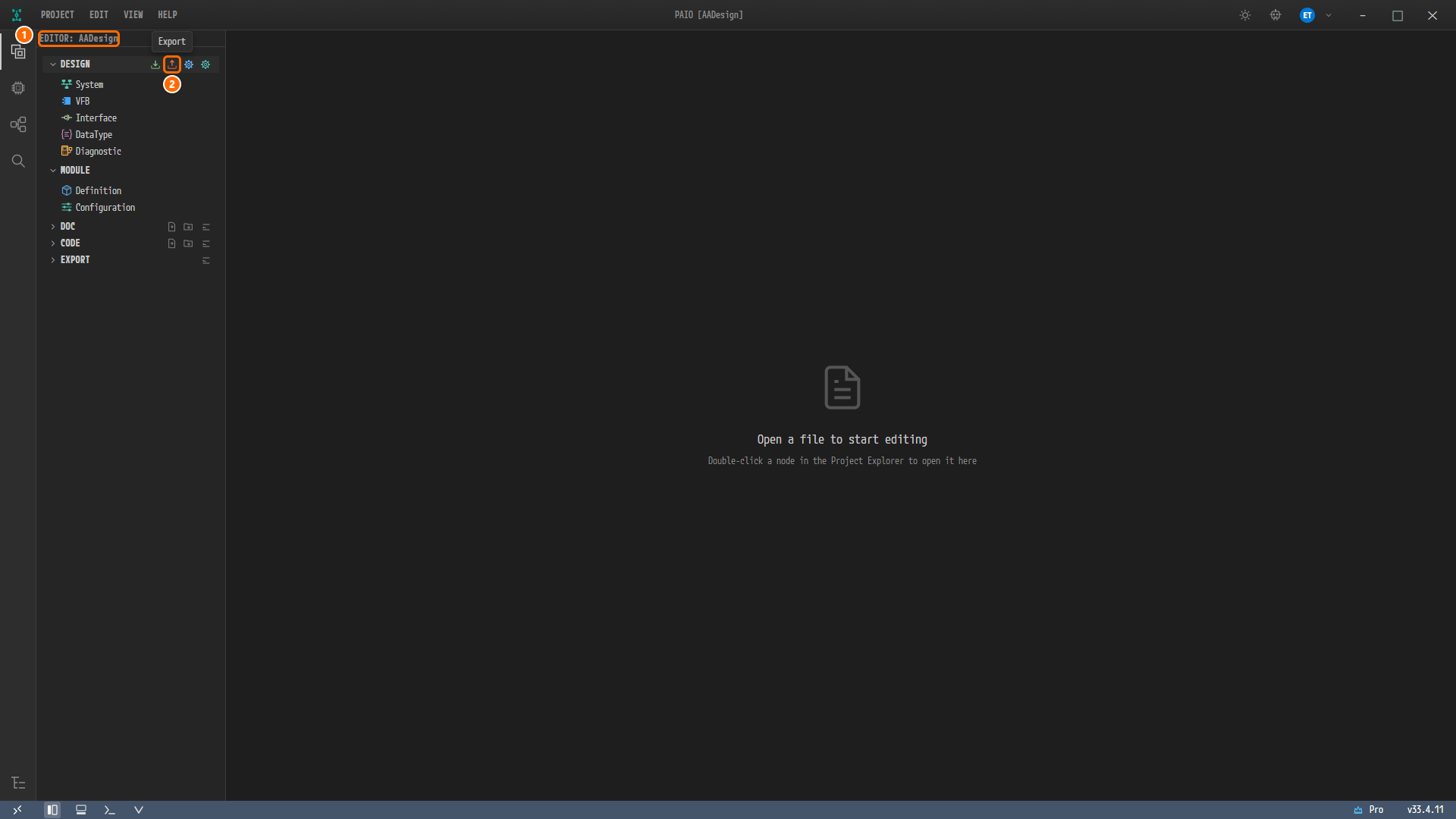
Figure 13-1. The Export icon of the DESIGN header. ① The view header
EDITOR: AADesign, ② the Export icon under the mouse, with its tooltip Export. DESIGN and MODULE are open, and DOC, CODE and EXPORT are closed. No tab is open, so the editor area showsOpen a file to start editing. -
Click Export.
Note. Export is also in the menu that opens when you right-click the
designfolder in the Explorer (the Explorer icon at the bottom of the icon bar on the far left). Both run the same export.
Checking the Progress Dialog
-
No file picker and no save-location dialog appears. The progress dialog Exporting to AUTOSAR opens immediately. A moment later the export finishes and the message changes to
Export complete: 30 elements exported to AADesign_*.arxml.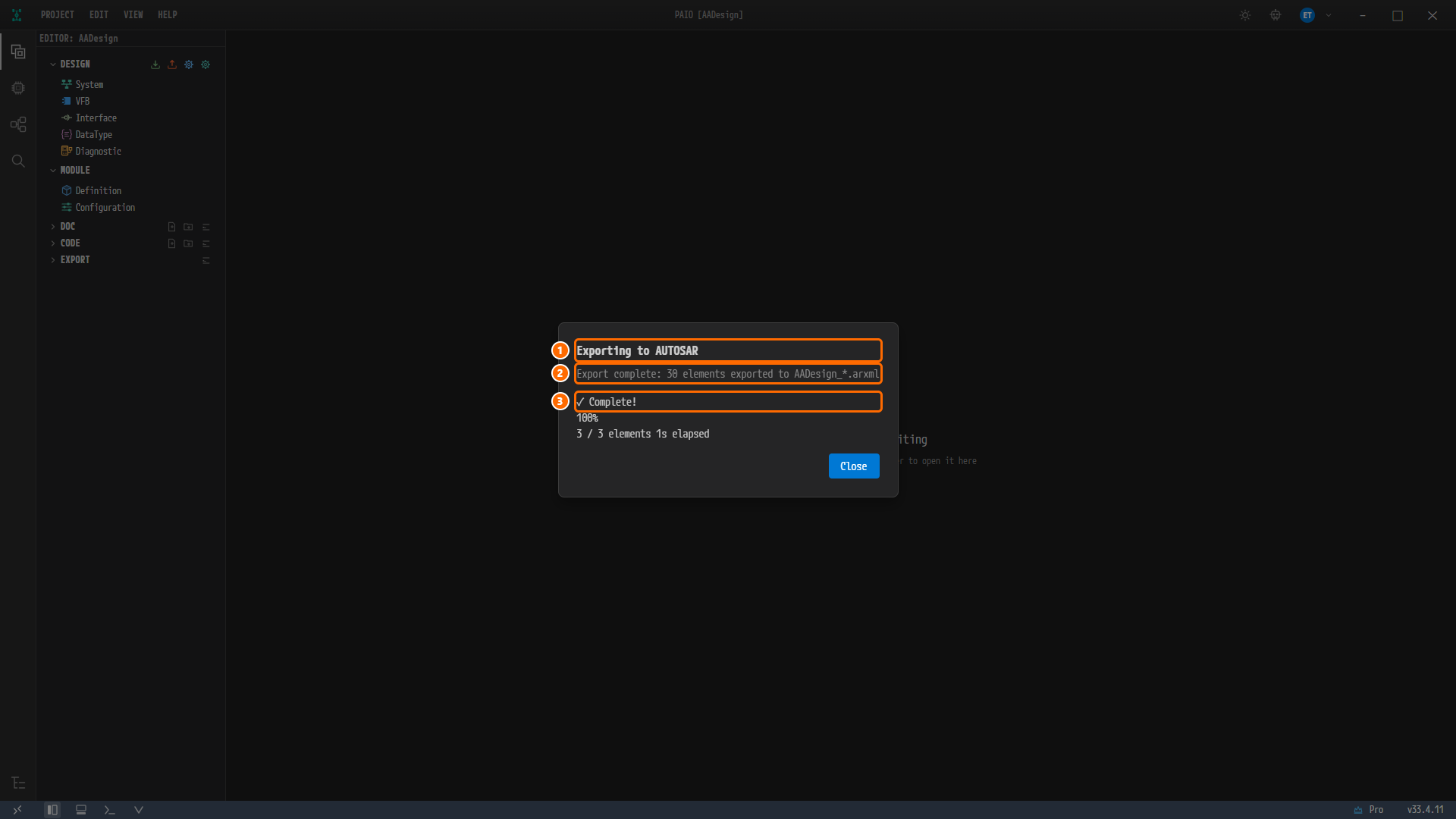
Figure 13-2. The progress dialog at the moment the export finishes. ① The dialog title Exporting to AUTOSAR, ② the message
Export complete: 30 elements exported to AADesign_*.arxml, ③ the phase indicator✓ Complete!. Below it are100%,3 / 3 elementswith the elapsed time, and the Close button. -
The progress dialog closes by itself 2 seconds after completion. You can wait, or click Close.
Note. The export always writes to the project's
exportfolder, with the names<project name>_*.arxml. The design files in thedesignfolder do not change. The elapsed time in the progress dialog varies between0sand1sfrom run to run.
Note. If you import the reference design into PAIO and export it again unchanged, the number in the message is larger than
30. The imported project contains additional derived elements that this tutorial does not create. The differences in file content are covered in the section "How Your Export Differs from the Reference Files" at the end of this chapter.
Viewing the Five Files in the export Folder
-
In the EDITOR view, click the EXPORT header to expand it. EXPORT lists the files of the project's
exportfolder: five files appear in name order, and no name is cut off.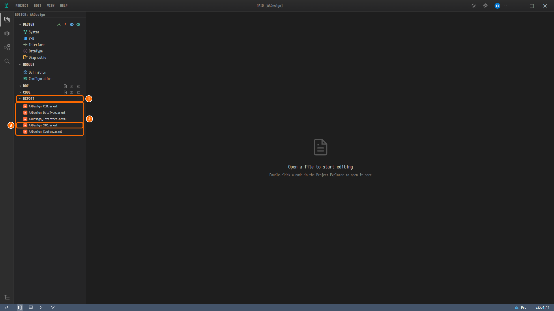
Figure 13-3. The expanded EXPORT section. ① The EXPORT header, ② the five files
AADesign_COM.arxml,AADesign_DataType.arxml,AADesign_Interface.arxml,AADesign_SWC.arxmlandAADesign_System.arxml, ③AADesign_SWC.arxml, which you open next.
The five files contain the following. All five files use the schema AUTOSAR_00054, and checking them against the schema bundled with PAIO gives 0 errors and 0 warnings. The sizes may differ slightly depending on the PAIO version.
| File | Contents | Size (bytes) |
|---|---|---|
AADesign_COM.arxml | The machine design Ecu, the Ethernet cluster and the connector eth0, the endpoints, the SOME/IP deployment and service instances, the mappings of instances to the machine, the DLT ECU and DLT applications, the DLT contexts, the event group subscription timing of the two consumers | 28 444 |
AADesign_DataType.arxml | The data types ByteArray and String, the primitive types and their CP-side mirrors, the pointer types VoidPtr and ConstVoidPtr | 39 671 |
AADesign_Interface.arxml | The service interface Sensor | 3 317 |
AADesign_SWC.arxml | The five Adaptive Applications and their ports, the compositions HPC and System, the Executables, the Processes, the startup configurations, the service instance mappings, the mappings of DLT applications to processes, the machine Ecu and its modules | 42 260 |
AADesign_System.arxml | The system System and the mapping SwMapping_HPC_to_Ecu that places the composition HPC on the machine design Ecu | 2 513 |
Opening AADesign_SWC.arxml in the XML Editor
-
In EXPORT, double-click
AADesign_SWC.arxml. The editor tabAADesign:AADesign_SWC.arxmlopens, showing the file from line 1. -
Look at the status bar below the editor. It shows
Ln 1, Col 1,UTF-8,Schema: R25-11and✓ No problems. When it opens a file, the XML editor automatically checks it against the AUTOSAR schema bundled with PAIO.✓ No problemsmeans there are no schema errors. The PROBLEMS header above it stays collapsed because there are no errors.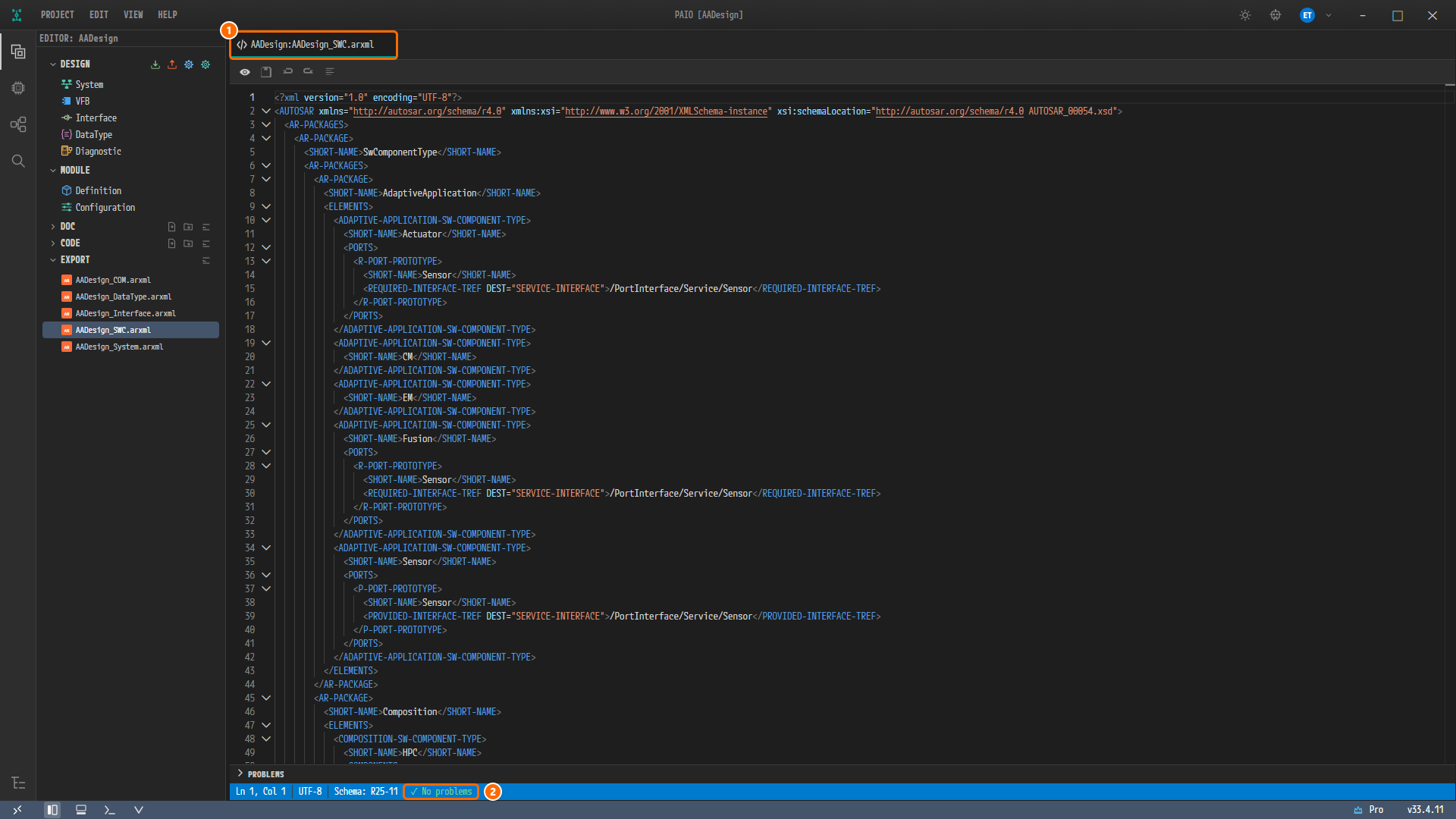
Figure 13-4. Right after opening
AADesign_SWC.arxml. ① The editor tabAADesign:AADesign_SWC.arxml, ②✓ No problemsin the status bar. The file is selected in EXPORT, and the start of the editor shows theADAPTIVE-APPLICATION-SW-COMPONENT-TYPEelementsActuator,CM,EM,FusionandSensorin turn.
Note. The file opens in view mode (read-only). The first toolbar button, with the tooltip Switch to Edit mode, switches to edit mode. The other buttons are Save (Ctrl+S), Undo (Ctrl+Z), Redo (Ctrl+Y) and Format XML (Shift+Alt+F). You do not change the file in this chapter, so do not switch to edit mode.
Viewing PROCESS Sensor and Its Startup Conditions
Jumping to PROCESS Sensor with Find
-
Click inside the editor and press
Ctrl+F. The find widget opens at the top right of the editor. -
Type
/Executable/Sensor/Sensor. The find widget shows1 of 2, and the editor jumps to line 562, inside the service instance mapping you view in the next section. PressEnteronce. The find widget shows2 of 2, and the editor jumps to line 575 and selects those characters. The status bar showsLn 575, Col 80and25 selected. -
Line 575 is in the lower part of the editor. To see the whole block, roll the mouse wheel down a few notches so that line 572
<PROCESS>, three lines above, comes to the top of the editor.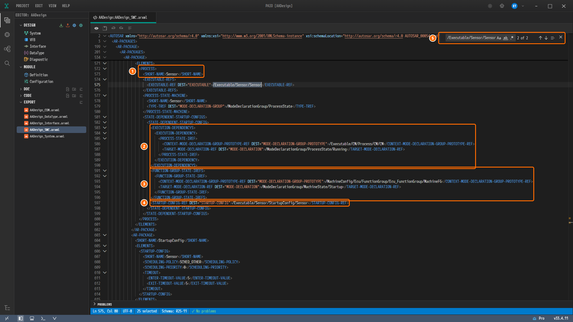
Figure 13-5.
PROCESS Sensorreached with find (lines 571-614). ① Lines 572-573,<PROCESS>andSHORT-NAMESensor, ② lines 583-590,EXECUTION-DEPENDENCY(RunningofCM), ③ lines 591-596,FUNCTION-GROUP-STATE-IREF(StartupofMachineFG), ④ line 597,STARTUP-CONFIG-REF, ⑤ the find widget (/Executable/Sensor/Sensor,2 of 2). The matched characters are selected on line 575, andSTARTUP-CONFIGSensorfollows from line 603.
Note. The top five lines of the editor (line numbers
2,3,199,201,534) are not the file content at that position. They are a header that pins the ancestor elements of the visible lines (AUTOSAR,AR-PACKAGES,AR-PACKAGE…) to the top of the editor.
Reading the Block
The lines of PROCESS Sensor, and where their values were entered, are as follows.
| Line | Content | Where it was entered on screen |
|---|---|---|
| 572-573 | <PROCESS>, <SHORT-NAME>Sensor</SHORT-NAME> | The Process name in Executables and Processes |
| 575 | EXECUTABLE-REF = /Executable/Sensor/Sensor | The Executable in the same chapter (already filled in) |
| 577-580 | PROCESS-STATE-MACHINE Sensor, TYPE-TREF = /ModeDeclarationGroup/ProcessState | Nothing entered. The exporter creates it |
| 583-590 | EXECUTION-DEPENDENCY › PROCESS-STATE-IREF: /Executable/CM/Process/CM/CM, /ModeDeclarationGroup/ProcessState/Running | The EXECUTION DEPENDENCY row CM : Running — start after the CM process has reached Running |
| 591-596 | FUNCTION-GROUP-STATE-IREF: /MachineConfig/Ecu/FunctionGroup/Ecu_FunctionGroup/MachineFG, /ModeDeclarationGroup/MachineState/Startup | The FUNCTION GROUP STATE row MachineFG : Startup |
| 597 | STARTUP-CONFIG-REF = /Executable/Sensor/StartupConfig/Sensor | Nothing entered. It points at the startup configuration below |
| 603-616 | STARTUP-CONFIG Sensor: SCHEDULING-POLICY SCHED_OTHER, SCHEDULING-PRIORITY 0, ENTER-TIMEOUT-VALUE 5, EXIT-TIMEOUT-VALUE 5 | ENTER TIMEOUT 5 and EXIT TIMEOUT 5 in STARTUP CONFIG |
The other processes have the same shape. Look at the following lines in the same file.
| Process | Where to look | Content |
|---|---|---|
Actuator | lines 251-258 | The same EXECUTION-DEPENDENCY as Sensor (/Executable/CM/Process/CM/CM, Running) |
Fusion | lines 488-495 | The same EXECUTION-DEPENDENCY |
EM | lines 394-414 | FUNCTION-GROUP-STATE-IREF (MachineFG, Startup). This is a deliberate departure from the reference design. See the "SWC File" table at the end of this chapter |
Viewing the Service Instance Mapping Sensor_AA_Sensor
Changing the Search String
-
Clear the input box of the find widget and type
Sensor_AA_Sensor. The find widget shows1 of 1, and the editor jumps to line 553. The status bar showsLn 553, Col 47and16 selected. -
As before, roll the mouse wheel down so that line 552 comes to the top of the editor.
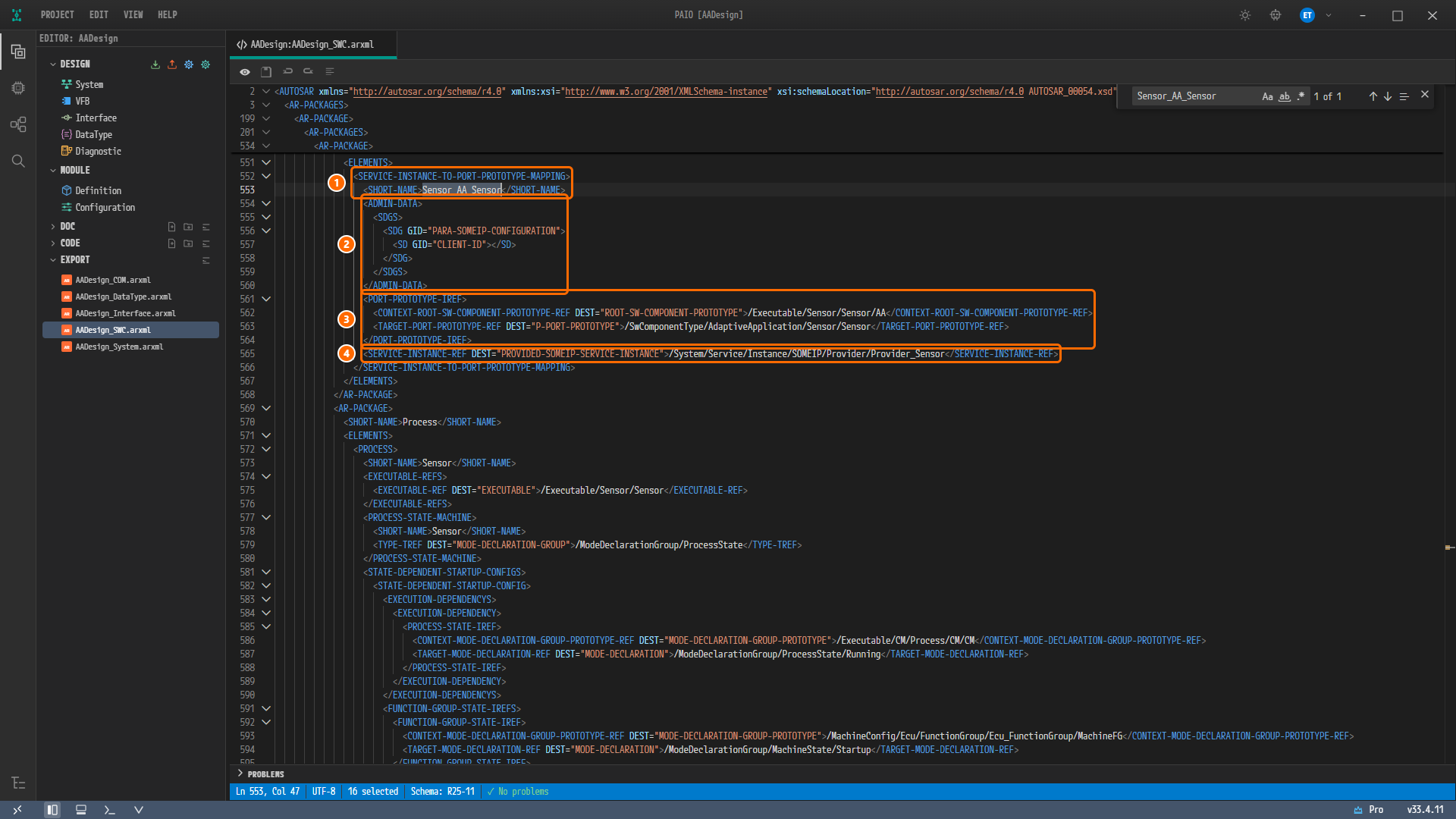
Figure 13-6. The mapping block reached with find (lines 551-594). ① Lines 552-553,
SERVICE-INSTANCE-TO-PORT-PROTOTYPE-MAPPINGandSHORT-NAMESensor_AA_Sensor, ② lines 554-560,ADMIN-DATA(CLIENT-IDempty), ③ lines 561-564,PORT-PROTOTYPE-IREF, ④ line 565,SERVICE-INSTANCE-REF(Provider_Sensor). From line 569 downward theProcesspackage and the beginning ofPROCESS Sensorare visible.
Reading the Block
| Line | Content | Meaning |
|---|---|---|
| 552-553 | SHORT-NAME Sensor_AA_Sensor | The naming rule <Executable>_<ROOT SWC PROTOTYPE>_<port> |
| 554-560 | SDG GID="PARA-SOMEIP-CONFIGURATION" › <SD GID="CLIENT-ID"></SD> | Empty because this is the provider mapping |
| 562 | CONTEXT-ROOT-SW-COMPONENT-PROTOTYPE-REF = /Executable/Sensor/Sensor/AA | The root prototype AA of the Executable Sensor |
| 563 | TARGET-PORT-PROTOTYPE-REF DEST="P-PORT-PROTOTYPE" = /SwComponentType/AdaptiveApplication/Sensor/Sensor | The P port Sensor of Sensor |
| 565 | SERVICE-INSTANCE-REF DEST="PROVIDED-SOMEIP-SERVICE-INSTANCE" = /System/Service/Instance/SOMEIP/Provider/Provider_Sensor | The provided instance Provider_Sensor from SOME/IP Deployment and Service Instances |
The two consumer-side mappings have the same shape; only their CLIENT-ID has a value.
| Mapping | CLIENT-ID | Line |
|---|---|---|
Sensor_AA_Sensor | empty | line 557 |
Actuator_AA_Sensor | 1 | line 225 |
Fusion_AA_Sensor | 2 | line 462 |
Note. In the file, the mappings come before the
PROCESSelements. That is whyPROCESS Sensorappears again at the bottom of Figure 13-6.
Note. Line 562 points at the root prototype
AAinside theEXECUTABLESensor, which sits in the package/Executable/Sensor. That is why the path namesSensortwice, and why the search string/Executable/Sensor/Sensoralso found this line. The same block in the reference design has/Executable/Sensor/AAthere, one level short, which names no element. This line is the only difference between the two blocks.
Viewing the DLT Application SENS
DLT-APPLICATION is in AADesign_COM.arxml, not in AADesign_SWC.arxml. AADesign_SWC.arxml contains only the DLT-APPLICATION-TO-PROCESS-MAPPING Mapping_SENS_TO_Sensor (lines 620-624), which ties that application to the process.
Opening AADesign_COM.arxml and Searching
-
In EXPORT, double-click
AADesign_COM.arxml. A second tab,AADesign:AADesign_COM.arxml, opens. The status bar shows✓ No problems. -
Click inside the editor, press
Ctrl+Fand type<APPLICATION-ID>SENS. The find widget shows1 of 1, and the editor jumps to line 446. The status bar showsLn 446, Col 39and20 selected. -
Roll the mouse wheel down so that line 435
<DLT-APPLICATION>, eleven lines above, comes to the top of the editor.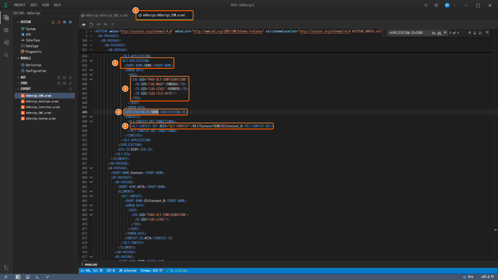
Figure 13-7.
DLT-APPLICATIONSENSinAADesign_COM.arxml(lines 434-477). ① The editor tabAADesign:AADesign_COM.arxml, ② lines 435-436,DLT-APPLICATIONandSHORT-NAMESENS, ③ lines 439-443,PARA-DLT-CONFIGURATION(CONSOLE,VERBOSE), ④ line 446,APPLICATION-IDSENS, ⑤ line 449,DLT-CONTEXT-REF(/DLT/Context/SENS/DltContext_0). Below followECU-IDECU1on line 454 and theContextpackage (ACTA…).
Reading the Block
| Line | Content | Where it was entered on screen |
|---|---|---|
| 435-436 | DLT-APPLICATION, SHORT-NAME SENS | APPLICATION ID in Logging and DLT |
| 440 | <SD GID="LOG-MODE">CONSOLE</SD> | LOG MODE CONSOLE |
| 441 | <SD GID="LOG-LEVEL">VERBOSE</SD> | DEFAULT LOG LEVEL VERBOSE |
| 442 | <SD GID="LOG-FILE-PATH"/> | A value left empty |
| 446 | <APPLICATION-ID>SENS</APPLICATION-ID> | APPLICATION ID SENS |
| 449 | DLT-CONTEXT-REF = /DLT/Context/SENS/DltContext_0 | The context SENS added under DLT CONTEXTS |
| 454 | <ECU-ID>ECU1</ECU-ID> | Log and Trace › ECU ID in Configuring the Machine |
The other DLT applications are as follows.
| Application | Log mode / log level | Context |
|---|---|---|
FUSN, ACTA | CONSOLE / VERBOSE | /DLT/Context/FUSN/DltContext_0, /DLT/Context/ACTA/DltContext_0 |
CM, EM | CONSOLE / FATAL | none |
The Context package (from line 458) has one DLT-CONTEXT DltContext_0 under each of ACTA, FUSN and SENS, with the CONTEXT-ID values ACTA, FUSN and SENS. The reason the contexts are named DltContext_0 is given in the table below.
How Your Export Differs from the Reference Files
When you put the reference design files EM_Test_COM.arxml, EM_Test_DataType.arxml, EM_Test_Interface.arxml, EM_Test_SWC.arxml and EM_Test_System.arxml side by side with your export, the line counts and contents differ. This section collects every difference and gives a one-line reason for each. The comparison paired the elements that have a name (SHORT-NAME) by their package path.
Summary
| Reference design | Your export | |
|---|---|---|
| Elements with a name (packages included) | 245 | 289 |
| Elements with the same path and the same values and references | 204 | 204 |
| Elements with the same path but different values or references | 23 | 23 |
| Elements moved to another package | 6 | 6 |
| Elements renamed in the same place | 6 | 6 |
| Elements only in the reference design | 6 | — |
| Elements only in your export | — | 50 |
AADesign_Interface.arxmlis byte-for-byte identical toEM_Test_Interface.arxml.- The design content is all the same: the service interface, the SOME/IP deployment and instances, the service discovery configuration, the endpoints, the five Adaptive Applications and their ports, the connectors, the Executables, the startup configuration values of the Processes, the execution dependencies, the service instance mappings, the DLT applications and ECU, the data types and the system mapping.
- The remaining differences have five kinds of reason.
| Reason | Meaning |
|---|---|
| Defect in the reference design | Broken references or a split machine design left in the reference design files when they were carried over from another design |
| Naming rule | Names and paths fixed by the PAIO exporter |
| Generated automatically | Elements PAIO adds on its own to a project built on screen |
| Tutorial intent | Values this tutorial changes on purpose |
| No field on screen | Values that cannot be entered through the PAIO screens |
Caution. Binding
EMtoMachineFG : Startupis a deliberate departure from the reference design. ThePROCESS EMof your export (AADesign_SWC.arxmllines 394-414) has aFUNCTION-GROUP-STATE-IREF(/MachineConfig/Ecu/FunctionGroup/Ecu_FunctionGroup/MachineFG,/ModeDeclarationGroup/MachineState/Startup). TheEMof the reference design does not. PAIO validation rejects that shape withThe process "EM" declares no functionGroupState; at least one is required., so Executables and Processes boundEMtoStartup.
Interface File
| Element | Result | Reason |
|---|---|---|
| The whole file | Same | Byte-for-byte identical |
DataType File
| Element | Result | Reason |
|---|---|---|
STD-CPP-IMPLEMENTATION-DATA-TYPE String | Value differs: an extra <ARRAY-SIZE>256</ARRAY-SIZE> (line 502) | Naming rule: the MAX SIZE 256 entered in Data Types is exported as ARRAY-SIZE. The String of the reference design has no maximum size |
APPLICATION-PRIMITIVE-DATA-TYPE String | Value differs: an extra SW-TEXT-PROPS (ARRAY-SIZE-SEMANTICS VARIABLE-SIZE, SW-MAX-TEXT-SIZE 256, BASE-TYPE-REF uint16) | Naming rule: this is the standard form in which PAIO exports a string type. The reference design has only CATEGORY STRING |
IMPLEMENTATION-DATA-TYPE ByteArray and String (the CP-side mirrors), APPLICATION-ARRAY-DATA-TYPE ByteArray | Values differ: DYNAMIC-ARRAY-SIZE-PROFILE is VSA_LINEAR (empty or absent in the reference design). In the two IMPLEMENTATION-DATA-TYPE elements, the array size (1, 256) and ARRAY-SIZE-SEMANTICS move one element deeper, which also gets ARRAY-SIZE-HANDLING ALL-INDICES-SAME-ARRAY-SIZE. The APPLICATION-ARRAY-DATA-TYPE keeps MAX-NUMBER-OF-ELEMENTS 1 only on its element, which also gets ARRAY-SIZE-HANDLING | Naming rule: this is the standard form in which PAIO exports a variable-size array, the DYNAMIC_ARRAY ByteArray and the STRING String. The sizes 1 and 256 are the same |
SW-BASE-TYPE void, IMPLEMENTATION-DATA-TYPE VoidPtr and ConstVoidPtr | Only in your export | Generated automatically: the two built-in pointer types of Data Types and their base type. PAIO writes them into every export, like the primitive types. This design does not use them |
The other types (STD-CPP-IMPLEMENTATION-DATA-TYPE ByteArray, the primitives and their CP-side mirrors, DATA-TYPE-MAPPING-SET) | Same | Down to the namespaces aa and type of ByteArray |
COM File
| Element | Result | Reason |
|---|---|---|
MACHINE-DESIGN HPC (empty element) | Only in the reference design | Defect in the reference design: the reference design splits its machine design into two, Ecu (connector) and HPC (composition mapping). The tutorial attaches both to the single node Ecu |
ETHERNET-COMMUNICATION-CONNECTOR eth0 | Value differs: an extra COMM-CONTROLLER-REF → Ecu_EthernetController (line 15) | Generated automatically: the result of creating a controller in Topology and choosing it as the connector's Controller |
ETHERNET-COMMUNICATION-CONTROLLER Ecu_EthernetController | Only in your export | Same reason as above |
SOMEIP-SD-CLIENT-EVENT-GROUP-TIMING-CONFIG SdEventgroupConfig_Actuator_Sensor_Eventgroup_SensorData, SdEventgroupConfig_Fusion_Sensor_Eventgroup_SensorData (lines 298-317) | Only in your export | Generated automatically, defect in the reference design: the exporter writes the subscription timing of each consumer's event group as an element of its own. The values are those of the EVENT GROUPS of the consumer cards in SOME/IP Deployment and Service Instances, which this tutorial leaves at their defaults (REQUEST-RESPONSE-DELAY 0/0, SUBSCRIBE-EVENTGROUP-RETRY-DELAY 0.5, SUBSCRIBE-EVENTGROUP-RETRY-MAX 3, TIME-TO-LIVE 16777215). The event groups of the two consumers in the reference design refer to these two names, but the reference design does not define them. In your export the same references resolve |
DLT-APPLICATION SENS, FUSN, ACTA | Value differs: the last segment of DLT-CONTEXT-REF goes from SENS to DltContext_0 (the same for FUSN and ACTA) | The counterpart of the DLT-CONTEXT row below. The log mode, log level and APPLICATION-ID are the same |
DLT-CONTEXT SENS, FUSN, ACTA | Renamed: …/SENS/SENS → …/SENS/DltContext_0 and so on | Naming rule, no field on screen: the exporter names contexts DltContext_<n>. There is no field on screen for the context name. The CONTEXT-ID values SENS and so on are kept |
The machine design Ecu, the endpoints, the SOME/IP deployment, the instances, the service discovery configurations, the mappings of instances to the machine, DLT-ECU, DLT-APPLICATION CM and EM | Same |
System File
| Element | Result | Reason |
|---|---|---|
SYSTEM System | Value differs: FIBEX-ELEMENTS goes from three in the reference design (MACHINE-DESIGN Ecu, MACHINE-DESIGN HPC, ETHERNET-CLUSTER) to two (MACHINE-DESIGN Ecu on line 12, ETHERNET-CLUSTER on line 15) | The missing HPC is the counterpart of the MACHINE-DESIGN HPC row of the COM file |
SWC-TO-ECU-MAPPING | Renamed: SwMapping_HPC_to_HPC → SwMapping_HPC_to_Ecu | Naming rule SwMapping_<composition>_to_<ECU>: the reference design mapped to the empty machine design HPC (defect in the reference design), while the tutorial maps to the node Ecu. The two references to the composition are the same |
SYSTEM-MAPPING, the root composition prototype System | Same |
SWC File
| Element | Result | Reason |
|---|---|---|
PROCESS Sensor, Fusion, Actuator | Value differs: the four reference paths of the execution dependency and the function group state are PAIO paths (/Executable/CM/Process/CM/CM, /ModeDeclarationGroup/ProcessState/Running, /MachineConfig/Ecu/FunctionGroup/Ecu_FunctionGroup/MachineFG, /ModeDeclarationGroup/MachineState/Startup), and there is no RESOURCE-GROUP-REF | Defect in the reference design: the four paths of the reference design (/AdaptiveApplication/Process/CM/CM, /StateMachine/ProcessState/Running, /Platform/FunctionGroup/FunctionGroup/MachineFG, /StateMachine/MachineState/Startup) cannot be found in its five files. The paths of your export all resolve within the same file |
PROCESS CM | Value differs: the paths of the four function group states change as above, and there is no RESOURCE-GROUP-REF | Same reason as above |
PROCESS EM | Value differs: an extra FUNCTION-GROUP-STATE-IREF (MachineFG, Startup) (lines 394-414) | Tutorial intent: see the "Caution" above |
SERVICE-INSTANCE-TO-PORT-PROTOTYPE-MAPPING Actuator_AA_Sensor, Fusion_AA_Sensor, Sensor_AA_Sensor | Value differs: CONTEXT-ROOT-SW-COMPONENT-PROTOTYPE-REF goes from /Executable/<name>/AA to /Executable/<name>/<name>/AA (lines 230, 467, 562) | Defect in the reference design: the path of the reference design is one level short and names no element, while the path in your export points at the root prototype AA of each Executable. The rest of the three blocks is the same |
RESOURCE-GROUP-REF (four processes) | Only in the reference design | Naming rule, no field on screen: the POSIX entered in the OS field of the machine configuration screen is stored only as a property of the machine, and the exporter writes the OS-MODULE-INSTANTIATION POSIX element from it (see the "Machine package" row below). The module list the machine configuration screen creates in advance (the MODULE tab), however, has no OS module entry, and the exporter writes the RESOURCE-GROUP-REF of a process only when that list has an OS module entry. This reference in the reference design was also a path that cannot be found (/Platform/HPCMachine/POSIX/ResourceGroup) |
RESOURCE-GROUP ResourceGroup | Only in the reference design | Naming rule: instead of one shared resource group, the exporter creates one group per process (next row) |
RESOURCE-GROUP Sensor_ResourceGroup, Fusion_ResourceGroup, Actuator_ResourceGroup, CM_ResourceGroup, EM_ResourceGroup (CPU-USAGE 0, MEM-USAGE 0) | Only in your export | Naming rule: the CPU USAGE and MEM USAGE of each Adaptive Application are exported as a per-process group. They are written even when the value is 0 |
Machine package /Machine/HPCMachine | Only in the reference design: your export places the MACHINE Ecu directly in the package /Machine (line 634), and the machine's function group and process mappings under /MachineConfig/Ecu | Naming rule, no field on screen: PAIO places a machine in /Machine under the name of its HPC node, here Ecu, and its configuration packages in /MachineConfig/<machine>. There is no field on screen for the machine name. The PROCESSOR CPU, the cores Core0 … Core3 and the OS-MODULE-INSTANTIATION POSIX move from /Machine/HPCMachine/HPCMachine to /Machine/Ecu with unchanged values |
MACHINE HPCMachine → MACHINE Ecu | Renamed, and MACHINE-DESIGN-REF goes from /System/VehicleTopology/Ecu/Ecu to /System/MachineDesign/Ecu (lines 634-636) | Same reason as above. Defect in the reference design: the path of the reference design names no element in its five files, while the path in your export points at the MACHINE-DESIGN Ecu of the COM file. The only value actually lost is WAIT-FOR-SHUTDOWN 1 in ADMIN-DATA. The machine configuration screens have no field for it |
RootSwComponent of ROOT-SW-COMPONENT-PROTOTYPE CM, EM | Renamed: AA | Tutorial intent: the reference design mixes AA for Sensor, Fusion and Actuator with RootSwComponent for CM and EM. In the tutorial all five use the ROOT SWC PROTOTYPE default AA |
CM-MODULE-INSTANTIATION CmModuleInstantiation (REQUEST-TIMEOUT 10, ALIVE-CHECK-INTERVAL 0, MAX-DATA-BYTES 0) | Renamed: CM, with only LOCAL-COM-ACCESS-CONTROL-ENABLED false and REMOTE-ACCESS-CONTROL-ENABLED false (lines 644-645) | No field on screen: the Communication Management module screen has no fields for these three values. The exporter always writes the two access-control flags, and this tutorial does not switch them on. The name CM is the default name of the machine configuration screens |
LOG-AND-TRACE-INSTANTIATION Log | Renamed: LOG | Naming rule: the default name of the machine configuration screens. DLT-ECU-REF → /DLT/Ecu/Ecu is the same |
STATE-MANAGEMENT-MODULE-INSTANTIATION SM (MAX-ACTION-LIST-DURATION 1000) | Only in your export | Tutorial intent: the value entered in Configuring the Machine to clear constr_10641. The reference design has no state management module |
NM-INSTANTIATION NM, TIME-SYNC-MODULE-INSTANTIATION TIME_SYNC, CRYPTO-MODULE-INSTANTIATION CRYPTO, IDSM-MODULE-INSTANTIATION IDSM, UCM-MASTER-MODULE-INSTANTIATION VUCM (with 4 child elements), UCM-SUBORDINATE-MODULE-INSTANTIATION UCM (with 3 child elements) | Only in your export | Generated automatically: the machine configuration screens create the modules in advance, and the exporter writes out modules even when they have no values |
The function group package /MachineConfig/Ecu/FunctionGroup, FUNCTION-GROUP-SET Ecu_FunctionGroup, the function group MachineFG | Only in your export | Generated automatically, defect in the reference design: the machine's default function group MachineFG is written as is. In the reference design, seven places in the processes pointed at MachineFG without it being defined |
Eight MODE-TRANSITION elements (Off_To_Startup, Startup_To_Shutdown, Startup_To_Restart, Startup_To_Verify, Startup_To_Off, Shutdown_To_Off, Restart_To_Off, Verify_To_Off) | Only in your export | Generated automatically: the default transitions of the MachineFG state machine. The MachineState of the reference design has no transitions |
PROCESS-TO-MACHINE-MAPPING-SET Ecu_ProcessToMachineMapping and five mappings (Sensor_To_Ecu_Mapping … EM_To_Ecu_Mapping) | Only in your export | Generated automatically: the exporter writes out the placement of the five processes on the machine Ecu. They appear even without any core assignment |
The five Adaptive Applications and their ports, the compositions HPC and System, the two connectors, MachineState, ProcessState, the five Executables, the five PROCESS-STATE-MACHINE elements, the five STARTUP-CONFIG elements, the five DLT-APPLICATION-TO-PROCESS-MAPPING elements | Same |
Checklist
- EXPORT in the EDITOR view lists the five files
AADesign_COM.arxml,AADesign_DataType.arxml,AADesign_Interface.arxml,AADesign_SWC.arxmlandAADesign_System.arxml. - The export progress dialog Exporting to AUTOSAR showed
Export complete: 30 elements exported to AADesign_*.arxmland✓ Complete!, and then closed. - The status bar of the editor tabs
AADesign:AADesign_SWC.arxmlandAADesign:AADesign_COM.arxmlshowsSchema: R25-11and✓ No problems. - Searching
AADesign_SWC.arxmlfor/Executable/Sensor/Sensorgives1 of 2, oneEntergives2 of 2on line 575, andPROCESS Sensoron line 572 has/Executable/CM/Process/CM/CMandRunningon lines 583-590 andMachineFGandStartupon lines 591-596. - Searching
AADesign_SWC.arxmlforSensor_AA_Sensorgives1 of 1, and line 565 points at/System/Service/Instance/SOMEIP/Provider/Provider_Sensor. - Searching
AADesign_COM.arxmlfor<APPLICATION-ID>SENSgives1 of 1, and the block containsCONSOLE,VERBOSEand/DLT/Context/SENS/DltContext_0. - Neither tab carries the modified marker
●.
Next Step
The main part of the tutorial ends here. Continue with the Appendix.