This appendix is reference material, not a chapter you follow along with. Use it after finishing Exporting the ARXML to review your design, or to find again which value you entered in which chapter.
Checklist of the finished design — what the screen must show in a design finished through chapter 13
All value tables — every value entered in chapters 1 to 11
Project file layout — the files under design/ and the chapters that write them
Differences from the reference design — where your export differs from the reference design EM_Test_*.arxml, and why
Common problems — validation messages and symptoms, and the chapter that fixes each
The VFB root canvas has the composition HPC [Ecu], and clicking the machine icon at the right of its header opens the Machine Configuration [HPC] dialog.
In the MACHINE tab, OS is POSIX, PROCESSOR is CPU, the CORE table has four rows from Core0 / 0 to Core3 / 3, TRUSTED PLATFORM is NO SUPPORT and REFERENCED HPC is HPC Ecu.
The FUNCTION GROUP tab has one function group MachineFG with the modes Off, Startup, Shutdown, Restart and Verify.
ECU ID under MODULE › Log and Trace is ECU1, and MAX ACTION LIST DURATION under MODULE › State Management › ACTION ITEMS is 1000 with the unit s.
The PROCESSES tab lists the five processes Sensor, Fusion, Actuator, CM and EM, and the EXECUTION DEPENDENCY graph has three Running arrows from CM to Sensor, Fusion and Actuator.
The list in the DataType editor has 15 entries: the 11 primitives, the 2 pointer types VoidPtr and ConstVoidPtr, ByteArray [DYNAMIC_ARRAY] and String [STRING].
Sensor in the SERVICE tab of the Interface editor has the event SensorDataByteArray and the method Calculation (five arguments).
The summary of the card SOME/IPSensor in SOA DEPLOYMENT is SERVICE ID = 0x000BVERSION 1.0EVENTS = 1METHODS = 1, with the provider Provider_Sensor0x0001 and the consumers Actuator_Sensor and Fusion_Sensor0xFFFF (ANY).
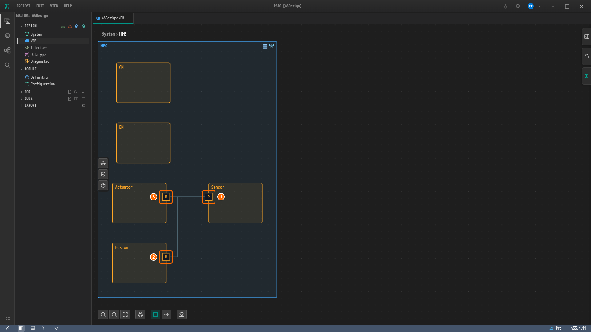
The composition HPC contains Sensor, Fusion, Actuator, CM and EM, and each node has the same NAME and AS PROTOTYPE.
All three ports are named Sensor with PORT INTERFACEService: Sensor, and the connectors Assembly_Sensor_Fusion and Assembly_Sensor_Actuator exist.
The EXECUTION tab of each AA Internal Behavior dialog has one process card, and there is no MachineFG : Off row anywhere.
The mapping boxes of Sensor, Fusion and Actuator are Sensor/AA/Sensor, Fusion/AA/Sensor and Actuator/AA/Sensor, and CLIENT ID is 0x2 for Fusion and 0x1 for Actuator.
The APPLICATION ID values in LOG CONFIG are SENS, FUSN, ACTA, CM and EM, and the first three have the DLT contexts SENS : INFO, FUSN : INFO and ACTA : INFO.
The VALIDATION panel shows No validation issues., and there is no badge next to the panel title or on the footer V icon.
The export folder has the five files AADesign_COM.arxml, AADesign_DataType.arxml, AADesign_Interface.arxml, AADesign_SWC.arxml and AADesign_System.arxml, and the status bar of the XML editor shows ✓ No problems.
No tab or dialog carries the modified mark ●.
Figure 14-1. The composition HPC of the finished design (Figure 8-12 in Adaptive Applications and Ports). The left column holds CM, EM, Actuator and Fusion from top to bottom, and Sensor is on the right. ① The P port of Sensor, ② the R port of Fusion, ③ the R port of Actuator. The positions of nodes and ports depend on the Auto Layout result and are not design values.
The 11 primitives (boolean, float32, float64, sint8, sint16, sint32, sint64, uint8, uint16, uint32, uint64) and the 2 pointer types VoidPtr and ConstVoidPtr are built-in types, so you do not enter them.
All five processes keep the defaults SCHEDULING POLICYSCHED_OTHER, SCHEDULING PRIORITY0, CPU USAGE0, MEM USAGE0B and TERMINATION BEHAVIORPROCESS-IS-NOT-SELF-TERMINATING. CORE AFFINITY is left unchecked. Create and save CM first, so that CM can be chosen in the EXECUTION DEPENDENCY of the other processes.
The DLT applications are gathered under the DLT ECU ECU1 entered in Configuring the Machine. APPLICATION DESCRIPTION and CONTEXT DESCRIPTION are left empty.
The files of a project finished through chapter 13 are listed below. The right column names the chapters that create or change each file.
AADesign/
├── AADesign.io.prj
├── design/
│   ├── DATATYPE.io.model                     Chapter 4
│   ├── INTERFACE.io.model                    Chapter 5
│   ├── IVC.io.model                          Chapters 1, 3, 7
│   ├── SERVICE.io.model                      Chapter 6
│   ├── SYSTEM.io.model                       Chapter 1
│   ├── VFB.io.model                          Chapters 1, 8
│   ├── Module/
│   │   └── Machine/
│   │       └── Ecu.machine.io.model          Chapters 1, 2
│   └── SWC/
│       ├── AdaptiveApplication/
│       │   ├── Actuator.swc.io.model         Chapters 8 to 11
│       │   ├── CM.swc.io.model               Chapters 8, 9, 11
│       │   ├── EM.swc.io.model               Chapters 8, 9, 11
│       │   ├── Fusion.swc.io.model           Chapters 8 to 11
│       │   └── Sensor.swc.io.model           Chapters 8 to 11
│       ├── Composition/
│       │   ├── HPC.swc.io.model              Chapters 1, 8
│       │   └── System.swc.io.model           Chapter 1
│       └── Layout/
│           ├── HPC.vfb.layout                Chapter 8
│           └── System.vfb.layout             Chapter 1
└── export/
    ├── AADesign_COM.arxml                    Chapter 13
    ├── AADesign_DataType.arxml               Chapter 13
    ├── AADesign_Interface.arxml              Chapter 13
    ├── AADesign_SWC.arxml                    Chapter 13
    └── AADesign_System.arxml                 Chapter 13
The machine file name Ecu.machine.io.model follows the name of the HPC node Ecu in the System editor. There is no field for the machine name.
A *.vfb.layout file holds only the view state, that is, the positions of nodes and ports. It is not exported to ARXML.
The project folder also has the folders doc, code, workflow and import. This tutorial does not use them.
In a project built by following the screens, saving in SOME/IP Deployment and Service Instances also creates design/SIGNAL.io.model and adds Sensor_SR and Sensor_CS to INTERFACE.io.model. These are Classic Platform elements that the Interface editor derives automatically from the SOME/IP deployment, and they are not part of the design this tutorial builds by hand.
Your export has the same design content as the reference design files EM_Test_*.arxml. The service interface, the SOME/IP deployment and instances, the service discovery configuration, the endpoints, the five Adaptive Applications and their ports, the connectors, the Executables, the startup configuration values of the Processes, the execution dependencies, the service instance mappings, the DLT applications and ECU, the data types and the system mapping are all the same. AADesign_Interface.arxml is byte-for-byte identical to EM_Test_Interface.arxml.
Reference design
Your export
Elements with a name (packages included)
245
289
Elements with the same path and the same values and references
204
204
Elements with the same path but different values or references
23
23
Elements moved to another package
6
6
Elements renamed in the same place
6
6
Elements only in the reference design
6
—
Elements only in your export
—
50
The differences are listed below. The line numbers and the reason for each element are in the section "How Your Export Differs from the Reference Files" of Exporting the ARXML.
The EM process is bound to MachineFG : Startup. The PROCESS EM of the export has one more FUNCTION-GROUP-STATE-IREF
The EM of the reference design has no function group state, but PAIO validation rejects that shape with The process "EM" declares no functionGroupState; at least one is required.
9, 12
ROOT SWC PROTOTYPE is AA for all five
In the reference design only CM and EM use RootSwComponent. Only the name differs; the design content is the same
9
An extra STATE-MANAGEMENT-MODULE-INSTANTIATIONSM (MAX-ACTION-LIST-DURATION1000)
The value entered to clear constr_10641. The reference design has no state management module
…/SENS/SENS becomes …/SENS/DltContext_0 (the same for FUSN and ACTA). The CONTEXT-ID values are unchanged
Machine package and name
MACHINEHPCMachine in the package /Machine/HPCMachine becomes Ecu and sits directly in the package /Machine, and the machine's function group and process mappings sit under /MachineConfig/Ecu. PAIO names the machine after the HPC node
Module name
LOG-AND-TRACE-INSTANTIATIONLog becomes LOG
System mapping name
SwMapping_HPC_to_HPC becomes SwMapping_HPC_to_Ecu
Resource groups
Instead of one shared RESOURCE-GROUPResourceGroup, each process gets its own group, Sensor_ResourceGroup … EM_ResourceGroup (CPU-USAGE0, MEM-USAGE0)
The type String
STD-CPP-IMPLEMENTATION-DATA-TYPE has an extra ARRAY-SIZE 256, and APPLICATION-PRIMITIVE-DATA-TYPE has an extra SW-TEXT-PROPS
Variable-size arrays
The CP-side mirrors IMPLEMENTATION-DATA-TYPEByteArray and String and the APPLICATION-ARRAY-DATA-TYPEByteArray come out in PAIO's variable-size array form: DYNAMIC-ARRAY-SIZE-PROFILE is VSA_LINEAR, and the array size sits on the element one level deeper. The sizes 1 and 256 are the same
The subscription timing of each consumer's event group, with the defaults left on the consumer cards. The event groups of the reference design refer to these two names, but the reference design does not define them
6
The function group MachineFG (Ecu_FunctionGroup) and 8 MODE-TRANSITION elements
The machine's default function group and its default transitions
1, 2
PROCESS-TO-MACHINE-MAPPING-SETEcu_ProcessToMachineMapping and five mappings
The result of the five processes being placed on the machine Ecu. They appear even without any core checked
9
The modules without values NM, TIME_SYNC, CRYPTO, IDSM, VUCM, UCM
Modules the machine configuration screen creates in advance
There is no field for it, so it becomes DltContext_0
The machine name and WAIT-FOR-SHUTDOWN1
The machine name follows the node name Ecu, and WAIT-FOR-SHUTDOWN does not appear in the export
REQUEST-TIMEOUT10, ALIVE-CHECK-INTERVAL0 and MAX-DATA-BYTES0 of the Communication Management module
The module screen offers only the sub-tabs ACCESS CONTROL and IPC and no field for these values, so the export has a CM-MODULE-INSTANTIATIONCM with only LOCAL-COM-ACCESS-CONTROL-ENABLEDfalse and REMOTE-ACCESS-CONTROL-ENABLEDfalse
The RESOURCE-GROUP-REF of a process
The OS value POSIX of the machine configuration screen is exported as the OS-MODULE-INSTANTIATION element, but the exporter writes this reference only when the machine's module list (the MODULE tab) has an OS module entry. The module list the machine configuration screen creates in advance has no OS module entry
The reference design splits the machine design into Ecu and an empty HPC. The tutorial attaches both to the one node Ecu
Reference paths of PROCESS
The execution dependency and function group state paths of the reference design cannot be found in its five files. Every path in your export can be found in the same file
FIBEX-ELEMENTS of SYSTEM
The 3 of the reference design (MACHINE-DESIGNEcu, MACHINE-DESIGNHPC, ETHERNET-CLUSTER) become 2 (MACHINE-DESIGNEcu, ETHERNET-CLUSTER). The missing one is the empty MACHINE-DESIGNHPC of the first row
CONTEXT-ROOT-SW-COMPONENT-PROTOTYPE-REF of the three service instance mappings
The reference design has /Executable/<name>/AA, one level short, which names no element. Your export has /Executable/<name>/<name>/AA, the root prototype AA of each Executable
MACHINE-DESIGN-REF of the MACHINE
The reference design has /System/VehicleTopology/Ecu/Ecu, which names no element in its five files. Your export points at the MACHINE-DESIGNEcu of the COM file (/System/MachineDesign/Ecu)