Adaptive Applications and Ports
What You Will Do
In this chapter you drill into the composition HPC created in Creating the Project and the HPC Machine in the VFB editor and create five Adaptive Applications.
You right-click inside the frame, create a node with Add SWC › Adaptive Application, and type the same name into NAME and AS PROTOTYPE — five times, for Sensor, Fusion, Actuator, CM and EM. Then you attach a P port to Sensor and R ports to Fusion and Actuator, and pick Sensor, created in The Service Interface, as the PORT INTERFACE of all three ports. Finally you connect the P port of Sensor to both R ports with Connect to, give the two connectors the names of the reference design, tidy the frame with Auto Layout and save.
When you finish this chapter, design/SWC/AdaptiveApplication/ holds five *.swc.io.model files, and design/SWC/Composition/HPC.swc.io.model holds five prototypes and the connectors Assembly_Sensor_Fusion and Assembly_Sensor_Actuator. In ARXML Export these become the reference design's five ADAPTIVE-APPLICATION-SW-COMPONENT-TYPE elements, one P-PORT-PROTOTYPE, two R-PORT-PROTOTYPE elements and two ASSEMBLY-SW-CONNECTOR elements.
Before You Begin
- Start from the state at the end of Binding Service Instances to the Connector.
design/SWC/contains onlyComposition/HPC.swc.io.model(no prototypes, no connectors),Composition/System.swc.io.modelandLayout/System.vfb.layout; the folderAdaptiveApplication/does not exist yet.design/INTERFACE.io.modelholds one service interface,Sensor. - The VALIDATION panel shows
No validation issues.. While you work, each new Adaptive Application adds one warning that stays until you save; saving removes them, so the chapter ends withNo validation issues.again. - You may close the
AADesign:Systemtab left open in chapter 7. This chapter starts by opening VFB from DESIGN in the EDITOR view.
The table below and the two connector names Assembly_Sensor_Fusion and Assembly_Sensor_Actuator are everything you type on the keyboard in this chapter. The five type names go into both NAME and AS PROTOTYPE, and all three port names are Sensor. Everything else is picked from menus and lists by clicking.
| Adaptive Application | NAME = AS PROTOTYPE | Port | Port NAME | PORT INTERFACE |
|---|---|---|---|---|
| Sensor | Sensor | one PPort | Sensor | Service: Sensor |
| Fusion | Fusion | one RPort | Sensor | Service: Sensor |
| Actuator | Actuator | one RPort | Sensor | Service: Sensor |
| Communication management | CM | none | — | — |
| Execution management | EM | none | — | — |
Drilling into the Composition HPC
Opening the VFB Editor and Drilling into HPC
-
In the EDITOR view on the left, click VFB under DESIGN. The tab
AADesign:VFBopens, and the root canvasSystemshows the single composition nodeHPC [Ecu]created in chapter 1. The machine icon at the right of its header shows that it is mapped to the HPC nodeEcuin the System editor. -
Double-click the node
HPC [Ecu]. The breadcrumb above the canvas changes toSystem > HPC, and the canvas shows one frame,HPC. The frame is empty. -
Click the title
HPCat the top left of the frame header to select the frame. Its border brightens, eight small resize handles appear at the corners and the middles of the sides, and the COMPOSITION panel opens on the right. It shows NAMEHPC, AS PROTOTYPEHPC, DESCRIPTION, PORTS (No ports available) and PORT GROUPS (No port groups). -
Drag the handle at the bottom-right corner down and to the right to widen the frame. From the default size of 600×400, about 900×520 is enough. The tab
AADesign:VFBgets the modified mark ●.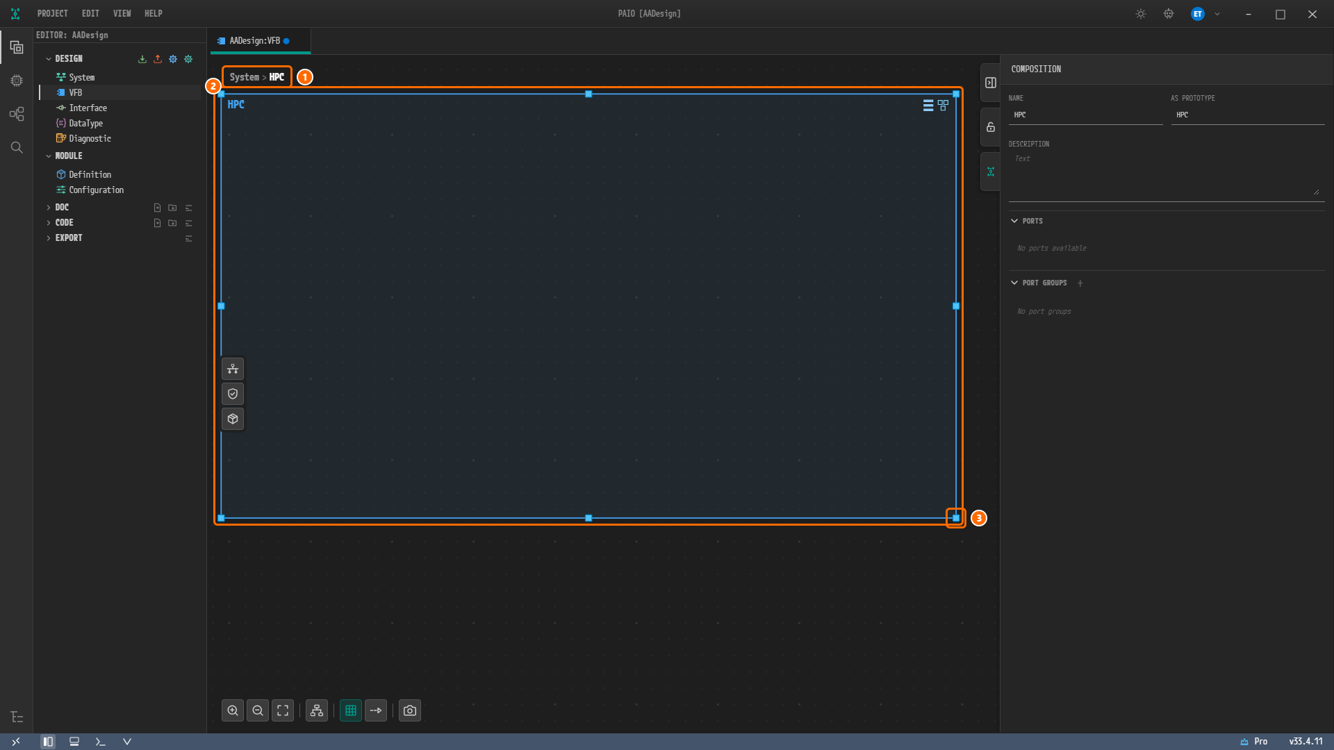
Figure 8-1. The VFB editor after drilling into the composition
HPCand widening the frame. ① The breadcrumbSystem > HPC, ② the widened empty frameHPC(selected, with its eight resize handles), ③ the resize handle at the bottom-right corner. The COMPOSITION panel on the right shows NAMEHPCand AS PROTOTYPEHPC. The footer has no validation badge yet.
Note. The frame does not grow by itself when you put nodes into it. With five 160×120 nodes in the default 600×400 frame, the ports touch each other and the connector lines are hard to click later. The widened size has no effect on the design values, and Auto Layout later sets the frame size again.
Creating the Adaptive Application Sensor
Of the five, Sensor is shown as a procedure. Creating the node and typing the two fields NAME and AS PROTOTYPE is the same for the other four.
Adding an Adaptive Application inside the Frame
-
Right-click an empty spot inside the frame
HPC(top left). A five-line menu opens: Add SWC, Attach SWC, Add Port, Add Composition, Attach Composition. Right-clicking the empty canvas outside the frame opens no menu. -
Hover over Add SWC. A seven-line submenu opens: Composition, Adaptive Application, Application, Complex Device Driver, Ecu Abstraction, Sensor Actuator, Service.
-
Click Adaptive Application. The node
AdaptiveApp_0appears with its top-left corner at the point you right-clicked.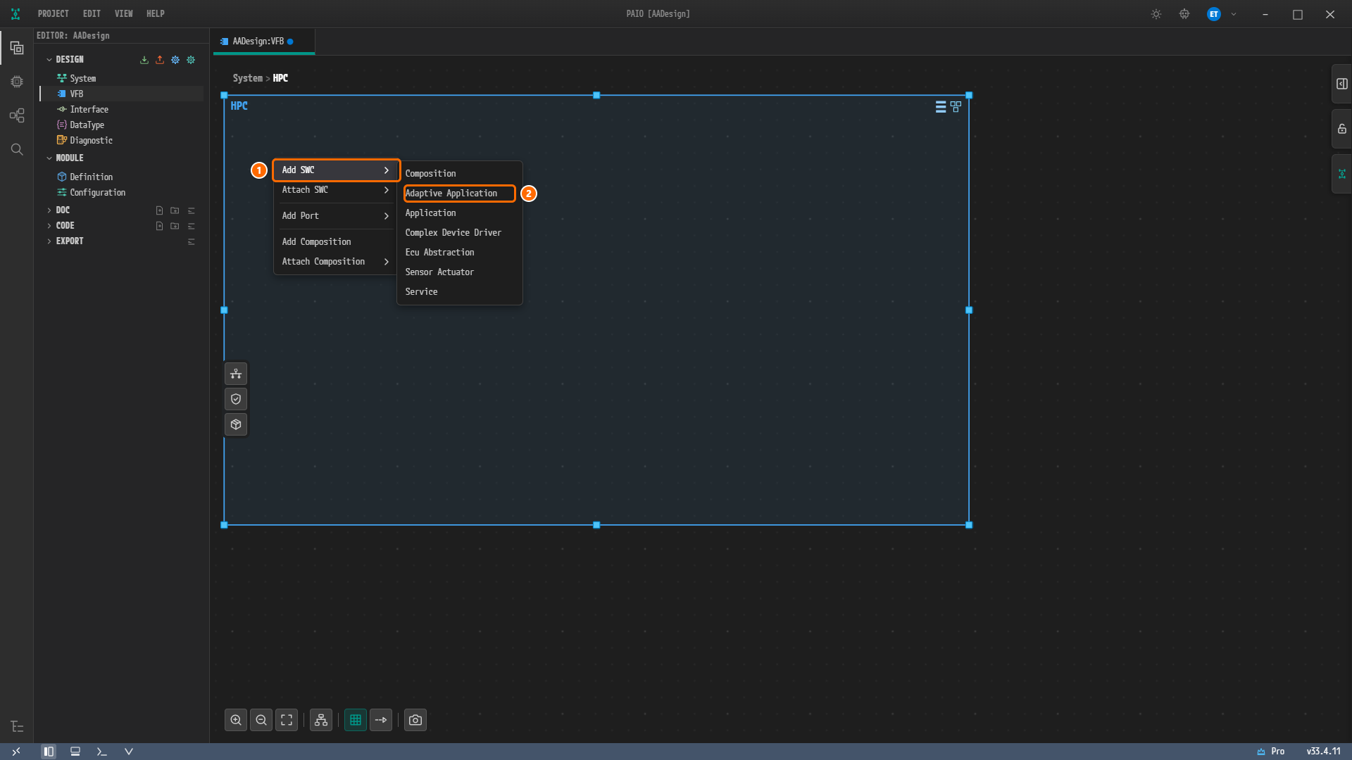
Figure 8-2. The menu after right-clicking inside the frame
HPC. ① Add SWC, ② Adaptive Application in the submenu. Of the seven submenu items, this chapter uses only Adaptive Application. Application is the atomic software component of the Classic Platform and is not used in this tutorial.
Checking the New Node and the Properties Panel
-
Click the header
AdaptiveApp_0of the new node. The node border brightens, eight resize handles appear, and the ADAPTIVE APPLICATION panel opens on the right. -
Check the fields of the panel: NAME
AdaptiveApp_0, AS PROTOTYPEAdaptiveApp_0_0, DESCRIPTION (hintText), and below them the section PORTS showingNo ports available.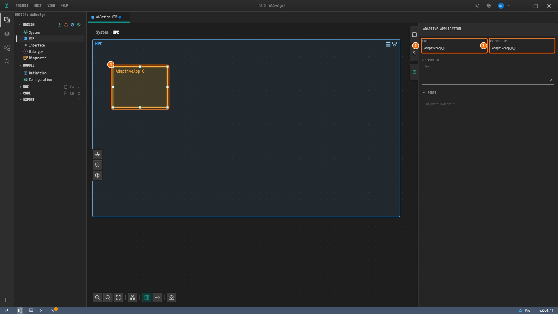
Figure 8-3. The new node and the ADAPTIVE APPLICATION panel. ① The node
AdaptiveApp_0(selected), ② NAME =AdaptiveApp_0, ③ AS PROTOTYPE =AdaptiveApp_0_0. The PORTS section showsNo ports available, and the validation badge in the footer is1.
NAME is the name of the Adaptive Application type and is used as the node label on the canvas. AS PROTOTYPE is the name of the prototype of that type placed inside the composition HPC. The reference design uses the same name for both, so you type the same value into both fields.
Typing the Name and the Prototype Name
-
Click the NAME field, delete
AdaptiveApp_0, typeSensorand pressTab. The node label on the canvas changes toSensor. AS PROTOTYPE does not follow and staysAdaptiveApp_0_0. -
Click the AS PROTOTYPE field, delete
AdaptiveApp_0_0, typeSensorand pressTab.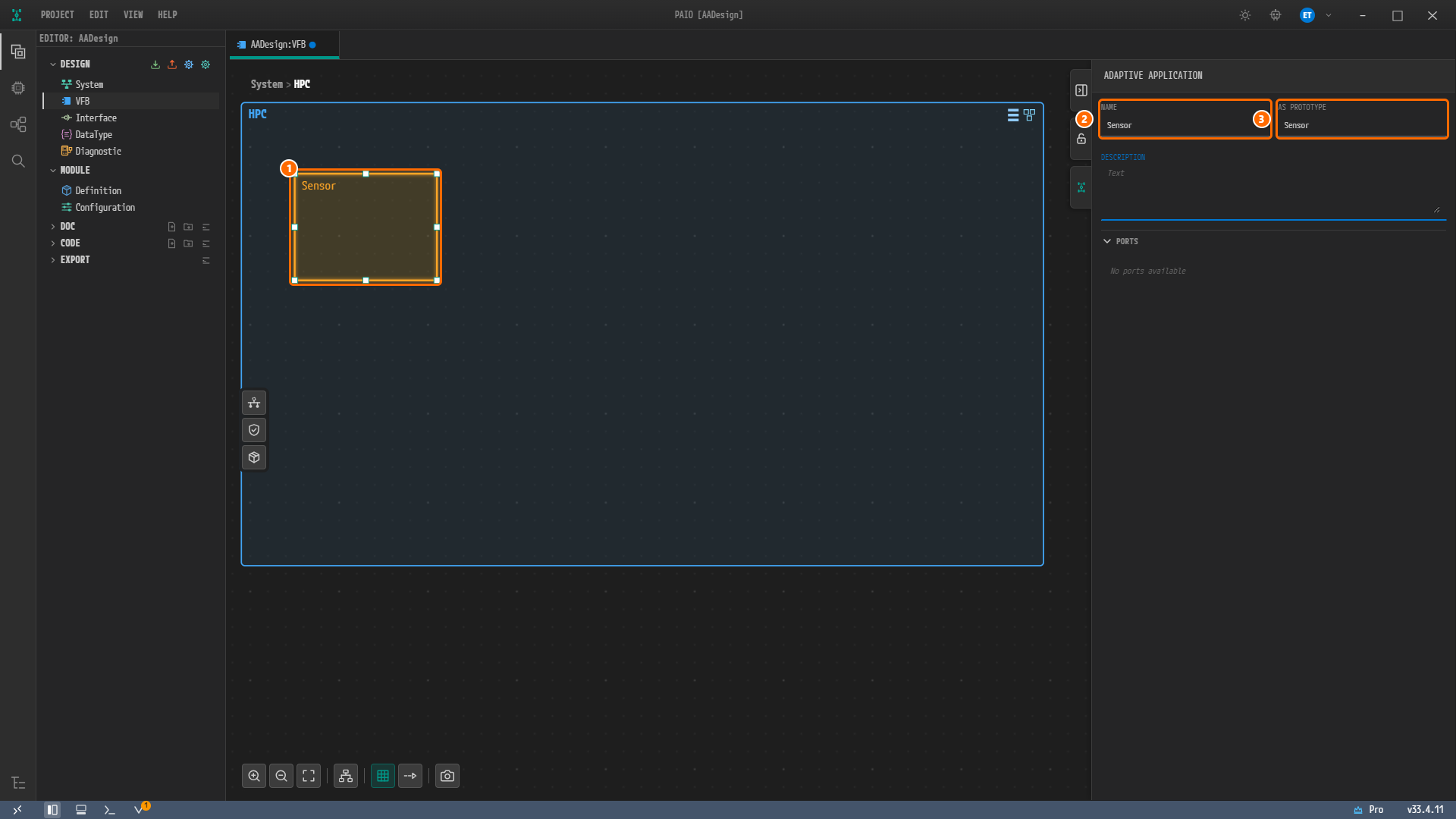
Figure 8-4. The screen after typing both fields. ① The node whose label changed to
Sensor, ② NAME =Sensor, ③ AS PROTOTYPE =Sensor.
Note. Changing NAME does not change AS PROTOTYPE. For all five nodes you must type both fields separately. After you rename the previous node, the next new node again gets the default names
AdaptiveApp_0/AdaptiveApp_0_0.
Creating the Other Four Adaptive Applications
Create Fusion, Actuator, CM and EM the same way. Only the spot you right-click differs. Putting Sensor, Fusion and Actuator in the top row from left to right and CM and EM in the bottom row gives the shape shown in the following figures.
| Order | Spot to right-click | NAME | AS PROTOTYPE |
|---|---|---|---|
| 2 | top row, right of Sensor | Fusion | Fusion |
| 3 | top row, right of Fusion | Actuator | Actuator |
| 4 | bottom row, left | CM | CM |
| 5 | bottom row, right of CM | EM | EM |
-
Right-click an empty spot inside the frame and click Add SWC › Adaptive Application.
-
Click the header of the new node, type the name from the table into NAME and press
Tab, then type the same name into AS PROTOTYPE and pressTab. -
Finish all four rows of the table. The frame holds five nodes, with no ports and no lines yet.
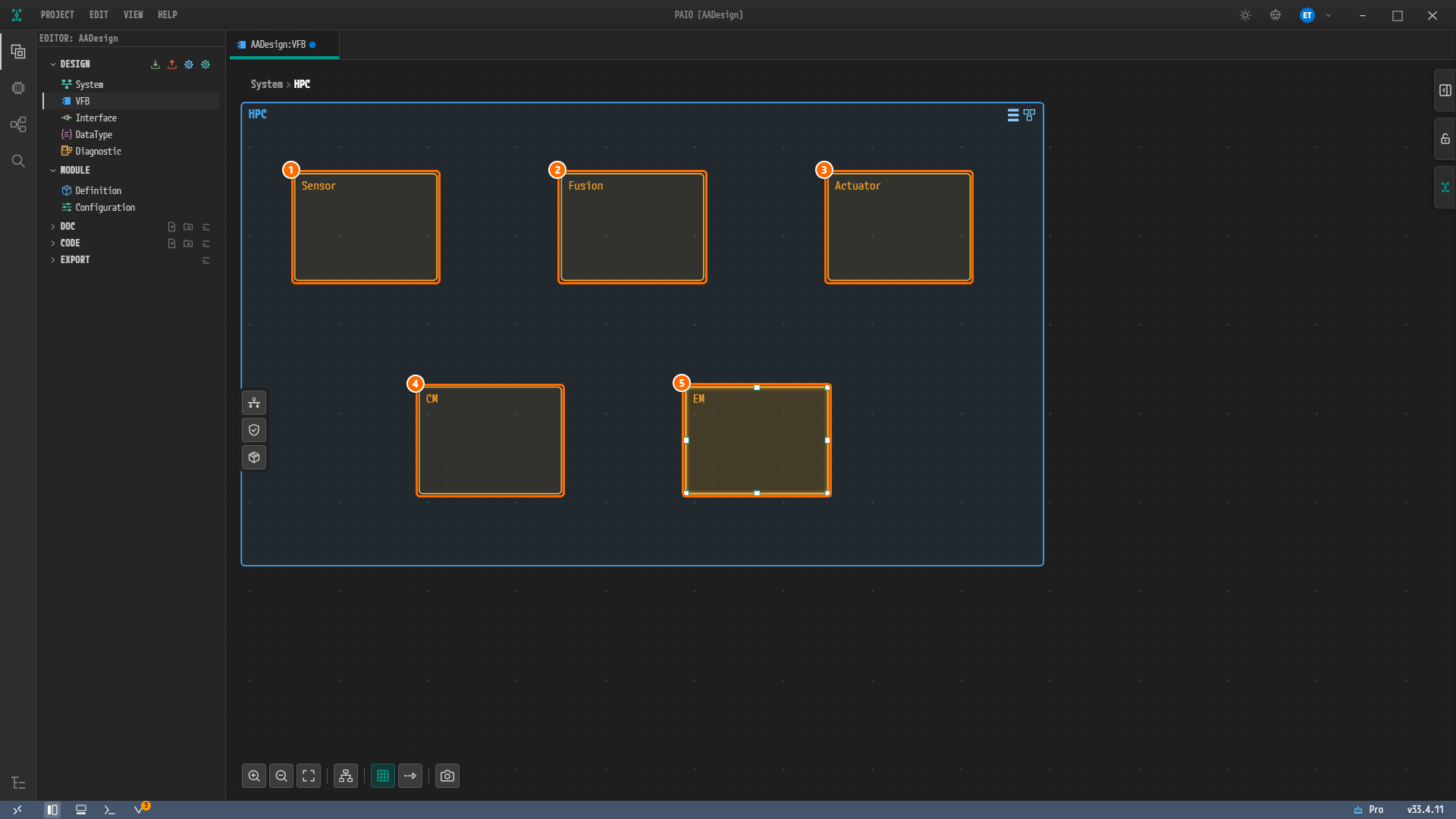
Figure 8-5. The frame
HPCafter creating all five. ①Sensor, ②Fusion, ③Actuator(top row), ④CM, ⑤EM(bottom row; created last and therefore selected). The validation badge in the footer is5.
Creating them in the order Sensor, Fusion, Actuator, CM, EM gives the prototype list in the saved file the same order. Creating them in another order yields the same design content.
Attaching the P Port to Sensor
Of the three ports, the P port of Sensor is shown as a procedure. A port is created by right-clicking near the node border, and its name and interface are set in the properties panel.
Creating a PPort with Add Port
-
Right-click near the right edge of the node
Sensor(inside the node). The nodeSensoris selected, and a three-line node menu opens: Add Port, Detach SWC, Delete. -
Hover over Add Port. The submenu PPort, RPort, PRPort opens.
-
Click PPort. A port with a
Picon appears on the side nearest to the point you right-clicked, that is, on the right side of the node. Its default name isPPort_0.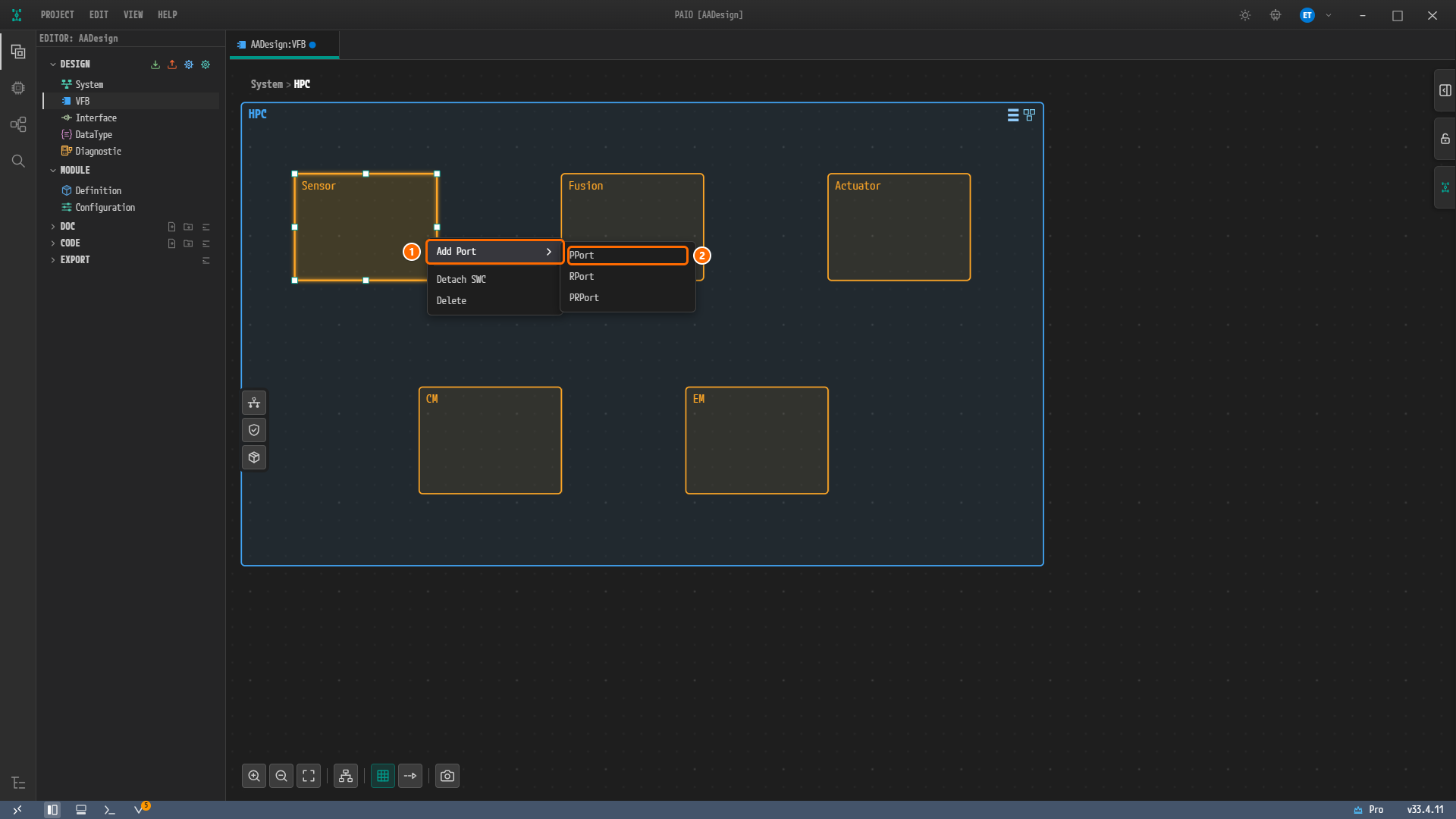
Figure 8-6. The menu after right-clicking the right edge of the node
Sensor. ① Add Port, ② PPort in the submenu. The port is created on the side nearest to the right-clicked point, at that height.
Typing the Name and Picking the PORT INTERFACE
-
Click the new
Picon. The PPORT panel opens on the right and shows NAMEPPort_0and PORT INTERFACE. PORT INTERFACE is empty, and its label and the messagePort Interface is requiredbelow it are red. -
Type
Sensorinto the NAME field and pressTab. The name labelSensorappears next to the icon on the canvas. -
Click the PORT INTERFACE field. The field shows the search hint
Type to search..., and a list opens with a single entry,Service: Sensor. A port of an Adaptive Application is offered only service interfaces and Adaptive Platform interfaces, and the only one in this project is the service interface created in chapter 5.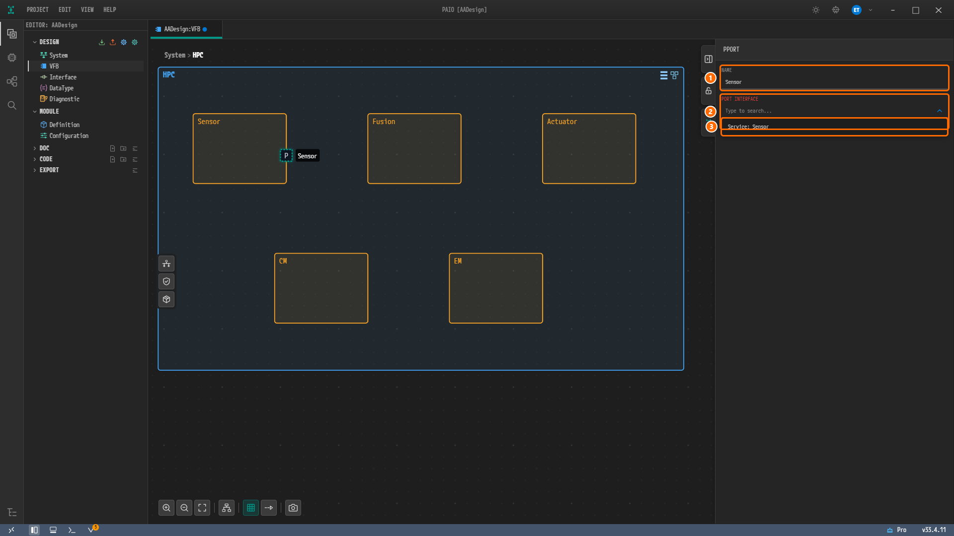
Figure 8-7. The PPORT panel of the P port. ① NAME =
Sensor, ② the PORT INTERFACE field (hintType to search...), ③ the only list entry,Service: Sensor. The label PORT INTERFACE stays red until an interface is picked. The name labelSensoris visible next to thePicon on the canvas.
Checking the Result
-
Click
Service: Sensorin the list. The PORT INTERFACE field showsService: Sensor, with clear × and expand ˅ at its right, and its label is no longer red. -
The section SERVICE COMSPEC appears below in the panel. The EVENTS row is
ByteArraySensorDataQUEUED-SENDER, and the METHODS row isCalculationSERVER.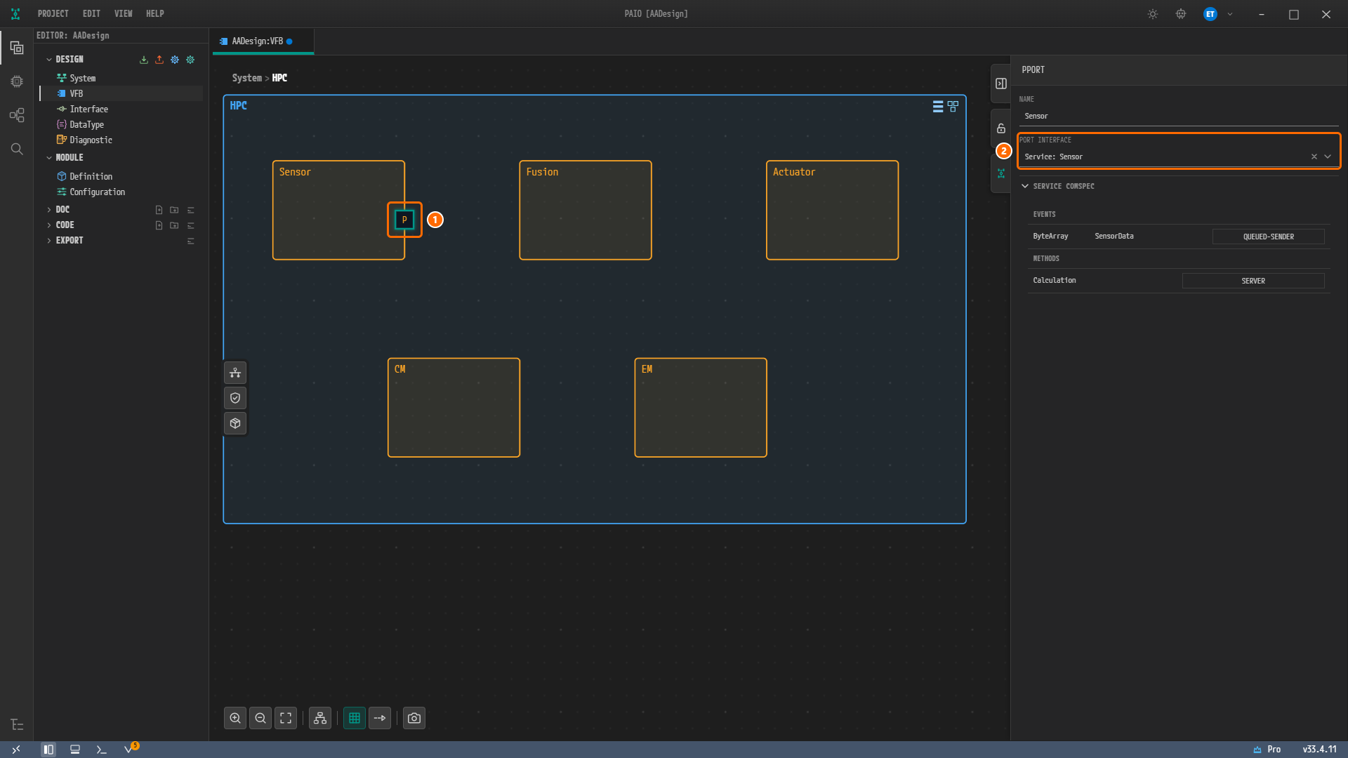
Figure 8-8. The PPORT panel after picking the interface. ① The
Picon on the right side of the nodeSensor(selected), ② PORT INTERFACE =Service: Sensor. The SERVICE COMSPEC section below shows EVENTSByteArraySensorDataQUEUED-SENDER and METHODSCalculationSERVER.
SERVICE COMSPEC shows the events and methods of the chosen interface in the role of this port. Because it is a P port, the event SensorData is on the sending side (QUEUED-SENDER) and the method Calculation is the server (SERVER). This chapter does not change any value in this section.
Attaching the R Ports to Fusion and Actuator
Attach R ports to the two consumers the same way. What differs is picking RPort in the menu and the side you right-click.
| Node | Spot to right-click | Menu | Default name | NAME | PORT INTERFACE |
|---|---|---|---|---|---|
Fusion | near the left edge | Add Port › RPort | RPort_0 | Sensor | Service: Sensor |
Actuator | near the left edge | Add Port › RPort | RPort_0 | Sensor | Service: Sensor |
-
Right-click near the left edge of the node
Fusionand click Add Port › RPort. A portRPort_0with anRicon appears on the left side of the node. -
Click the
Ricon. The RPORT panel opens. TypeSensorinto NAME and pressTab, then click the PORT INTERFACE field and clickService: Sensor. The SERVICE COMSPEC section appears below in the panel. -
Repeat steps 1 and 2 for the node
Actuator.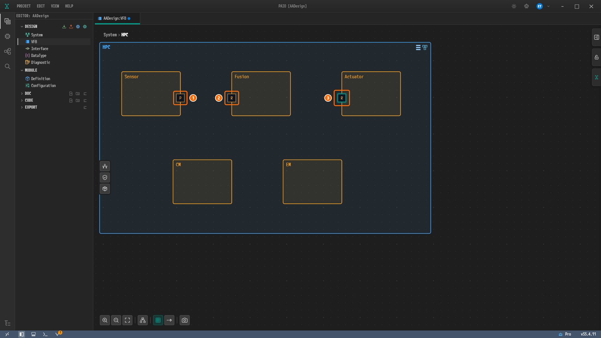
Figure 8-9. The frame
HPCafter creating all three ports. ①Pon the right side ofSensor, ②Ron the left side ofFusion, ③Ron the left side ofActuator(selected). There are no connector lines yet.
Connecting the Ports
A connector starts at the providing port. From the single P port of Sensor you draw lines to the two R ports of Fusion and Actuator.
Connecting to Both R Ports with Connect to
-
Right-click the
Picon of the nodeSensor. A three-line port menu opens: Connect to, Connect to Mapping, Delete. -
Hover over Connect to. The submenu shows two entries,
[A] Fusion / Sensorand[A] Actuator / Sensor.[A]means an assembly connector, and the rest isnode label / port. Only ports of the opposite direction using the same interface are offered.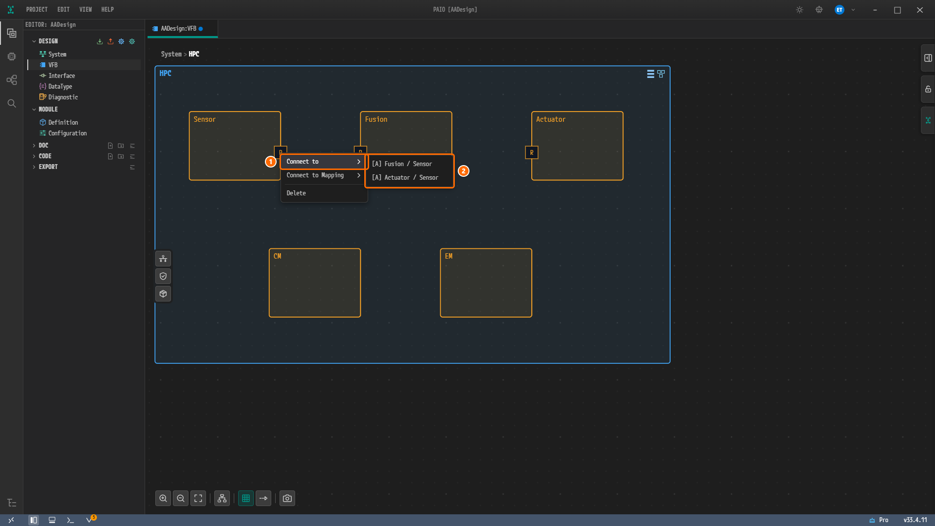
Figure 8-10. The menu after right-clicking the P port of
Sensor. ① Connect to, ② the candidate list[A] Fusion / Sensor,[A] Actuator / Sensor. -
Click
[A] Fusion / Sensor. One line appears from the P port ofSensorto the R port ofFusion. -
Right-click the same
Picon again and hover over Connect to.Fusion, already connected, is gone, and only[A] Actuator / Sensorremains. Click it. There are now two lines.
Renaming the Connectors
-
Click the line from
SensortoFusion. The two lines overlap near the P port, so click a non-overlapping stretch close to the R port ofFusion. The line turns cyan and both end ports are highlighted. -
The ASSEMBLY panel opens on the right, and NAME in the BASIC INFO section is
Assembly_Sensor_Sensor_Fusion_Sensor. Click the field, replace the name withAssembly_Sensor_Fusion, the name in the reference design, and pressEnter. -
Click the line from
SensortoActuatortoo, for example on the stretch that runs aboveFusion. Its NAME isAssembly_Sensor_Sensor_Actuator_Sensor; change it toAssembly_Sensor_Actuatorthe same way and pressEnter.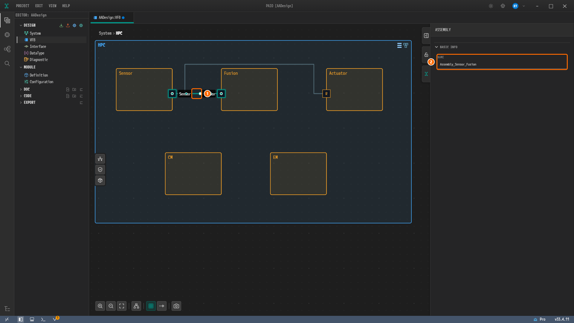
Figure 8-11. The screen with the line
Sensor→Fusionselected, after renaming. ① The clicked point on the line, ② NAME =Assembly_Sensor_Fusionunder BASIC INFO in the ASSEMBLY panel. The other line leaves the P port ofSensor, goes around the top and enters theRofActuator.
Note. The editor names a new assembly connector
Assembly_<provider prototype>_<provider port>_<requester prototype>_<requester port>, so that the name stays unique even when two prototypes are joined by more than one port pair. The reference design names its connectors after the two prototypes only, so you shorten both names.
Tidying with Auto Layout and Saving
-
In the toolbar below the canvas, click the fourth button, Auto Layout (hierarchy icon). A progress dialog appears briefly, and the five nodes and two lines are rearranged. Ports may move to the opposite side.
-
Click an empty spot on the canvas to clear the selection.
-
Press
Ctrl+S. The modified mark ● on the tabAADesign:VFBdisappears, and so does the validation badge in the footer.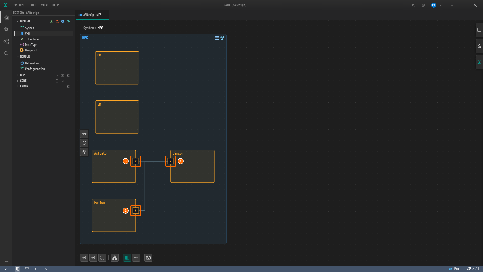
Figure 8-12. The frame
HPCafter Auto Layout and saving. The left column holds, from the top,CM,EM,ActuatorandFusion, andSensoris on the right. ① The P port ofSensor(moved to the left side), ② the R port ofFusion, ③ the R port ofActuator(both moved to the right side). The tab has no modified mark ● and the footer has no validation badge.
Note. The shape produced by Auto Layout may differ slightly from the figure. Node positions, the frame size and the side a port sits on are view state stored only in
design/SWC/Layout/HPC.vfb.layout; they are not design values and are not exported to ARXML.
Saving creates five files in design/SWC/AdaptiveApplication/: Sensor.swc.io.model, Fusion.swc.io.model, Actuator.swc.io.model, CM.swc.io.model and EM.swc.io.model. The port of Sensor.swc.io.model looks as follows; Fusion and Actuator have direction required, and CM and EM have ports [].
"name": "Sensor",
"type": "adaptive-application",
"ports": [
  { "name": "Sensor", "direction": "provided", "port-interface": "Sensor", "port-interface-category": "service" }
]
design/SWC/Composition/HPC.swc.io.model gains prototypes and connectors. The HPC entry of design/VFB.io.model gets the same five prototypes; the connectors are not written there.
"prototypes": [
  { "name": "Sensor",   "swc-ref": "AdaptiveApplication/Sensor" },
  { "name": "Fusion",   "swc-ref": "AdaptiveApplication/Fusion" },
  { "name": "Actuator", "swc-ref": "AdaptiveApplication/Actuator" },
  { "name": "CM",       "swc-ref": "AdaptiveApplication/CM" },
  { "name": "EM",       "swc-ref": "AdaptiveApplication/EM" }
],
"connectors": [
  { "name": "Assembly_Sensor_Fusion",   "category": "assembly",
    "provider": { "prototype": "Sensor", "port": "Sensor" }, "requester": { "prototype": "Fusion",   "port": "Sensor" } },
  { "name": "Assembly_Sensor_Actuator", "category": "assembly",
    "provider": { "prototype": "Sensor", "port": "Sensor" }, "requester": { "prototype": "Actuator", "port": "Sensor" } }
]
design/INTERFACE.io.model does not change, and design/SIGNAL.io.model is not created in this chapter.
Viewing the Validation Result
-
Look at the V icon in the footer at the bottom of the window, the fifth icon from the left. It carries no badge, but its tooltip still reads
Validation: 0 error(s), 5 warning(s), 0 info(s), the last non-zero count; the VALIDATION panel shows the current result. -
Look at the VALIDATION panel. If it is closed, click the V icon in the footer. Under the column headers ELEMENT TYPE, NAME, DESCRIPTION and CONSTR there is no row for anything created in this chapter:
Sensor,Fusion,Actuator,CM,EM, the portSensor,Assembly_Sensor_Fusion,Assembly_Sensor_ActuatororHPC.
Figure 8-13. The VALIDATION panel after saving. The header has no badge and the body shows
No validation issues..
Note. While you edit, the V icon in the footer carries an orange badge that counts warnings. It reads
1after the first Adaptive Application, grows by one with each new one to5, and stays5while you add the ports and connectors. Each warning is a row with ELEMENT TYPESwComponentPrototype, an empty CONSTR and a DESCRIPTION such asPrototype "Sensor" in "HPC": referenced SW component "AdaptiveApplication/Sensor" not found., because the files of the new Adaptive Applications are written only when you save.Ctrl+Sclears all five. Ignore the badge before saving.
Why Is It Designed This Way?
- The five Adaptive Applications are the five
ADAPTIVE-APPLICATION-SW-COMPONENT-TYPEelements of the reference design. The reference design hasSensor,Fusion,Actuator,CMandEMunder/SwComponentType/AdaptiveApplication/.CMandEMhave no ports. - The prototype name equals the type name. The composition
HPCof the reference design has fiveSW-COMPONENT-PROTOTYPEelements, each named like its type. That is why you type the same value into AS PROTOTYPE as into NAME. - All three ports are named
Sensor. In the reference design,P-PORT-PROTOTYPE Sensor/Sensor,R-PORT-PROTOTYPE Fusion/SensorandActuator/Sensorcarry the name of the interface. All three point to/PortInterface/Service/SensorthroughPROVIDED-INTERFACE-TREForREQUIRED-INTERFACE-TREF. - One provider, two consumers. The reference design has two
ASSEMBLY-SW-CONNECTORelements,Assembly_Sensor_FusionandAssembly_Sensor_Actuator, and thePROVIDER-IREFof both is the portSensorofHPC/Sensor. It is a fan-out fromSensorto two consumers, not a chain fromSensorthroughFusiontoActuator. - The connector names are typed. The default names given by the editor also carry the port names (
Assembly_Sensor_Sensor_Fusion_Sensor), while the reference design names its twoASSEMBLY-SW-CONNECTORelements after the prototypes only (Assembly_Sensor_Fusion,Assembly_Sensor_Actuator). - Layout is not design. The ports of the reference design carry no coordinates. Node and port positions are stored only in
HPC.vfb.layoutand are not exported to ARXML.
Checklist
- The breadcrumb is
System > HPC, and the frameHPCholds the five nodesSensor,Fusion,Actuator,CMandEM. - Clicking each node shows the same name in NAME and AS PROTOTYPE of the ADAPTIVE APPLICATION panel.
-
Sensorhas onePport,FusionandActuatorhave oneRport each, and PORTS ofCMandEMshowsNo ports available. - All three ports have NAME
Sensor, PORT INTERFACEService: Sensorand a SERVICE COMSPEC section. - There are two lines, and clicking them shows NAME
Assembly_Sensor_FusionandAssembly_Sensor_Actuatorrespectively in the ASSEMBLY panel. - The tab
AADesign:VFBhas no modified mark ●. -
design/SWC/AdaptiveApplication/holds five*.swc.io.modelfiles. - The VALIDATION panel shows
No validation issues.and the header carries no badge.
Next Step
In Executables and Processes, you create an Executable and a Process for each of the five Adaptive Applications.