VFB Editor
What This Chapter Covers
This chapter explains how to use the VFB editor: from the Virtual Functional Bus point of view you place software components (SWC) and compositions, then connect ports. It covers canvas operations, the complete list of context menus, the properties panel, and four detail dialogs. Among the detail dialogs, SWC Internal Behavior and AA Internal Behavior open when you double-click a node, while Machine Configuration and ECU Configuration open when you click the mapping icon in the header of a composition node.
This chapter is for users who design the software architecture of the AUTOSAR Classic or Adaptive platform. A project must be open before you start. It helps to define the interfaces you will assign to ports in advance in 09. Interface Editor. To use ECU/HPC mapping, nodes must already exist in 06. IVC Editor.
In the project Explorer, open design ▸ System ▸ VFB and the editor opens in a tab.
8.1 Files Written on Save
The VFB editor writes several files together in a single save. The files are the following.
| File | Contents |
|---|---|
| VFB model | The composition list (name · description · boundary ports · prototypes) and the InterfaceMapping list |
| SWC definition | The definition of one SWC (ports, connectors, internal behavior, AP mappings) |
design/SWC/Layout/<Composition>.vfb.layout | The canvas arrangement of one composition |
| Machine configuration | The Adaptive Machine configuration |
Connectors are stored in the composition's SWC definition, not in the VFB model. A composition entry in the VFB model holds only the name, description, boundary ports, and prototype references.
A .vfb.layout file is a project-internal file that holds only the screen arrangement — node
positions, sizes, port positions, and connection routes. This information is not written to ARXML,
and it is not restored on import either (an import generates new node positions).
The kind folder name is fixed per SWC kind, as follows.
| SWC kind | Folder name |
|---|---|
| Composition | Composition |
| Application | Application |
| Adaptive Application | AdaptiveApplication |
| Complex Device Driver | ComplexDeviceDriver |
| Service | Service |
| Ecu Abstraction | EcuAbstraction |
| Sensor Actuator | SensorActuator |
The old file of a renamed SWC is deleted when you save. Until you save, the file with the old name stays on disk. So if the file list looks wrong after a rename, save with
Ctrl+Sfirst.
8.2 SWC Kinds
The ADD SWC menu offers seven kinds.
| Menu label | Description |
|---|---|
| Composition | A composition (a container that holds other SWCs) |
| Adaptive Application | An Adaptive Platform application |
| Application | A Classic application SWC |
| Complex Device Driver | A complex device driver |
| Ecu Abstraction | An ECU abstraction SWC |
| Sensor Actuator | A sensor/actuator SWC |
| Service | A BSW service SWC |
An InterfaceMapping node is not an SWC kind. You can create it only with ADD INTERFACE MAPPING, which appears when you right-click the empty canvas at the root level. It is a separate node, and its only role is to link an AP service interface to CP SR/CS interfaces (see 8.7).
8.3 Canvas Operations
This section lists the mouse and keyboard operations and the toolbar buttons you use on the canvas.
Mouse
The mouse operations are the following.
| Operation | Behavior |
|---|---|
| Left-click drag on empty space | Pan the view |
| Middle-button drag | Pan the view |
Space + left-click drag | Pan the view |
| Mouse wheel | Scroll the view up and down (the same direction as a document scroll) |
Shift + wheel | Scroll the view left and right |
Ctrl + wheel | Zoom (0.1x to 4.0x, 1.0x by default) |
| Click a node | Selects it. Eight resize handles appear on the selection |
Ctrl + click | Toggle multi-selection (both nodes and connections) |
| Drag a node | Move |
| Drag a resize handle | Resize |
Shift + drag from a port | Connection mode (see 8.6) |
| Double-click a composition | Drill down (enter that composition) |
| Double-click Application / Complex Device Driver / Service / Ecu Abstraction / Sensor Actuator | The SWC Internal Behavior dialog (8.8) |
| Double-click Adaptive Application | The AA Internal Behavior dialog (8.9) |
| Right-click | Context menu (8.5) |
Keyboard
The keys you can use on the canvas are the following.
| Key | Behavior |
|---|---|
Ctrl+S | Save |
Ctrl+Z | Undo |
Ctrl+Y / Ctrl+Shift+Z | Redo |
Esc | Cancels only the waypoint drag if one is in progress; otherwise clears the selection |
Some keys do not work on the canvas.
Delete/Backspace,Ctrl+A,Ctrl+C/Ctrl+V/Ctrl+X, the arrow keys,Ctrl+Shift+S, andCtrl+Odo nothing on the VFB canvas. In particular, you delete a node or a port with DELETE in the right-click menu, not with theDeletekey. Note thatDelete/Backspacedo work inside the detail dialogs of 8.8 and 8.9.
Toolbar Buttons (Bottom Left of the Canvas)
Each toolbar button behaves as follows.
| Button | Behavior |
|---|---|
| Zoom In / Zoom Out | Zoom in / zoom out. At the limit the button dims and stops responding |
| Fit to View | Fits the whole content into view |
| Auto Layout | Automatic layout (elkjs based; see the description below) |
| Toggle Grid | Toggles the grid (on by default) |
| Toggle Connector Animation | Toggles the flow animation on connections (off by default) |
| Export as PNG | Saves the current diagram as a PNG |
Export as PNG saves into the doc/capture/ folder inside the project, named
YYYYMMDD_HHMMSS_NNN.png (NNN is a three-digit serial number that continues from the existing
files in the folder). If the canvas is empty, a No content to export warning toast appears and
nothing is saved.
Auto Layout clears every connection route you adjusted by hand. If at least one such route
exists, a confirmation dialog appears first — the title is Auto Layout, the body is
N manually adjusted connector route(s) will be replaced by the automatic layout., and the buttons
are Replace / Cancel. While it runs, a progress dialog that you can cancel is shown.
8.4 The Root Level and Drill-Down
VFB has two level concepts.
- Root level — you have not entered any composition. Top-level compositions and InterfaceMapping nodes are placed here.
- Drilled-down state — you have entered one composition. That composition is drawn as a frame and its child nodes are placed inside the frame.
Double-click a composition to drill into it. Double-clicking the composition you are already in (the active one) does nothing.
When you drill down, a breadcrumb appears at the top left of the canvas and shows your position
in the form SystemName > Composition > .... Click an earlier entry to return to that level. The
last entry is your current position, so it is bold and not clickable. At the root level the
breadcrumb is hidden and an SVG system label is shown instead.
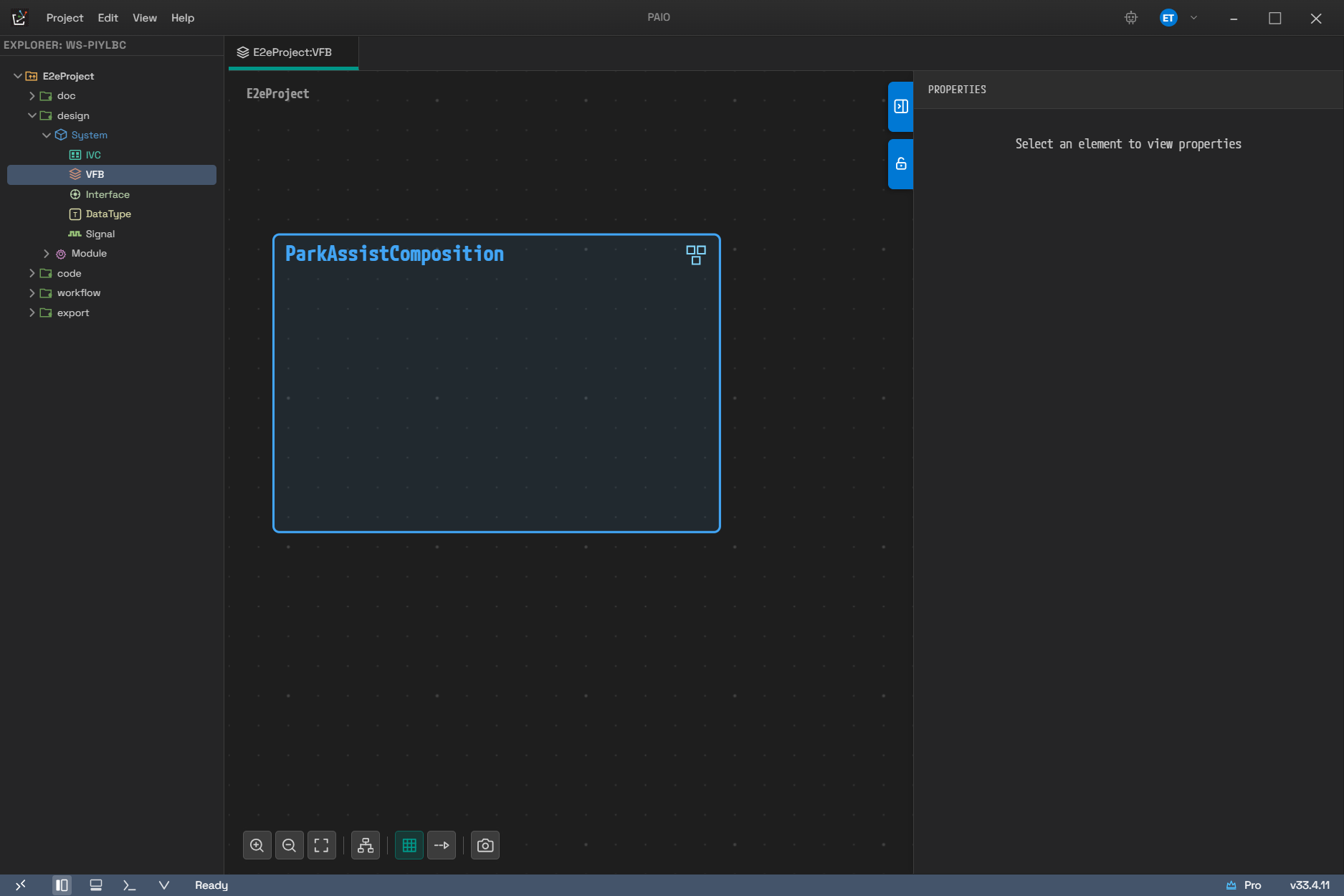
The root level. Only one top-level composition, ParkAssistComposition, is placed, and the system label (E2eProject) appears where the breadcrumb would be.
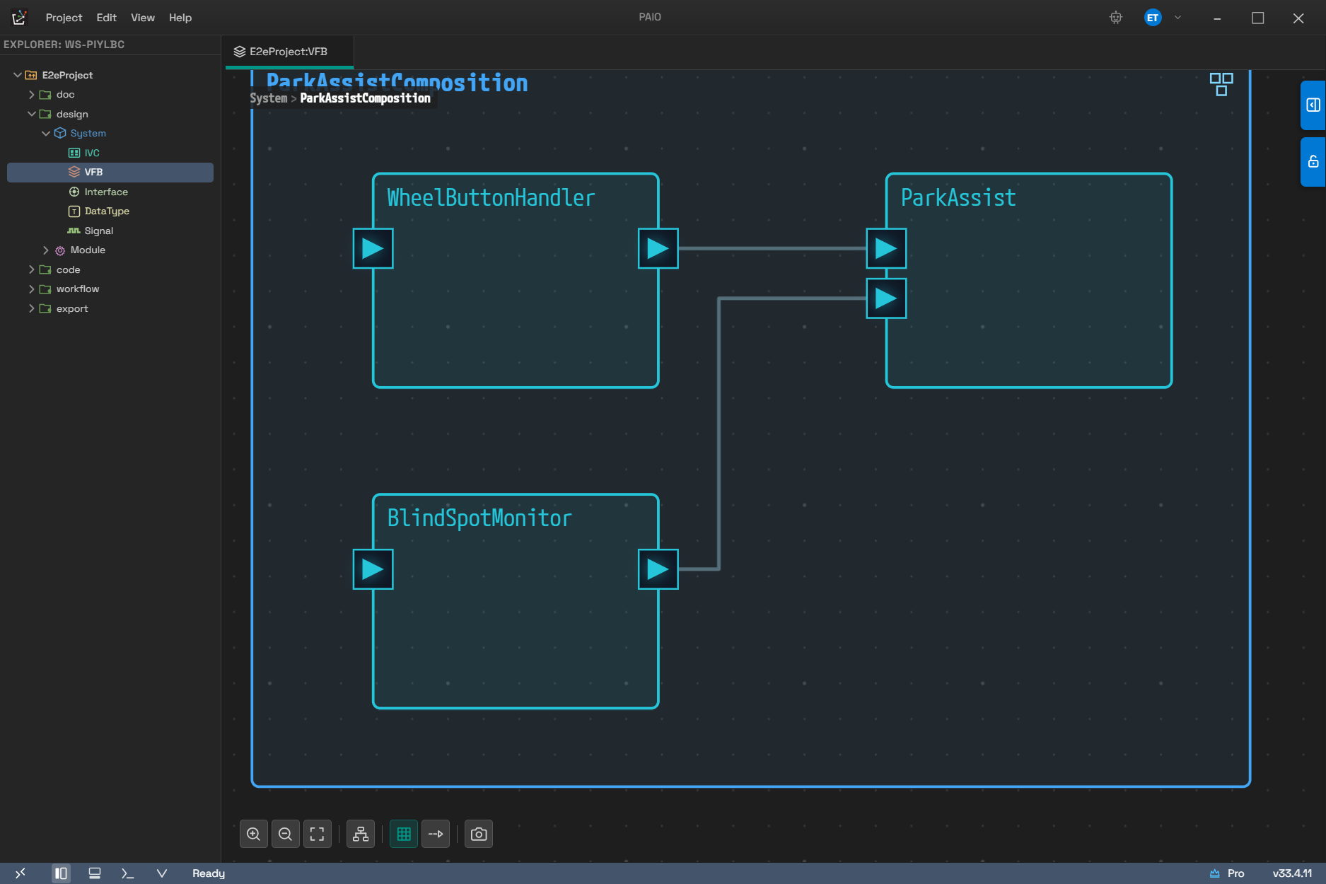
The same composition after double-clicking to drill into it. The composition turns into a frame and its three child SWCs are placed inside it. The label at the top left changes to the breadcrumb System > ParkAssistComposition.
Right-clicking the empty canvas outside the frame while drilled down shows no menu. The empty canvas looks like it is at the same level as the open composition, but a node created there would go under that composition and create an illusion about the level. When you create a node while drilled down, always right-click the frame (the composition).
8.5 Context Menus
The context menu is made up differently depending on what you right-click. This section lists the menu items per target.
8.5.1 Empty Canvas (Root Level Only)
Right-clicking the empty canvas at the root level shows the following menu.
| Item | Behavior |
|---|---|
| ADD COMPOSITION | Adds a new composition |
| ATTACH COMPOSITION | Attaches an already defined composition as a prototype |
| ADD INTERFACE MAPPING | Adds an InterfaceMapping node |
The ATTACH COMPOSITION submenu offers both the compositions loaded in the diagram and the
compositions that exist only on disk (not placed yet) as candidates. At the root level the root
composition itself is excluded. While drilled down, the current composition, its ancestor
compositions, compositions that are already children, and compositions that would create a circular
reference are excluded. If there is no candidate, (No available compositions) appears as a dimmed
item.
8.5.2 Composition Frame (the Composition You Are Currently Drilled Into)
Right-clicking the composition frame you are drilled into shows the following menu.
| Item | Behavior |
|---|---|
| ADD SWC | Adds one of the seven kinds (8.2) inside this composition |
| ATTACH SWC | Attaches an existing SWC as a prototype of this composition |
| ADD Port | Adds a PPort, an RPort, or a PRPort |
| ADD COMPOSITION | Adds a child composition |
| ATTACH COMPOSITION | Attaches an existing composition |
Items in the ATTACH SWC submenu appear in the form Name (kind). Composition types are excluded
here (ATTACH COMPOSITION handles them), and so are the node itself, nodes that are already
children, and nodes that would create a circular reference. If there is no candidate,
(No available SWCs) appears.
8.5.3 Composition Node (a Composition You Are Not Drilled Into)
Right-clicking a composition node you are not drilled into shows the following menu.
| Item | Behavior |
|---|---|
| ADD Port | Adds a PPort, an RPort, or a PRPort |
| Map to ECU/HPC | Maps to an entry chosen from the ECU/HPC list of IVC (shown only on a top-level composition) |
| DETACH | Detaches it from the parent composition. Dimmed and disabled when there is no parent |
| DELETE | Deletes it (through the confirmation dialog below) |
You manage child nodes by drilling into that composition. That is why this menu has no ADD SWC and no ATTACH SWC.
DETACH and DELETE differ in scope, so take care. DETACH removes only that prototype from the parent composition; the SWC type itself remains. DELETE first opens a confirmation dialog titled Delete SWC, and if you choose Delete it removes the SWC from every composition and deletes its type file as well. The body of the confirmation dialog reads:
The file deletion takes effect when you save (see 8.1).
The Map to ECU/HPC submenu is made up as follows.
| Item | Display |
|---|---|
| A node already mapped to this composition | DoorEcu [ECU] ✓ — selecting it again clears the mapping |
| A node mapped to another composition | DoorEcu [ECU] (<- OtherComposition) |
| An unmapped node | DoorEcu [ECU] |
| Unmap | Shown only when a mapping exists |
| Create ECU & Map | Creates an ECU of the same name in IVC and maps it. Disabled when a mapping already exists |
| Create HPC & Map | Creates an HPC of the same name in IVC and maps it. Disabled when a mapping already exists |
When the node is mapped to an ECU, a green ECU icon is attached to the node header; when it is mapped to an HPC, a blue HPC icon. A single click on the icon opens the ECU Configuration (8.12) or the Machine Configuration (8.10) dialog respectively. Double-clicking on the icon does not drill down.
8.5.4 Atomic SWC Node
Right-clicking an Atomic SWC node shows the following menu.
| Item | Behavior |
|---|---|
| ADD Port | Adds a PPort, an RPort, or a PRPort |
| DETACH SWC | Detaches it from the parent composition. Disabled when there is no parent |
| DELETE | Deletes it. Goes through the same Delete SWC confirmation dialog as 8.5.3 and deletes the type file as well |
8.5.5 Port Node
Right-clicking a port shows the following menu.
| Item | Behavior |
|---|---|
| CONNECT TO | Connects to a port chosen from the list of compatible counterparts |
| CONNECT TO MAPPING | Connects to an InterfaceMapping node |
| DERIVE SR/CS INTERFACE | Derives SR/CS interfaces and an InterfaceMapping from the ServiceInterface of this port |
| DELETE | Deletes the port |
- CONNECT TO candidates appear in the form
[D] SwcName / PortNameor[A] SwcName / PortName.Dmeans a delegation connector andAan assembly connector. The situational notice items are(Port not found),(PortInterface not set), and(No compatible ports). - CONNECT TO MAPPING shows
(No InterfaceMapping nodes)when no InterfaceMapping node exists. - DERIVE SR/CS INTERFACE appears only when all three conditions hold — you are at the
root level, the port has an interface assigned, and the category of that interface is
service. It is not shown while you are drilled down.
8.5.6 InterfaceMapping Node
DELETE is the only menu item.
8.5.7 Connections
Right-clicking a connection shows the following menu.
| Item | Behavior |
|---|---|
| TO STEP EDGE | Clears the stored route so the automatic orthogonal (step) router draws it again. Shown only when a stored route exists |
| TO STRAIGHT | Joins the two endpoints with a straight line. Not shown when the connection is already straight |
| DISCONNECT | Disconnects |
All three items apply equally to SwConnector connections and to InterfaceMapping connections. Right-clicking a waypoint handle on a connection opens the same menu.
8.6 Connecting Ports
You can create a connection in two ways: by dragging and from the menu.
To create one by dragging, follow these steps.
- Hold
Shiftand drag from a port. A preview line follows the pointer, valid drop targets are highlighted in green, and invalid ones in red. - Release the button over the target. The result depends on where you release.
- Over a compatible counterpart port → the two ports are connected.
- Over the body of an SWC → a matching port is created automatically and connected.
- Over an InterfaceMapping node → the port is connected to that node.
- Click the connection to check the result. The connection exists if a Basic Info section appears in the properties panel on the right.
Dragging without Shift moves the item instead of connecting it.
To use the menu, right-click the port and choose the counterpart from the CONNECT TO / CONNECT TO MAPPING submenu (8.5.5).
8.7 Properties Panel (Right)
The fields and accordion sections shown depend on what you select. When nothing is selected,
Select an element to view properties appears.
SWC / Composition Node
Selecting an SWC or a composition node shows the following fields.
| Field/Section | Contents |
|---|---|
| Name | The SHORT-NAME of the SWC type |
| AS Prototype | The prototype SHORT-NAME inside this composition |
| Description | The description (multi-line) |
| Ports | The port list. Each row consists of a direction badge (P / R / PR), the name, and the PortInterface name. (none) when no interface is set. Clicking a row selects that port, and the × at the end of the row deletes it. No ports available when there is no port |
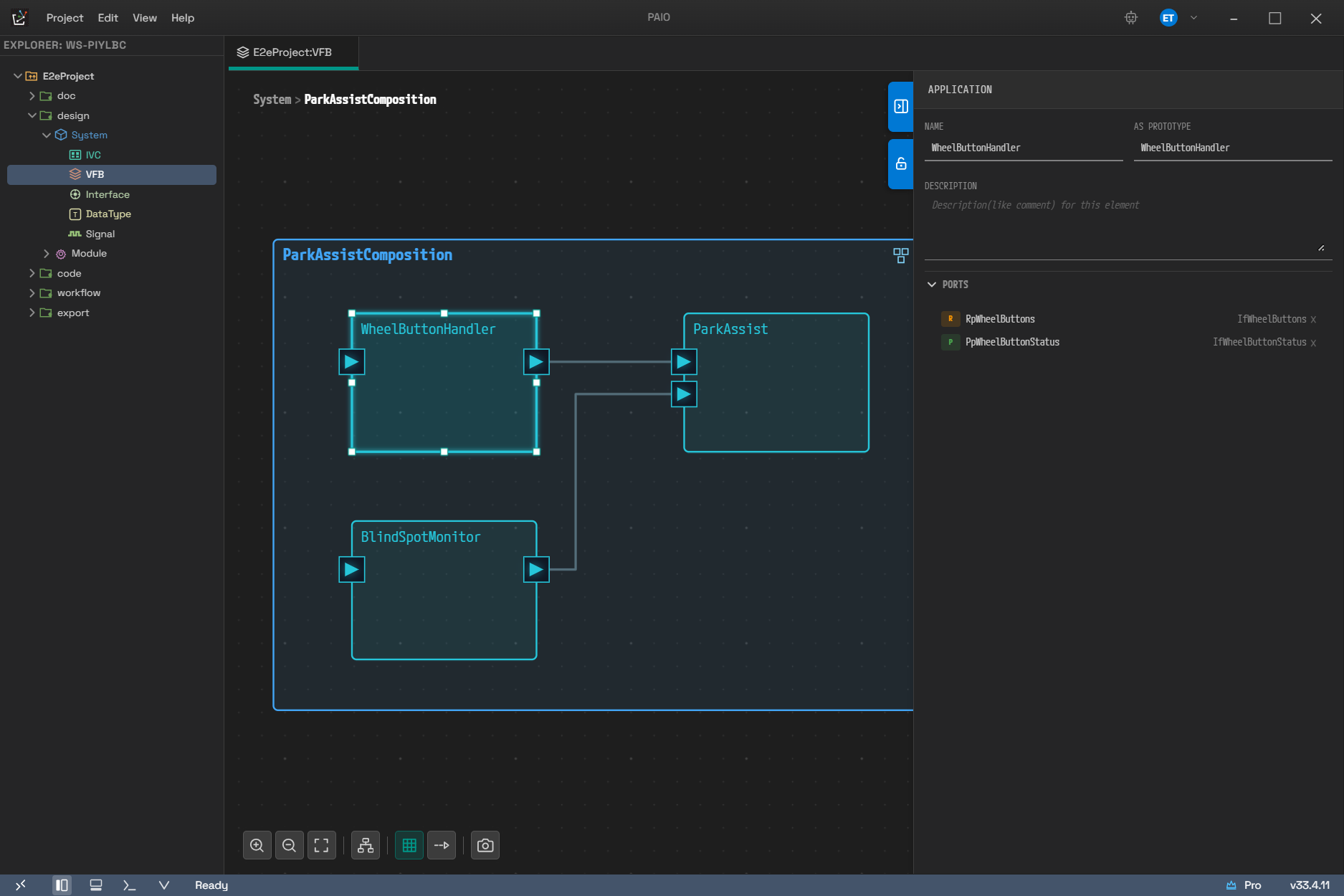
The screen with the Atomic SWC WheelButtonHandler selected. The panel title changes to APPLICATION, and Ports shows RpWheelButtons with an R badge and PpWheelButtonStatus with a P badge, each next to its PortInterface name.
Port Node
Selecting a port shows the following fields.
| Field/Section | Contents |
|---|---|
| Name | The port SHORT-NAME |
| Port Interface | A searchable reference drop-down plus a [+] button that creates a new interface. Clearing it shows the Port-Interface is required error |
| ComSpec section | One section is attached according to the interface category, as in the table below |
| Data Mapping | Appears only for a composition boundary port that has data elements |
The ComSpec section name depends on the interface category as follows.
| Interface category | ComSpec section name |
|---|---|
| Sender-Receiver | Data Element |
| Client-Server | Operation |
| Service | Service ComSpec |
| Mode-Switch | Mode Group |
You edit the initial value (Init Value) with the shared ValueSpecEditor widget.
The candidates in the Port Interface drop-down are filtered by the parent SWC kind as follows.
| Parent SWC kind | Candidates |
|---|---|
| Adaptive Application | ServiceInterface plus the whole AP family (with the direction constraints below applied) |
| Composition | Everything except the AP family (ServiceInterface and the CP family) |
| Any other Atomic SWC | Only the three: Sender-Receiver · Client-Server · Mode-Switch |
Adaptive Application ports also get a direction constraint. The port directions you can choose per interface are the following.
| Interface | Selectable port directions |
|---|---|
| ServiceInterface | PPort · RPort (not offered on a PRPort) |
| PhmRecoveryNotification · SynchronizedTimeBaseProvider · NetworkManagement · IdsmTimestampProvider · IdsmContextProvider | PPort |
| The two Persistency interfaces (KeyValueStorage · FileStorage) | PPort · RPort · PRPort |
| The whole rest of the AP family (LogAndTrace · the four SM interfaces · PhmSupervisedEntity · SynchronizedTimeBaseConsumer · the five Crypto interfaces · the four RDS interfaces · the remaining three IDSM interfaces) | RPort |
Each item in the list carries a kind prefix, such as SenderReceiver:, Service:,
SM.StateClient:, or Crypto.KeySlot:.
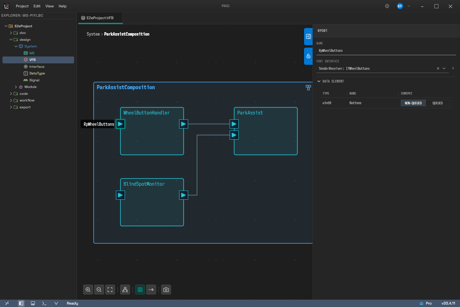
The screen with the port RpWheelButtons selected. The panel title is RPORT, and Port Interface holds SenderReceiver: IfWheelButtons with its kind prefix. The interface is Sender-Receiver, so the ComSpec section is named DATA ELEMENT and shows one row reading uint8 / Buttons / NON-QUEUED.
Connections
The Basic Info section has a single Name field.
InterfaceMapping Node
Selecting an InterfaceMapping node shows the following fields.
| Field/Section | Contents |
|---|---|
| Name | The mapping SHORT-NAME |
| Description | The description |
| Interfaces | Service Interface (read-only) plus the Mapped Port Interfaces list |
| Event Mappings | Service event → SR data element |
| Method Mappings | Service method → CS operation. Fire&Forget methods carry an F&F badge |
| Field Mappings | Service field → Notifier / Getter / Setter |
| Connected Ports | The list of ports connected to this node |
When the service interface is not resolved yet,
Connect to a ServiceInterface port to configure element-level mappings. appears in place of the
element-level mapping sections.
Selecting something in the properties panel does not change the model. Even when an empty row is already visible in a mapping table, it is only a skeleton for display; the actual value is recorded the first time you edit it.
8.8 SWC Internal Behavior Dialog
This dialog opens when you double-click an Application, Complex Device Driver, Service,
Ecu Abstraction, or Sensor Actuator node. The title is SWC Internal Behavior [<SWC name>]. The
left side is an SVG canvas and the right side is a properties panel.
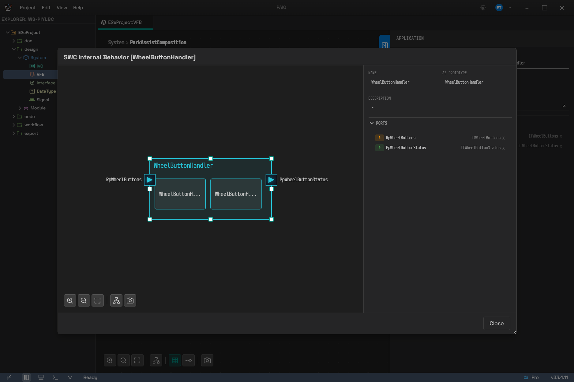
The dialog opened by double-clicking WheelButtonHandler. The canvas on the left holds the SWC body, the ports attached to both of its sides, and two Runnables inside it. The right side has the same layout as the properties panel shown earlier.
Right-Clicking the Canvas
The menu changes with what you right-click. The items per target are the following.
| Right-click target | Items |
|---|---|
| The SWC body | ADD Port ▸ PPort / RPort / PRPort, ADD RUNNABLE, ADD IRV |
| A port | DELETE |
| A Runnable | ADD RTEEvent ▸ the seven RTE events, DEL RUNNABLE |
| An RTE event icon on a Runnable | DEL EVENT |
| An IRV | DELETE IRV |
| An ITP | Add Triggered Runnable ▸ the candidate Runnable list (the item itself disappears when there is no candidate), DELETE ITP |
Selecting an element on the canvas and pressing Delete or Backspace deletes the selected port,
Runnable, IRV, or ITP (it is ignored while an input field has focus).
Runnable Properties
Selecting a Runnable sets the title of the right panel to Runnable and shows the basic fields in a
2×2 grid. Each field means the following.
| Field | Description |
|---|---|
| NAME | The AUTOSAR SHORT-NAME. A duplicate within the same SWC shows the A runnable with this name already exists error and is not committed |
| SYMBOL | The C function name in the generated code (C-IDENTIFIER) |
| CAN BE INVOKED | TRUE / FALSE |
| MIN START INTERVAL | The minimum start interval (0 or greater) |
Below them are two accordion sections, Access Points and RTE Events. Clicking the +
button in either section header opens a kind-selection menu.
The + menu of RTE Events offers seven events. The ADD RTEEvent submenu you get by
right-clicking a Runnable node offers the same seven.
- TimingEvent
- BackgroundEvent
- DataReceivedEvent
- OperationInvokedEvent
- SwcModeSwitchEvent
- InitEvent
- InternalTriggeredEvent
The + menu of Access Points offers ten items: the nine access points plus
InternalTriggeringPoint.
- DataSendPoint
- DataReceivedPoint
- SyncServerCallPoint
- DataWriteAccess
- DataReadAccess
- WrittenLocalVariable
- ReadLocalVariable
- ModeSwitchPoint
- ModeAccessPoint
- InternalTriggeringPoint
InternalTriggeringPoint sits in the same + menu as the access point list, but it is stored as
a separate element owned by the Runnable rather than as a VARIABLE-ACCESS. Create an
InternalTriggeredEvent from the RTE event menu first, then choose which ITP to bind it to in the
INTERNAL TRIGGERING POINT field of the detail panel.
Selecting an access point or an RTE event shows the detail fields for that kind below. Examples are LOCAL VARIABLE, MODE GROUP, TIMEOUT, PERIOD, OFFSET, R-PORT / P-PORT, DATA ELEMENT, OPERATION, and TARGET MODE.
Holding Shift and dragging from a port onto a Runnable shows a menu that contains only the items
matching the direction and the interface category of that port. For example, a P-Port with
Sender-Receiver suggests DataSendPoint and DataWriteAccess, an R-Port with Client-Server suggests
SyncServerCallPoint, and a P-Port with Client-Server suggests OperationInvokedEvent. Dragging an IRV
onto a Runnable the same way shows a menu offering READ or WRITE, and the local variable
access point that matches your choice is created.
8.9 AA Internal Behavior Dialog (Adaptive Application)
This dialog opens when you double-click an Adaptive Application node. The title is
AA Internal Behavior [<node name>]. The panel on the right has two tabs.
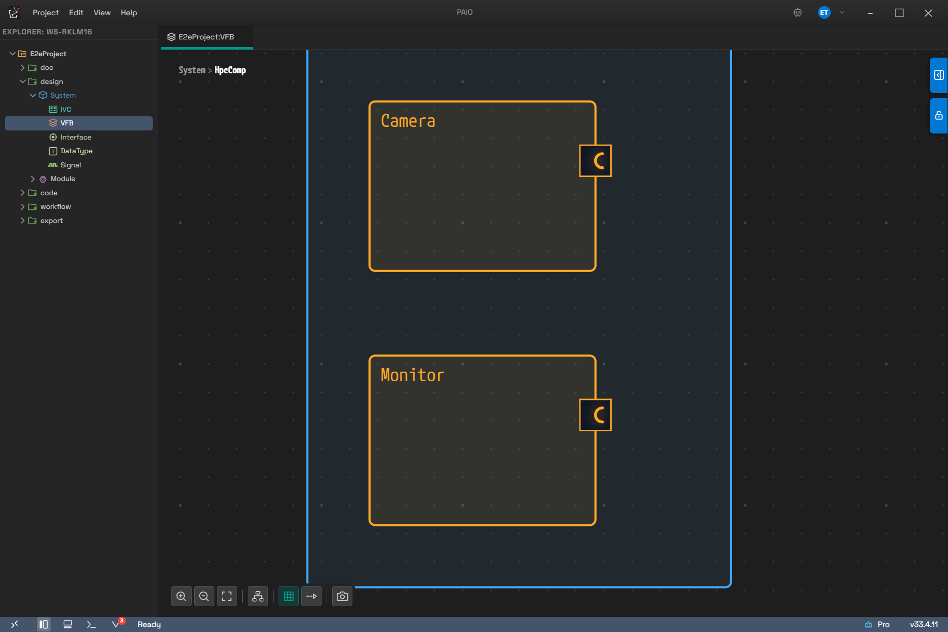
The target that opens this dialog. An Adaptive Application node is drawn in a different color from other SWCs, and the half-circle ports on its right edge are AP family interfaces.
| Tab | Contents |
|---|---|
| PROPERTIES | Executable information — NAME, ROOT SWC PROTOTYPE, the category (APPLICATION / PLATFORM), the build type (DEBUG / RELEASE), VERSION, and MINIMUM TIMER GRANULARITY. Selecting a mapping box shows the properties of that box instead |
| EXECUTION | The Process list. Expanding a process row shows NAME and the four subsections below |
The subsections of a process row on the EXECUTION tab are the following.
| Subsection | Items |
|---|---|
| STARTUP CONFIG | ENTER TIMEOUT, EXIT TIMEOUT, CPU USAGE, MEM USAGE, SCHEDULING POLICY, SCHEDULING PRIORITY, EXECUTION ERROR, TERMINATION BEHAVIOR |
| FUNCTION GROUP STATE | A list of function group : state rows. Add one with the + in the header and remove one with the × at the end of the row. No function group states defined when it is empty |
| EXECUTION DEPENDENCY | A list of process : state rows. No execution dependencies defined when it is empty |
| LOG CONFIG | APPLICATION ID, APPLICATION DESCRIPTION, DEFAULT LOG LEVEL, LOG MODE, and CONTEXT ID / CONTEXT DESCRIPTION per DLT context |
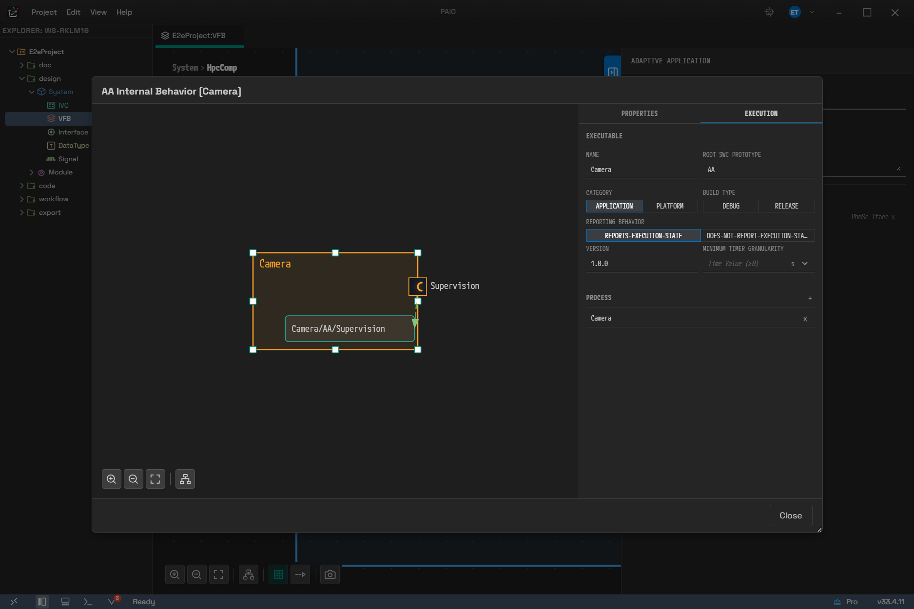
The dialog opened by double-clicking Camera, with the EXECUTION tab selected. EXECUTABLE at the top holds segments such as the category and the build type, and PROCESS below it holds the process list. The green box on the left canvas is a PHM supervision target.
Right-Clicking the Canvas (the AA Body)
Right-clicking the AA body shows the following menu.
| Item | Behavior |
|---|---|
| ADD Port ▸ PPort / RPort / PRPort | Adds a port |
| ADD Instance ▸ function cluster ▸ item | Adds an AP mapping box |
The ADD Instance menu is grouped by AUTOSAR AP function cluster. There are 10 clusters and 22 items in total. Items whose condition is not met drop out of the menu, and ara::crypto disappears as a cluster when all four of its items drop out. The items and the display conditions per cluster are the following.
| Cluster | Item | Display condition |
|---|---|---|
| ara::com | Service Instance | Always |
| ara::log | DLT Sink | Always |
| ara::sm | Function Group | Always |
| ara::phm | Supervised Entity | When there is an HPC/Machine above it |
| ara::phm | Recovery Notification | Always |
| ara::nm | Network Handle | The whole cluster appears only when the nm module of the Machine has at least one NM network handle |
| ara::tsync | Time Base | The whole cluster appears only when the Machine has at least one TimeBaseResource |
| ara::crypto | Crypto Key Slot / Crypto Certificate / Crypto Certificate Group / Crypto Provider | Per item, when the crypto module of the Machine has the matching element (Key Slot when a Provider with key slots exists) |
| ara::idsm | Timestamp Provider / Context Provider / Reporting Mode Provider / Qualified Event Receiver / Security Event | The whole cluster appears only when the Machine has an idsm module |
| ara::per | Key Value Storage / File Storage | Always |
| ara::rds | Raw Data Stream Client / Raw Data Stream Server / Raw Data Stream IEEE1722 Consumer / Raw Data Stream IEEE1722 Producer | Always |
ara::idsm ▸ Timestamp Provider may be in the menu, but if the IDSM module of the Machine already has an Ids Time Base assigned, the addition is rejected and a notice appears (the two cannot be used at the same time).
Right-clicking a mapping box shows DEL Instance, and right-clicking a port shows DELETE.
Shift + drag from a port draws a connection to a mapping box.
If a cluster with a condition is not visible, create the element of that module in the Machine Configuration dialog (8.10) first. For example, if ara::tsync ▸ Time Base is missing, add one time base under MODULE tab ▸ TS ▸ TIME BASES and open the menu again.
8.10 Machine Configuration Dialog (Adaptive)
This dialog opens when you click the blue HPC icon on a composition node mapped to an HPC. It has four tabs.
| Tab | Contents |
|---|---|
| MACHINE | OS (the SHORT-NAME of the OS module instance), TRUSTED PLATFORM (STRICT / MONITOR / NO SUPPORT), DESCRIPTION, and the PROCESSOR name with a two-column core table of Core / Core ID |
| FUNCTION GROUP | The Function Groups list on the left (+ / − / ⚡), CONFIGURATION in the middle (Name · Description · MODE DECLARATION), and the state machine diagram on the right |
| PROCESSES | Shows the Adaptive Application processes of this composition in three panes: the Processes list on the left, the details in the middle, and the process graph on the right (8.10.2) |
| MODULE | AP function cluster module configuration (8.10.1) |
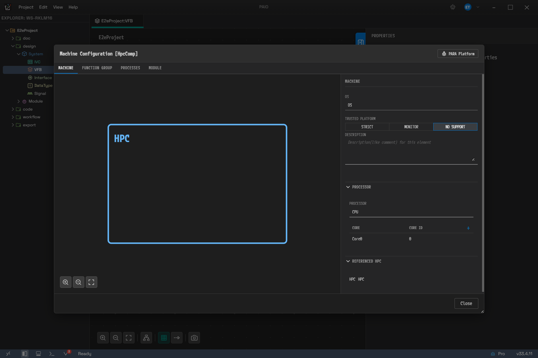
The four tabs, with the first one, MACHINE, open. TRUSTED PLATFORM is NO SUPPORT, one of its three values, and PROCESSOR holds the single CPU / Core0 (Core ID 0) entry filled in automatically as described below. The PARA Platform button at the top right is covered in 8.11.
The elements the dialog needs are filled in automatically when it opens.
- If the MachineFG function group is missing, it is created. This group cannot be deleted, and
five of its mode declarations —
Off,Startup,Shutdown,Restart, andVerify— cannot be removed. - If the ten module instances are missing, they are created with the fixed names
LOG,CM,SM,NM,PHM,TIME_SYNC,CRYPTO,PERSISTENCY,IDSM, andUCM. The MODULE tab therefore always shows all ten. - If processor information is missing, it is filled in with a single
CPU/Core0(Core ID 0).
Adding a new Function Group creates a group whose initial mode is Off. MachineFG cannot be
renamed. The ⚡ button on the FUNCTION GROUP tab re-aligns the StateClient interfaces and the
R-Ports of the SM SWC with the current function group list. If no HPC is connected yet, a notice
asks you to save once first. On a successful run the result appears in a notice dialog. When nothing
changed it reads
All StateClientInterfaces and SM SWC R-Ports are already in sync with the configured Function Groups.,
and when something changed it reads
Synchronized StateClientInterface and SM SWC R-Ports: 2 created, 1 removed.
Deleting a function group with − opens a Delete Function Group confirmation dialog first. The
body tells you that the StateClient interfaces generated from that group are removed from the
Interface editor as well. MachineFG cannot be deleted with this button either.
If the PROCESSES tab has no process,
No Adaptive Application processes found in this Composition appears; if no process is selected,
Select a process appears. If the MACHINE tab has no core,
No processor cores defined in MACHINE tab appears in place of CORE AFFINITY.
This dialog has many features. The ten module instances are created automatically when the dialog opens, so at first you can edit only the cluster you need now and leave the rest alone.
8.10.1 The Ten Modules on the MODULE Tab
Selecting a module in the list on the left shows an editing view in the middle and an overview canvas on the right. Each module is made up as follows.
| Badge | Module | Middle editing view | Right overview |
|---|---|---|---|
| LOG | Log and Trace | A DLT ECU section plus the DLT APPLICATION table (Process / DLT Application ID / Log Mode / Default Log Level) | A DLT hierarchy viewer (DltEcu → DltApplication → DltContext) |
| CM | Communication Management | The ACCESS CONTROL + GRANTS accordions | None |
| SM | State Management | Three subtabs: NOTIFICATIONS / REQUESTS / ACTION ITEMS | A state machine and wiring diagram |
| NM | Network Management | The NETWORK HANDLES subtab (Name / VLANs / Partial Networks per handle) | The NM state machine of the selected handle |
| PHM | Platform Health Management | Two subtabs: CHECK POINTS / GLOBAL SUPERVISIONS | A supervision checkpoint transition diagram |
| TS | Time Synchronization | The TIME BASES subtab (choose Provider or Consumer, then create) | A GlobalTime hub-and-spoke diagram |
| CRY | Cryptography | Three subtabs: PROVIDERS / CERTIFICATES / CERT GROUPS | None |
| PER | Persistency | Two subtabs: KEY VALUE STORAGES / FILE STORAGES | None |
| IDS | Intrusion Detection | The Network Endpoint section (with Remote Configs beneath it), Ids Time Base, and Reportable Security Events | None |
| UCM | Update and Configuration Management | Two subtabs: VUCM (UCM Master) / UCM (UCM Subordinate) | None |
For a module with no overview, No overview for this module appears on the right.
On the ACTION ITEMS subtab of SM you can drag item cards to change their order within the list. The new order is recorded in the model as it is and carried into the export as it is, and a single undo reverts the reordering.
Each storage row of PER has a ⚡ Derive PersistencyInterface action. Running it builds a
Persistency interface from the storage contents and adds it to the INTERFACE model of the Interface
editor (see 09. Interface Editor).
UCM has no SHORT-NAME field, because the export uses fixed standard names.
8.10.2 The PROCESSES Tab
The Processes list on the left names every process of the Adaptive Applications in this
composition as <AA name>/<process name>. Selecting a process fills the detail panel in the middle
in the following order.
| Area | Contents |
|---|---|
| CORE AFFINITY | Chooses which core this process is pinned to. It is the only editable value in the body of the detail panel |
| Adaptive Application information | Information about the AA node that owns the process (read-only) |
| STARTUP CONFIG | The startup configuration (read-only) |
| FUNCTION GROUP STATE | A list of function group : state. No FG states configured when it is empty |
| EXECUTION DEPENDENCY | The execution dependency list. No execution dependencies when it is empty |
The panel on the right draws the process graph. It places each process as a box and joins the function group states and the execution dependencies with lines.
Assigning a Function Cluster (Mark as SM / Mark as PHM)
There are two buttons at the right of the detail panel header. They assign the AP function cluster
affiliation (functionClusterAffiliation) of a process, and within one Machine each affiliation can
have only one process.
| Button | Value assigned | Once assigned |
|---|---|---|
| Mark as SM / Unmark as SM | State Management | A STATE_MANAGEMENT badge appears in the header |
| Mark as PHM / Unmark as PHM | Platform Health Management | A PLATFORM_HEALTH_MANAGEMENT badge appears in the header |
Clicking the × inside the badge also clears the assignment.
Assigning SM also creates the wiring. Mark as SM does not only record the affiliation value; it also creates a StateClient R-Port and a FunctionGroupPortMapping on the SM SWC for every current function group. Clearing it removes that wiring again. That is why clearing and reassigning come with a confirmation dialog. The dialogs per situation are the following.
| Situation | Confirmation dialog title | Confirm button |
|---|---|---|
| Clearing the SM assignment | Unmark as State Management | Unmark |
| Mark as SM while another process is already SM | Reassign State Management | Reassign |
| Mark as PHM while another process is already PHM | Reassign Platform Health Management | Reassign |
| Mark as PHM on a process assigned as SM | Process is State Management | Cannot proceed. Only a notice asking you to clear SM first appears |
Assigning PHM creates no wiring. It records only the affiliation value, so both assigning and clearing take effect immediately without confirmation.
Clearing an assignment removes the R-Port and the FunctionGroupPortMapping of the SM SWC and nothing more. The StateClient interface itself, created in the Interface editor, is left in place.
Assigning, clearing, and reassigning are each recorded as one entry in the VFB edit history.
Even when the wiring is created or removed once per function group, the entry is single, so one undo
reverts all of it. Pressing Ctrl+Z inside the dialog consumes the edit history of the dialog
itself first (see 18.3), so to revert only an assignment or its
clearing, close the dialog and then press Ctrl+Z.
Some items behave differently from what they show. The body of the SM clearing confirmation dialog ends with
This action cannot be undone., but in practice you can revert it with undo, as described above.
8.11 PARA Base Configuration
This feature injects the PopcornSAR AUTOSAR Adaptive Platform base configuration into the project. There are two ways to run it.
- Click the PARA Platform button in the header of the Machine Configuration dialog. If the dialog has unsaved edits, it asks whether to save them first. Click Import in the confirmation dialog and the dialog closes, then the injection starts (the injection is a project-level undo unit, so it must run outside the internal edit transaction of the dialog).
- Run PARA: Import Platform from the command palette.
The command palette path is handled by the active VFB editor, and it proceeds directly only when
exactly one composition is mapped to an HPC. Otherwise the toast
Select the target machine via the PARA Platform button in the Machine Configuration dialog.
appears. If no VFB editor is open,
Open a VFB editor with an HPC-mapped composition, or use the PARA Platform button in the Machine Configuration dialog. appears.
The confirmation dialog is titled Import PARA Platform with the subtitle
PopcornSAR AUTOSAR Adaptive Platform, and its buttons are Cancel / Import. The figures
shown in the dialog are counted from the bundle each time. The values per item are the following.
| Item | Value in the bundle |
|---|---|
| Applications | 11 (CM, CSM, DM, EM, IDSM, NM, PHM, SM, TBM, UCM, VUCM) |
| Service Interfaces | 8 (+1 SM) — eight service interfaces plus one SM interface, StateClient_MachineFG |
| Error Domains | 4 (Com / Sm / Ucm / Vucm) |
| Data Types | 62 |
| Connectors | 5 (the connectors of the PARA composition. This composition has 11 prototypes and three provided ports) |
| Machine | The MachineFG function group plus seven module instances (LOG, CM, SM, NM, PHM, TIME_SYNC, CRYPTO) |
The confirmation dialog also shows the following two lines of notice.
Network binding (SOME/IP, DDS, IPC) is not included. Configure it in Deployment after adding.Existing items with different content will ask for per-item confirmation.
The injection uses the same merge pipeline as an ARXML import. A conflict therefore opens the conflict resolution dialog, and the whole operation is recorded as a single undo unit. On success the Machine Configuration dialog of the same machine reopens and shows the merged result of MachineFG and the modules.
The machine file in the bundle is not added as a separate machine. Only the function groups and
module instances inside it are merged into the machine you selected, and identity fields such as the
machine name, the processor, and the OS are left untouched. The HPC/... references in the bundle
are rebound to the target machine name at injection time. The IVC and SIGNAL models are not in the
bundle, so they stay as they are, and the SYSTEM model changes only as far as registering the target
machine as an HPC and recording the SWC-ECU mapping.
8.12 ECU Configuration Dialog (Classic)
This dialog opens when you click the green ECU icon on a composition node mapped to an ECU. It has two tabs.
| Tab | Contents |
|---|---|
| ECU | Shows the ECU information read from IVC as read-only — the CONNECTORS, CONTROLLERS, SERVICE INSTANCES, and APPLICATION ENDPOINTS tables |
| TASK | Edits OS tasks and Runnable mappings |
The OS TASKS list on the left of the TASK tab has the + (Add Task), − (Delete Task), and
⚡ (Auto-Generate) buttons. + creates a task named OsTask_<number> with priority 1, schedule
FULL, and activation 1. No tasks defined appears when there is no task, and
Select a task from the list when none is selected.
⚡ (Auto-Generate) groups TimingEvents by cycle time, creates one task (OsTask_<cycle>ms) and
one alarm (OsAlarm_<cycle>ms) per cycle time, and assigns the matching events to that task. If no
counter exists, it creates OsCounter as well. Take care here: it replaces the existing task and
alarm lists wholesale. Events other than TimingEvents are left unassigned.
The TASK CONFIGURATION panel in the middle is split into two parts.
| Part | Contents |
|---|---|
| The OS TASK section | The task name, Task Schedule (FULL / NON), Task Priority, the activation count, the Autostart switch with the Os App Mode reference beside it, and OS EVENT (an event reference plus the hexadecimal EVENT MASK field) |
| The OS ALARM accordion | The + in the header links an alarm or creates a new one, and × breaks the link. Expanding it shows the alarm name, OS COUNTER, and AUTOSTART (Autostart Type: ABSOLUTE / RELATIVE) |
The RTE EVENT TO TASK MAPPING panel on the right assigns RTE events to the task. When no event
is mapped, No events mapped to this task appears; when every event is mapped,
All events are mapped appears. If this composition has no Atomic SWC instance,
No Atomic SWC instances found in this ECU composition. appears.
You can drag an already mapped row to change its order. Grab a row and drag it up or down: an insertion line appears, and releasing the row moves it there. This order is the execution order within the task, and the rows are renumbered from 0 at the top and recorded in the model. A single undo reverts the reordering. Rows for events that are not mapped yet cannot be dragged.
The contents of the TASK tab are synchronized both ways with the Os and Rte module
configurations. Tasks you create here therefore also appear in 12. ECUC.
8.13 Saving, Undo, and External Changes
- Saving with
Ctrl+Swrites the files of 8.1 in one go and deletes the SWC definition and Machine configuration files that a rename made obsolete. - Undo and redo use one timeline shared by every editor of a project. Changes to the position · size · port positions · boundary ports of a VFB node and to connection routes are undoable as well. Only panning and zooming are excluded from undo, because they are view state.
- If the VFB file on disk changes externally while you have pending edits, PAIO does not reload
it and keeps your edits. A warning toast then appears:
VFB files changed on disk. Keeping your unsaved edits - save to overwrite the external change.Saving overwrites the external change with your edits. The same rule applies when a detail dialog is open and holds unsaved edits.
8.14 Integration with Other Editors
- The mapping between a composition and an ECU/HPC is synchronized in real time with the IVC editor and the System editor. Create ECU & Map / Create HPC & Map create the node in IVC directly.
- The interface you assign to a port refers to the definition in 09. Interface Editor. When you rename an interface, an open VFB updates immediately, and closed SWC definition files are updated by reference rewriting.
- DERIVE SR/CS INTERFACE on a port creates the SR/CS interfaces and the InterfaceMapping in one step. The change spans the Interface model and the VFB model and is recorded as a single undo unit.
- An InterfaceMapping is stored in the VFB model, so the Mapping tab of the Interface editor edits the same data. A change on either side is reflected on the other (see 09. Interface Editor, 9.3.7).
- Renaming an SWC also updates the prototype references of the composition, the connector references, and the SYSTEM mappings, and the file name changes with it on save.
- ARXML import and export are described in 13. Import and Export.
- The full shortcut list is in 19. Keyboard Shortcuts.