Signal Editor
What This Chapter Covers
This chapter describes the Signal editor, which edits the communication data dictionary — CAN and LIN frames, the six PDU kinds, I-Signals, and signal groups. It covers the screen layout, the editable fields for each item type, the bit layout preview, and how to edit initial values. The DBC and ARXML import and export procedures themselves belong to 13. Import and Export; this chapter goes only as far as explaining where their results appear on screen.
The intended reader writes a bus communication matrix, or reviews and edits an imported one. A project must be open before you start.
Double-click the design ▸ System ▸ Signal node in the Explorer to open the editor in a tab.
It saves to a single Signal model. Terms that are easy to confuse, such as a signal's two names
(I-Signal and System Signal),
are collected in 21. Glossary.
7.1 Screen Layout
The editor consists of a protocol tab bar across the top and three vertical panels below it.
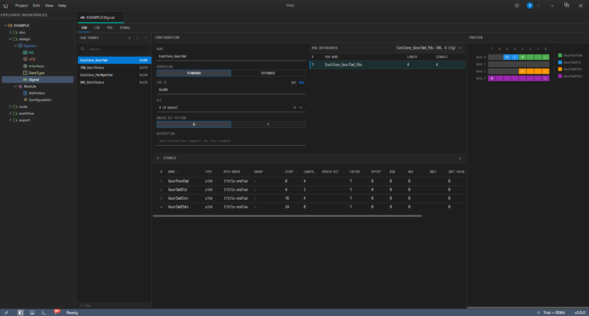
The Signal editor — the protocol tab bar and the list, Configuration, and Preview panels
Each panel holds the following content and resizes as described.
| Panel | Content | Width |
|---|---|---|
| List (left) | The items on the current tab | Drag to resize |
| Configuration (center) | The property form for the selected item, plus the Signals grid | Takes the remaining width |
| Preview (right) | The bit layout, or the signal group tree | Drag to resize |
The Signals grid appears only on the frame tabs, and on the PDU tab when you select an
I-Signal I-PDU or an NM-PDU. For the other PDU kinds and on the SIGNAL tab, the Configuration
form uses the full panel height. The LIN event-triggered and sporadic frames are on a frame tab, but
they show a read-only list instead of the grid (7.7.2).
7.2 Protocol Tabs
The tab bar has four tabs.
| Tab | What you edit | List panel title |
|---|---|---|
| CAN | CAN and CAN FD frames | CAN Frames |
| LIN | LIN frames | LIN Frames |
| PDU | All six PDU kinds in one list | PDUs |
| SIGNAL | The signal (I-SIGNAL) dictionary | Signals |
There is no FlexRay tab and no Ethernet tab. You cannot edit FlexRay or Ethernet frames in this editor. Imported data is preserved in the file and is included in the export.
The NM-PDU has no tab of its own. You edit it on the combined PDU tab as one of the six PDU kinds.
7.3 The Left List Panel
Header Buttons
The list panel header has three buttons.
| Button | Tooltip | Action |
|---|---|---|
| + | Add | Adds an item of the kind the current tab holds. On the PDU tab, a kind-selection menu opens |
| − | Remove | Deletes the selected item. Disabled when nothing is selected |
| ⋯ | Sort & Filter | Opens the filter and sort popover |
Search and the Status Bar
- The search field uses the placeholder
Search.... It filters the list by matching what you type against item names as a case-insensitive substring. - Press
Escin the search field to clear the search term and restore the full list. - The status bar under the list reports the item count. Normally it shows only the total, as
N items. It switches toM / N itemsonly when a search term has reduced the result. A reduction from the PDU kind filter (7.4) does not use this fraction form, so with only a filter applied the status bar number can be larger than the number of rows you see. - Give the list focus and press the arrow keys to move between items; the selection follows.
Empty State and No Search Results
When the list is empty or the search returns nothing, the following text appears.
| Situation | Text shown |
|---|---|
| The frame tab has no items at all | Add a frame |
| The PDU tab has no items at all | Add a PDU |
| The SIGNAL tab has no items at all | Add a signal |
| Items exist, but the search or filter matches none | No results found |
Badges on List Items
Each list item carries a badge that depends on the tab.
| Tab | Badge |
|---|---|
| CAN | The frame ID in hexadecimal (0x1A0) |
| LIN | The frame ID in hexadecimal (0x3F) |
| PDU | A kind tag on the left, the length on the right (8B) |
| SIGNAL | The bit length (8bit) |
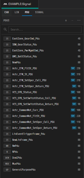
PDU tab list — kind tags, origin badges, and length badges
The PDU kind tags are IS (I-Signal I-PDU), NM (NM-PDU), N (N-PDU), DCM (DCM-I-PDU),
MUX (Multiplexed I-PDU), and GP (General Purpose PDU). Hover over a tag to see the full name in a
tooltip.
Items the tool generated automatically carry an additional origin badge. SOC marks an item derived
from a service deployment (CP-SOA), and COM marks an SR-based COM-derived signal. The badge only
reports origin; it does not lock the item for editing. You can rename, change, and delete a derived
item like any other.
7.4 The More (⋯) Menu — Filter and Sort
Click the ⋯ button to open the popover. Clicking a check box inside it does not close the popover, so you
can work through several items in a row. Press Esc to close the popover alone.
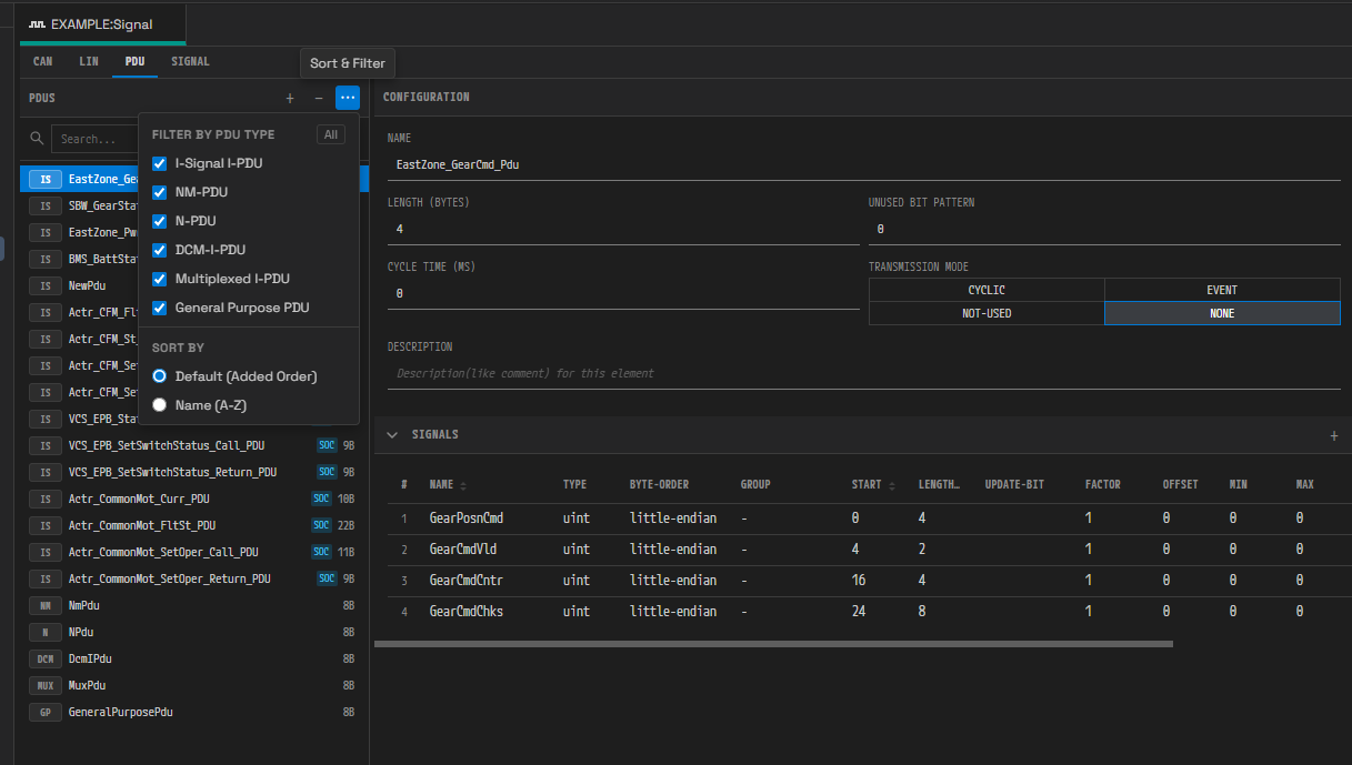
The filter and sort popover in the ⋯ menu (the PDU tab has no ID sort)
The popover has the following sections.
| Section | Shown when | Items |
|---|---|---|
Filter by PDU type | On the PDU tab only | A check box for each of the six PDU kinds, plus an All button on the right (tooltip Select All / Deselect All) |
Sort by | On every tab | Default (Added Order) / Name (A-Z) / ID |
The ID sort option appears only on the frame tabs (CAN and LIN). The PDU tab and the SIGNAL tab have no
IDs, so they offer the other two options only. Sorting changes the display order on screen; the order
stored in the file stays as it was.
7.5 The Six PDU Kinds
Click + on the PDU tab to open a two-level menu. Hover over an entry on the left to expand its submenu on the right, then click a submenu entry to create a PDU of that kind.
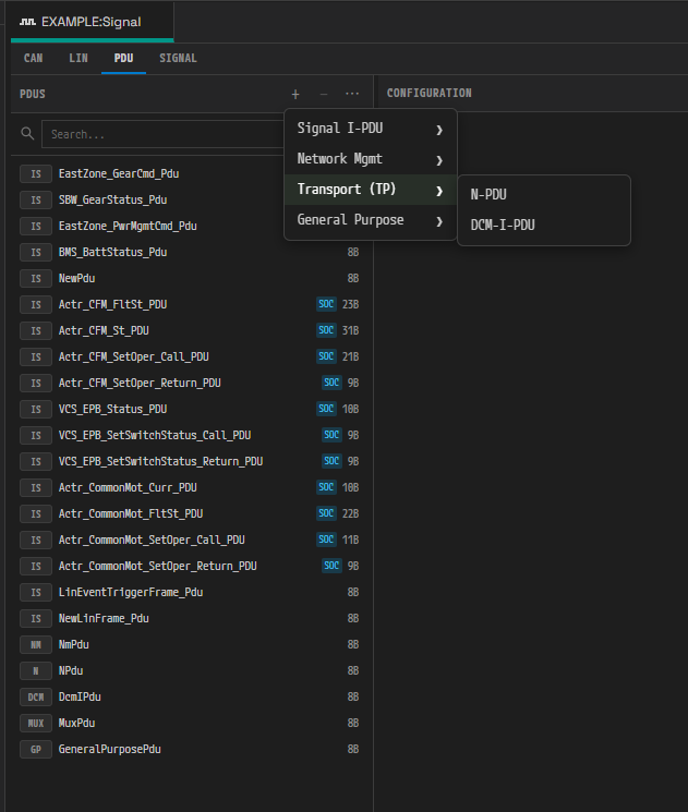
Adding a PDU — the two-level menu with the Transport (TP) submenu expanded
The menu structure and the defaults for each kind are as follows.
| Group | Entry | List tag | Defaults for a new item |
|---|---|---|---|
Signal I-PDU | I-Signal I-PDU | IS | Name NewPdu, length 8 bytes, Unused Bit Pattern 0 |
Signal I-PDU | Multiplexed I-PDU | MUX | Name NewMuxPdu, length 8 bytes, Trigger Mode NONE, one empty Dynamic Part |
Network Mgmt | NM-PDU | NM | Name NewNmPdu, length 8 bytes, NM Vote Information false |
Transport (TP) | N-PDU | N | Name NewNPdu, length 8 bytes |
Transport (TP) | DCM-I-PDU | DCM | Name NewDcmIPdu, length 8 bytes, Diag PDU Type DIAG-REQUEST |
General Purpose | General Purpose PDU | GP | Name NewGeneralPurposePdu, length 8 bytes, Category SD |
If the name already exists, the editor appends an underscore and a number to make it unique, giving
NewPdu_1, NewPdu_2, and so on. Items of different kinds stay distinct even when they share a name,
and the list compares both name and kind when it highlights the selection.
7.6 Adding and Deleting Items
Adding a Frame (CAN / LIN Tabs)
- Select the tab and click +. The editor creates the new frame together with a PDU dedicated to that frame.
- The new frame is selected automatically, and its property form appears in the Configuration panel.
The defaults per tab are as follows.
| Tab | Frame defaults | PDU created alongside |
|---|---|---|
| CAN | Name NewFrame, DLC 8, Addressing standard, ID is the first free value from 0x100 | NewFrame_Pdu, length 8 bytes |
| LIN | Name NewLinFrame, length 8, Checksum enhanced, ID is the first free value from 0x00 | NewLinFrame_Pdu, length 8 bytes |
Adding a Signal
There are two entry points for creating a signal.
- The + on the SIGNAL tab — adds a signal to the dictionary only. Its name is
NewSignal, with bit length 8, typeuint, Factor 1, Offset 0, Min 0, Max 255, and initial value 0. It is not mapped to any PDU. - The + in the Signals grid header (tooltip
Add Signal) — creates the signal and its mapping to the currently selected frame or PDU. The name takes the owner's name as a prefix, giving<ownerName>_Sig. The prefix is the frame name on a frame tab, and the name of the selected I-Signal I-PDU or NM-PDU on the PDU tab. If the frame references several PDUs, the signal is mapped to the first PDU that still has room.
When you add a signal through the grid and the PDU is too short, the PDU length grows automatically. If the enlarged PDU exceeds the CAN frame's current DLC, the frame's DLC is raised automatically too. A PDU that no frame references has no byte limit applied.
When the frame is full, the add is silently ignored. If the bits already placed fill the frame's maximum byte count (64 bytes for CAN, 8 bytes for LIN), clicking + does nothing, and no message appears. The editor checks capacity and rejects the request before it creates the signal, so that unmapped signals do not pile up in the dictionary. Rearrange the frame composition or the PDU layout first.
Deleting
The − button — and the × button at the end of a grid row — deletes immediately, with no
confirmation dialog. Press Ctrl+Z to undo.
The × at the end of a grid row does not just break the mapping: it removes the signal from the dictionary as well. There is no separate operation that detaches the mapping alone.
Deleting also cleans up references.
- Deleting a frame or a PDU removes its name from the connector frame and PDU references in the IVC model. If the IVC editor is closed, the editor edits the file on disk directly; if it is open, the IVC editor cleans up its own model. The NM-PDU is the exception: NM-PDU references live in the IVC network management configuration and this path does not touch them.
- Deleting a signal removes every reference to it from the mappings of all PDUs and NM-PDUs.
- The data mapping references in the System model are cleaned up only when you delete through the × in the Signals grid. Deleting with − on the SIGNAL tab cleans up the dictionary and the PDU mappings only, and leaves the System data mapping references in place. Because the two paths behave differently, delete a signal that has data mappings from the grid.
7.7 Configuration Panel — Editable Fields by Item Type
The panel header is always Configuration. With no item selected it shows a single line of guidance
(Select a frame / Select a PDU / Select an NM-PDU / Select an N-PDU /
Select a DCM-I-PDU / Select a General Purpose PDU / Select a Multiplexed I-PDU /
Select a signal).
The fields marked Choice in the tables below are drawn as a segmented button set, and the button
labels are all upper case (standard → STANDARD, false → FALSE). The value stored in the model
keeps the original spelling listed in the table.
7.7.1 CAN Frame
The left column holds the properties, the right column the PDU References grid (see 7.8). The properties are as follows.
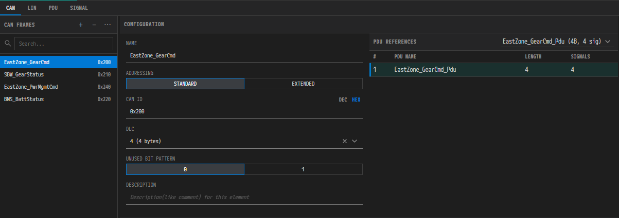
The CAN frame Configuration form and the PDU References grid
| Field | Form | Range and notes |
|---|---|---|
| Name | Text | AUTOSAR SHORT-NAME rules |
| Addressing | Choice | standard / extended |
| CAN ID | Hexadecimal input (DEC/HEX toggle) | standard allows 0x000 to 0x7FF, extended allows 0x00000000 to 0x1FFFFFFF. Change Addressing and the upper bound follows immediately |
| DLC | Searchable choice | 16 options, 0 (0 bytes) through 15 (64 bytes). Values 9 to 15 are the CAN FD extensions (12/16/20/24/32/48/64 bytes) |
| Unused Bit Pattern | Segmented | 0 / 1. This value is stored on the PDU the frame references, not on the frame |
| Description | Text |
Changing the DLC also updates the length of the PDU the frame references to that byte count. This happens only when the frame references a single PDU; on a frame that references several PDUs, only the DLC changes. The clear (×) action on the DLC field is ignored, because the value is mandatory, and the previous value is restored.
7.7.2 LIN Frame
A LIN frame has the following editable fields.
| Field | Form | Range and notes |
|---|---|---|
| Name | Text | |
| Frame Type | Choice | unconditional / event-triggered / sporadic |
| Frame ID | Hexadecimal input | 0x00 to 0x3F (the LIN 6 bits) |
| Length | Integer | 1 to 8 bytes |
| Checksum | Choice | classic / enhanced (default enhanced) |
| Unused Bit Pattern | Segmented | 0 / 1 |
| Collision Resolving Schedule | Searchable reference | Appears only when Frame Type is event-triggered. You pick from the LIN schedule tables in the IVC model; leave it empty and it reads (none) and no value is stored |
| Description | Text |
The Frame Type also changes the right column and the area below it.
| Frame Type | Right column | Area below |
|---|---|---|
unconditional | PDU References grid | Signals grid (editable) |
event-triggered / sporadic | Frame References grid | The signals of the referenced frames (read-only) |
By the LIN specification,
event-triggeredandsporadicframes carry no signals of their own; they take over the schedule slot of an unconditional frame. For these two kinds the editor therefore shows a read-only list instead of the Signals grid, and appendsread-only · from referenced framesnext to theSignalstitle.
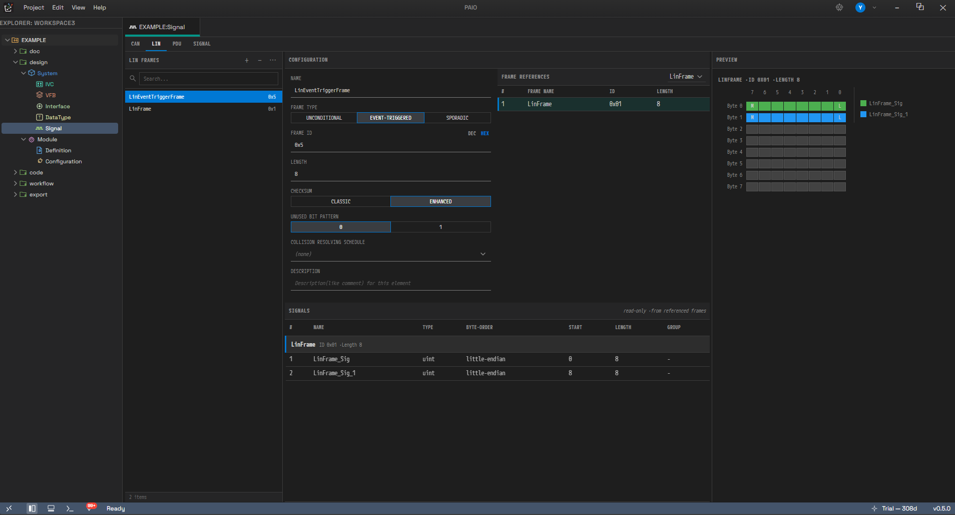
A LIN event-triggered frame — Frame References and the read-only signal list
The read-only list has the columns #, NAME, TYPE, BYTE-ORDER, START, LENGTH, and GROUP. For
each referenced frame, a separator row carrying the frame's name, ID, and length comes first, followed by
that frame's signals. The list shows the following in each situation.
| Situation | Shown |
|---|---|
| No referenced frame selected yet | Select referenced frames above to see their signals here. |
| No frame exists under the referenced name | FrameA — referenced frame not found |
| The referenced frame has no signals | (no signals) |
To edit the signals themselves, go to the unconditional frame that owns them.
7.7.3 I-Signal I-PDU
An I-Signal I-PDU has the following editable fields.
| Field | Form | Range and notes |
|---|---|---|
| Name | Text | |
| Length (bytes) | Integer | 1 or more |
| Unused Bit Pattern | Integer | 0 to 255 |
| Cycle Time (ms) | Decimal | 0 or more. The model stores milliseconds and converts to seconds on ARXML export (the value ÷ 1000) |
| Transmission Mode | Choice | cyclic / event / not-used / none |
| Description | Text |
The Signals grid and the Preview bit layout appear below the form.
7.7.4 NM-PDU
An NM-PDU has the following editable fields.
| Field | Form | Range and notes |
|---|---|---|
| Name | Text | |
| Length (bytes) | Integer | |
| Unused Bit Pattern | Integer | 0 to 255 |
| NM Vote Information | Choice | false / true |
| NM Data Information | Choice | false / true |
| Description | Text |
An NM-PDU can also carry UserData signals, so it offers the same Signals grid and bit layout Preview as an I-Signal I-PDU.
7.7.5 N-PDU · DCM-I-PDU · General Purpose PDU
These three kinds hold no signal mappings, so no Signals grid appears, and the Preview area shows a single line of guidance instead of a bit layout. The editable fields and the guidance text per kind are as follows.
| Kind | Editable fields | Preview text |
|---|---|---|
| N-PDU | Name, Length (bytes), Description | N-PDU has no signal bit-layout preview. |
| DCM-I-PDU | Name, Length (bytes), Diag PDU Type (DIAG-REQUEST / DIAG-RESPONSE), Description | DCM-I-PDU has no signal bit-layout preview. |
| General Purpose PDU | Name, Length (bytes), Category (a free-form keyword, SD on a new item), Description | PDU has no signal bit-layout preview. |
The General Purpose PDU is the only one whose guidance text reads PDU rather than the kind name.
7.7.6 Multiplexed I-PDU
The scalar properties are as follows.
| Field | Form | Range and notes |
|---|---|---|
| Name | Text | |
| Length (bytes) | Integer | |
| Unused Bit Pattern | Integer | 0 to 255 |
| Has Dynamic Length | Choice | false / true |
| Selector Field Byte Order | Choice | MOST-SIGNIFICANT-BYTE-FIRST / MOST-SIGNIFICANT-BYTE-LAST / OPAQUE |
| Selector Field Length (bits) | Integer | 1 to 16 |
| Selector Field Start Position | Integer | 0 or more |
| Trigger Mode | Choice | DYNAMIC-PART-TRIGGER / STATIC-PART-TRIGGER / STATIC-OR-DYNAMIC-PART-TRIGGER / NONE |
| Description | Text |
Two nested editing areas follow below.
| Area | Controls | When empty |
|---|---|---|
Dynamic Parts | The + in the header (tooltip Add Dynamic Part) adds a part, and each part has a − (tooltip Remove Part). Inside a part are the Segments (+ Segment) and Alternatives (+ Alternative) subtables | No dynamic parts |
Static Parts | The + in the header (tooltip Add Static Part) adds a part. Each part has an I-PDU Ref and a Segments subtable | No static parts |
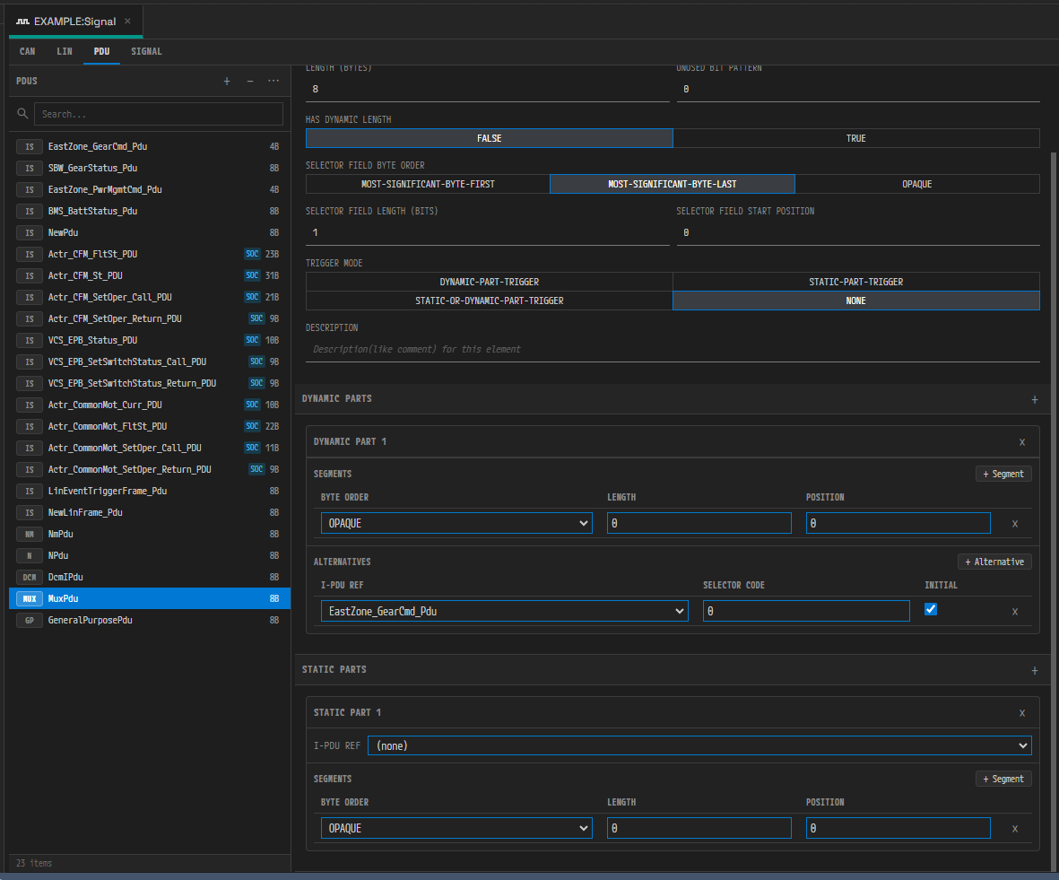
The Dynamic Parts and Static Parts nested editing areas of a Multiplexed I-PDU
Parts are numbered from 1, as in Dynamic Part 1 and Static Part 1. The Segments subtable has the
columns Byte Order, Length, and Position, plus a row-delete cell.
A Multiplexed I-PDU holds no signal mappings of its own either, so it has no Signals grid, and the
Preview area shows Multiplexed I-PDU has no signal bit-layout preview.
7.7.7 Signal (SIGNAL Tab)
A signal has the following editable fields.
| Field | Form | Range and notes |
|---|---|---|
| Name | Text | |
| Bit Length | Integer | 1 to 64 |
| Type | Choice | uint / sint / float / array / struct |
| Unit | Text | |
| Factor | Decimal | |
| Offset | Decimal | |
| Min | Decimal | |
| Max | Decimal | |
| Signal Groups | Read-only | Lists the names of the groups the signal belongs to, joined by , . If it belongs to no group, - appears |
| Init Value | Value editor | See 7.11 |
| Description | Text |
The Signal Groups field is display only. To change group membership, edit the
GROUPcolumn in the Signals grid (see 7.9).
If the signal has Text Table (enumeration) entries, a section titled like Text Table (3 entries) is
added below the form, and the entries are listed in the form Enumerator = Value. This section is
read-only (see 7.12).
Type offers five options, whereas the TYPE column in the Signals grid offers only three: uint,
sint, and float. You can set array and struct in this detail form only.
7.8 The PDU References and Frame References Grids
Select a frame and a reference grid appears in the right column of Configuration. Assign a reference as follows.
- Click the trigger next to the title. The candidate list opens as a check box dropdown. PDU candidates
show their length and signal count as well, as in
DoorPdu (8B, 3 sig). - Check the items you need. They are applied together when the dropdown closes.
- The applied items appear in the table below.
- With two or more items, a drag handle appears at the left of each row, and you can drag a row to reorder it.
The two grids are structured as follows.
| Grid | Trigger text | Table columns | Minimum count and empty state |
|---|---|---|---|
PDU References (default) | Select PDUs... | #, PDU Name, Length, Signals | At least one is mandatory — clearing them all is not applied. The empty state reads No PDU assigned |
Frame References (LIN event-triggered / sporadic) | Select Frames... | #, Frame Name, ID, Length | Zero is allowed. The empty state reads No frame references. The candidates are the unconditional LIN frames in the same cluster, excluding the frame itself |
The PDU References grid reports validation messages directly below the table.
| Situation | Message |
|---|---|
| The referenced PDU lengths add up to more than the frame's maximum size | Total PDU size 72B exceeds frame max size 64B |
| Signal bits overlap within one PDU | [DoorPdu] Signal "Lock" overlaps with "Unlock" at bit 12 |
The maximum frame size is 64 bytes for CAN and 8 bytes for LIN.
7.9 The Signals Grid
The grid appears below Configuration when you select a frame, an I-Signal I-PDU, or an NM-PDU. Its header
reads Signals, and clicking the header collapses and expands it. The + button on the right (tooltip
Add Signal) adds a signal. With no mappings at all, No signals. Click + to add a signal. appears.
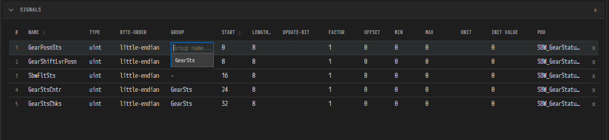
The Signals grid — the columns and the GROUP column autocomplete
Columns
The leading # column is the row number, and the last cell in each row holds a delete button (tooltip
Remove Signal). Each column has the following editing form and constraints.
| Column | Editing form | Where it is stored, and constraints |
|---|---|---|
NAME | Text | The signal name. Sortable |
TYPE | Choice (uint/sint/float) | Signal |
BYTE-ORDER | Choice (little-endian/big-endian) | Mapping |
GROUP | Autocomplete text | Signal group membership |
START | Integer | Mapping. An integer, 0 or more. Sortable |
LENGTH | Integer | Signal. An integer from 1 to 64. Sortable |
UPDATE-BIT | Integer | Mapping. An integer, 0 or more. Clear it and the value is removed |
FACTOR | Decimal | Signal. Fractions and negative values allowed |
OFFSET | Decimal | Signal |
MIN | Decimal | Signal |
MAX | Decimal | Signal |
UNIT | Text | Signal |
INIT VALUE | Decimal, or a badge | See 7.11 |
PDU | Choice | Moves the signal to another PDU. This column is hidden on the PDU tab, since there is nowhere to move it |
- Drag the right edge of a column header to change the width of every column.
- Only three columns can be sorted:
NAME,START, andLENGTH. Each click on the header cycles through no sort, ascending, descending, and no sort again. - Rows whose signal bits overlap are highlighted with a background color.
Editing a Cell and Rejected Input
- Click the cell. An input control opens in place with the existing value selected.
- Change the value and press
Enter, or move the focus away. The value is committed. - Press
Escto cancel the edit and restore the original value.
Ctrl+S (save), Ctrl+Z (undo), and Ctrl+Shift+Z or Ctrl+Y (redo) work while you are editing. In
that case the value under edit is committed first, and then the action runs. The GROUP column is the
exception: it is an autocomplete editor, so it has no such immediate commit.
If the value matches what it was when editing started, nothing is committed. Opening a cell and closing it unchanged therefore does not mark the document dirty.
The following input is rejected.
| Rejected input | Result and display |
|---|---|
NAME is empty | Not saved; the tooltip Signal name cannot be empty appears |
NAME violates the AUTOSAR rules | Not saved; the tooltip AUTOSAR naming convention: must start with a letter and contain only letters, digits, and underscores appears |
NAME duplicates an existing signal | Not saved; the tooltip Signal name "Speed" already exists appears |
START or UPDATE-BIT is negative or fractional | The edit is cancelled and the original value is restored |
LENGTH is below 1, above 64, or fractional | The edit is cancelled and the original value is restored |
| A non-numeric value in a numeric column | The edit is cancelled and the original value is restored |
GROUP violates the AUTOSAR rules | The edit is cancelled |
Leading and trailing whitespace is trimmed from names before they are saved. Entering Speed saves
Speed, for example.
GROUP Column Autocomplete
Click a GROUP cell and an input with the placeholder Group name... appears, along with a candidate
list.
- The candidates are only the groups that signals in the current frame's PDUs actually belong to. This is not the project-wide group list.
- If no group matches the name you type, a
Create "BodyGroup"entry appears; choose it to create the group and put the signal in it. - Clear the value, or enter
-, to remove the signal from its group. - A signal belongs to one group at a time. Assigning a new group removes the existing membership first.
7.10 The Preview Panel
The header of the right panel takes one of two forms, depending on the selected tab.
Bit Layout (Preview)
Shown on the frame tabs, and on the PDU tab for an I-Signal I-PDU or an NM-PDU.

The Preview panel — the bit number header row, the byte rows, the LSB/MSB markers, and the signal legend
- A bit number header row (7 6 5 4 3 2 1 0) comes first, followed by the byte rows in order:
Byte 0,Byte 1, and so on. - Each signal is assigned a color, and the legend on the right lists the signal names with their colors.
- The letter
Lmarks each signal's LSB position andMmarks its MSB position. The two positions swap with the byte order, and a 1-bit signal showsLonly. AUmarks theUPDATE-BITposition, and its tooltip readsSpeed(UB). - Overlapping bits are painted in the error color, and the tooltip names the overlapping signals, as
in
Overlap: Lock, Unlock. As soon as there is a single overlap, anOverlap (Error)entry is added to the legend. - A frame longer than 16 bytes is drawn in a compact mode that omits the letters (no
L,M, orUmarkers). - On a frame that references several PDUs, the editor inserts the PDU name as a separator and draws the layouts one after another, PDU by PDU.
An overlap is not merely a display problem; it is an error you must fix. Find the overlapping position in the Preview, then move the START value of one of the two signals so they no longer use the same bit (7.9). If there is still not enough room, check that the signal's last bit does not exceed the frame's DLC (Length for LIN) (7.7).
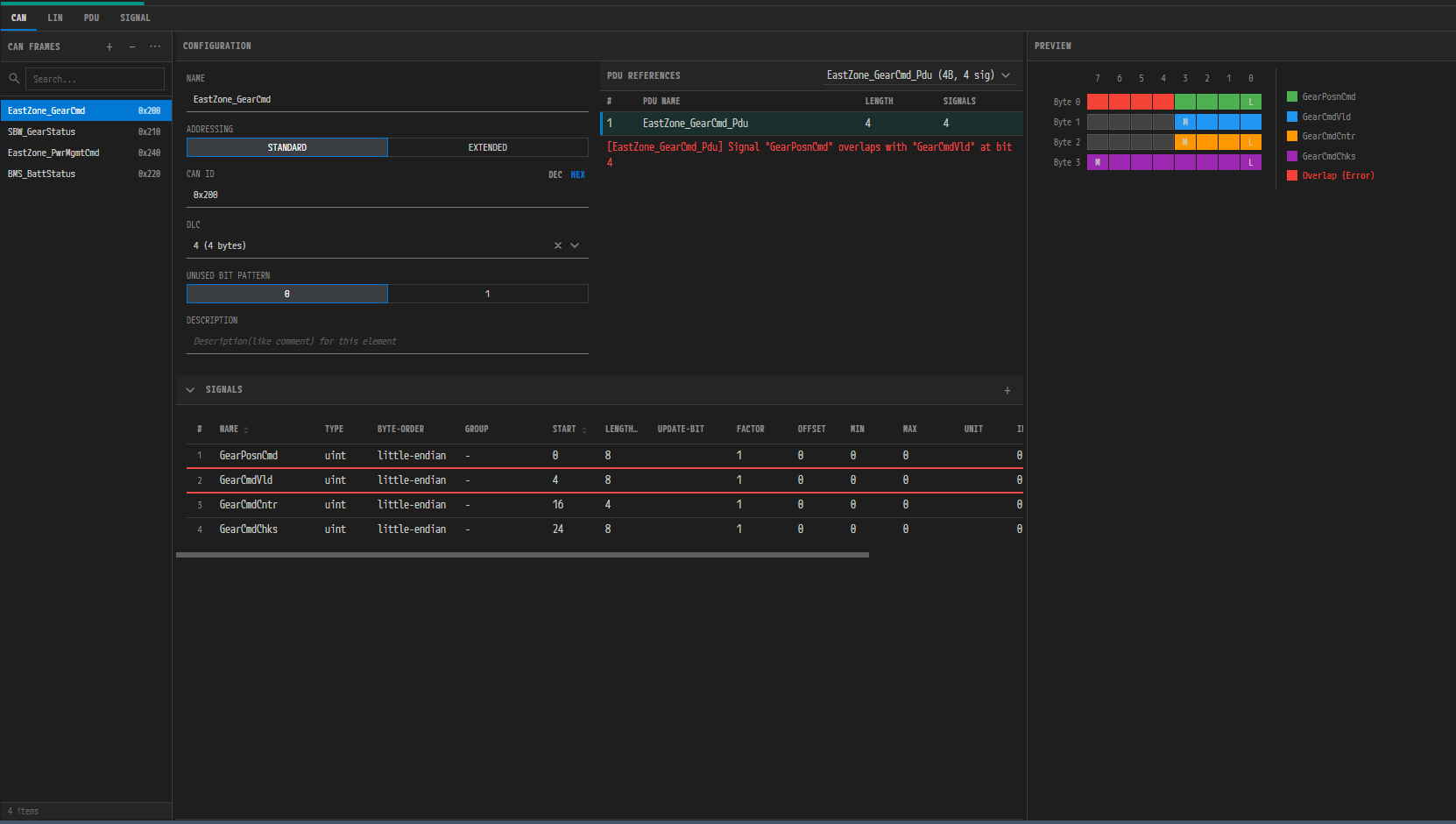
With an overlap present — the error color and the Overlap (Error) legend entry in the Preview, the validation message in PDU References, and the highlighted grid row all appear together
Signal Group Tree (Signal Groups)
A read-only tree, shown on the SIGNAL tab.
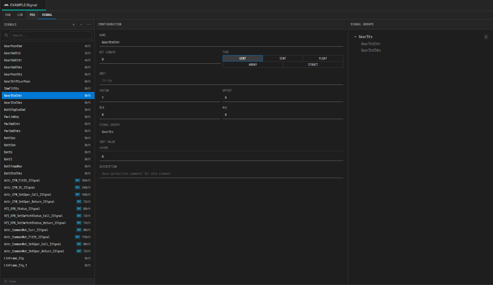
The SIGNAL tab — the signal detail form and the signal group tree on the right
- A group row shows the group name and the number of signals in it; click it to expand and collapse.
- Once expanded, click a signal name and the Configuration panel in the center moves to that signal. If the name matches no signal in the dictionary — a dangling reference left by an import — the row does not respond to clicks.
- With no groups at all,
No signal groupsappears.
7.11 Initial Values (Init Value)
A signal's initial value is edited in the project-wide value editor (ValueSpecEditor). Because a signal references no data type, the input form is derived automatically from the signal's own properties.
| Signal property | Input form |
|---|---|
| Has Text Table (enumeration) entries | A combo box. Entries appear in the form label = value |
| Bit length 1 | A 0 or 1 numeric input (not a TRUE/FALSE toggle) |
uint, n bits | An integer in the range 0 to 2^n-1 |
sint, n bits | An integer in the range -2^(n-1) to 2^(n-1)-1 |
float / array / struct | A number with no range limit |
The behavior rules are as follows.
- The model always stores a number. Choosing an enumeration label stores that entry's numeric value.
- A value outside the range is still accepted; only an error marker appears. The editor neither clamps nor reverts the value. An imported model may hold out-of-range values, and changing them arbitrarily would corrupt the source.
- Imported struct, array, and map initial values are not editable; they appear in a read-only structure viewer.
- A
trueorfalsestring initial value on a 1-bit signal is normalized to 1 or 0 on import, and the export writes only 0 or 1 (in the AUTOSAR rules, 1 ≡ true).
The INIT VALUE Column in the Grid
- When the value is a plain number, the cell is editable as it stands. If the type is
uintorsint, hovering over the cell shows a tooltip such asDerived range 0..255, and a value outside the range gets a warning marker on the cell (it is still saved).float,array, andstructhave no range, so they get neither a tooltip nor a warning. - When the value is structured, the cell becomes a badge that cannot be edited. The badge reads one of
STRUCT,ARRAY,MAP,TEXT,APP,N/A,RULE,PRESERVED, orEXPR, and the tooltip gives a one-line summary such asrecord: 3 field(s).
The value editor shares its general rules with 09. Interface Editor.
7.12 Text Table (Enumeration)
The enumeration entries a signal holds are listed in the Text Table (N entries) section of the
Configuration panel, in the form name = value.
Enumeration entries are read-only. They are created only by an ARXML or DBC import and cannot be changed in the editor.
7.13 Saving and Undo
The save and undo shortcuts are as follows.
| Action | Shortcut | Notes |
|---|---|---|
| Save | Ctrl+S | Works while the focus is inside the editor, including while you edit a grid cell |
| Undo | Ctrl+Z | |
| Redo | Ctrl+Shift+Z or Ctrl+Y |
- On save, any input in progress — a text field awaiting commit, an open cell editor — is committed first
and then the file is written, so a value is saved along with the rest even if you press
Ctrl+Simmediately after typing it. - Undo uses a single timeline shared by the whole project. The Edit menu in the header and Undo/Redo in the command palette use the same timeline (05. UI Layout and Navigation).
- With unsaved changes, a dirty marker appears next to the tab title, and closing the tab asks whether to save.
7.14 External Changes and Import
-
When another program or another feature changes the Signal model, the file watcher detects it and the editor reloads the file.
-
The automatic reload is skipped while there are unsaved changes or an edit is in progress. The following warning appears instead.
Signal file changed on disk. Keeping your unsaved edits - save to overwrite the external change.This keeps an edit in progress from being silently overwritten, and lost, by the contents on disk. To continue, either save to overwrite the external change, or revert your edits and then reload.
-
A project-wide ARXML or DBC import works differently. Before the import starts, the changes in every open editor are saved first, and when the import finishes this editor is reloaded unconditionally. Leaving a file the import overwrites unsaved would lose it on the reload.
7.15 Integration with Other Editors and Features
-
IVC editor — select a connector and the frames and PDUs defined here appear as candidates in the TX/RX Frames and TX/RX PDUs lists. Conversely, if you create an N-PDU or a DCM-I-PDU on the spot in the TP configuration dialog of the IVC editor, that PDU is added directly to this editor's live model and is recorded in the undo history.
-
System editor — renaming a signal also updates the data mapping references in the System model (
signal-name,call-signal-name). The change applies to the on-screen model if the System editor is open, and to the file on disk if it is closed. Either way it is grouped into the same undo step as the rename in the Signal editor. -
Automatic ECUC generation — module configurations such as Com and PduR take the IVC model and this model as their input (12. ECUC).
-
Validation — the constraint check results for signals and PDUs are collected in the separate Validation panel (14. Validation). The Signal editor itself has no validation panel.
-
DBC — you import a DBC file from the Import menu on the project node, where it is offered alongside ARXML. This model is where the result lands.
DBC export is not available in the current version (see 13. Import and Export).
7.16 Editing Rules Summary
- Names follow the AUTOSAR SHORT-NAME rules: the first character is a letter, and the rest are letters, digits, and underscores. The Name field in the Configuration panel does not apply a value to the model if it breaks these rules or is empty. A warning appears on screen and the previous name is kept. The rules also cap the length at 128 characters, but the editor does not enforce it, so a long name becomes a problem on ARXML export.
- Text input in the Configuration panel is committed when you stop typing or move the focus away. Hexadecimal identifier fields such as CAN ID apply a valid value immediately as you type, and revert to the previous value on focus loss if the value is out of range. Choices and toggles are committed immediately.
- Clearing Description does not store an empty string; it removes the description itself. The item — the frame, PDU, or signal — remains.
- Opening a field and closing it without changing the value does not mark the document dirty.
- The list sort and filter, the panel widths, and the scroll positions are screen state only; they are not saved to the file.