IVC Editor
What This Chapter Covers
The IVC editor is where you design the in-vehicle communication topology as a diagram. On this screen you place ECU and HPC nodes together with the connectors and controllers inside them, group them into communication clusters and physical channels, and then cable the ports of an Ethernet switch (Coupling Element) to each other. Term definitions are collected in 21. Glossary.
This chapter is for users who edit AUTOSAR network topology directly. A project must be open before you can start.
6.1 Opening the Editor and Save Locations
In the project Explorer, open the design ▸ System ▸ IVC node. The IVC editor appears as a tab.
When the editor opens it loads what you saved previously, and Ctrl+S saves back to the same place.
In a project where nothing has been created yet, the editor starts with an empty canvas and the content is created on the first save. If the saved content is damaged and cannot be read, the empty canvas is not treated as safe to save. Saving it would overwrite the original content with an empty one and lose it.
Screen layout is saved as well: node positions and sizes, the boundary position a connector is attached to, and any edge route you adjusted by hand. This layout information is not included when you export to ARXML, so node positions are recalculated if you import the exported ARXML again.
6.2 Elements You Can Work With
This editor places and edits eight kinds of element on the canvas. The following table explains each one.
| Element | Description |
|---|---|
| ECU | Classic Platform electronic control unit (ECU-INSTANCE) |
| HPC | Adaptive Platform high-performance computer (MACHINE-DESIGN) |
| Connector | Communication connector of a node (Ethernet / CAN / LIN) |
| Controller | Communication controller of a node (Ethernet / CAN / LIN Master / LIN Slave) |
| Ethernet Switch (Coupling Element) | Ethernet switch, hub, or router |
| Coupling Port | A port owned by a switch, or a port owned by an Ethernet controller |
| Communication Cluster | Communication cluster (CAN / Ethernet / LIN) |
| Physical Channel | A physical channel inside a cluster (Ethernet channels carry a VLAN ID) |
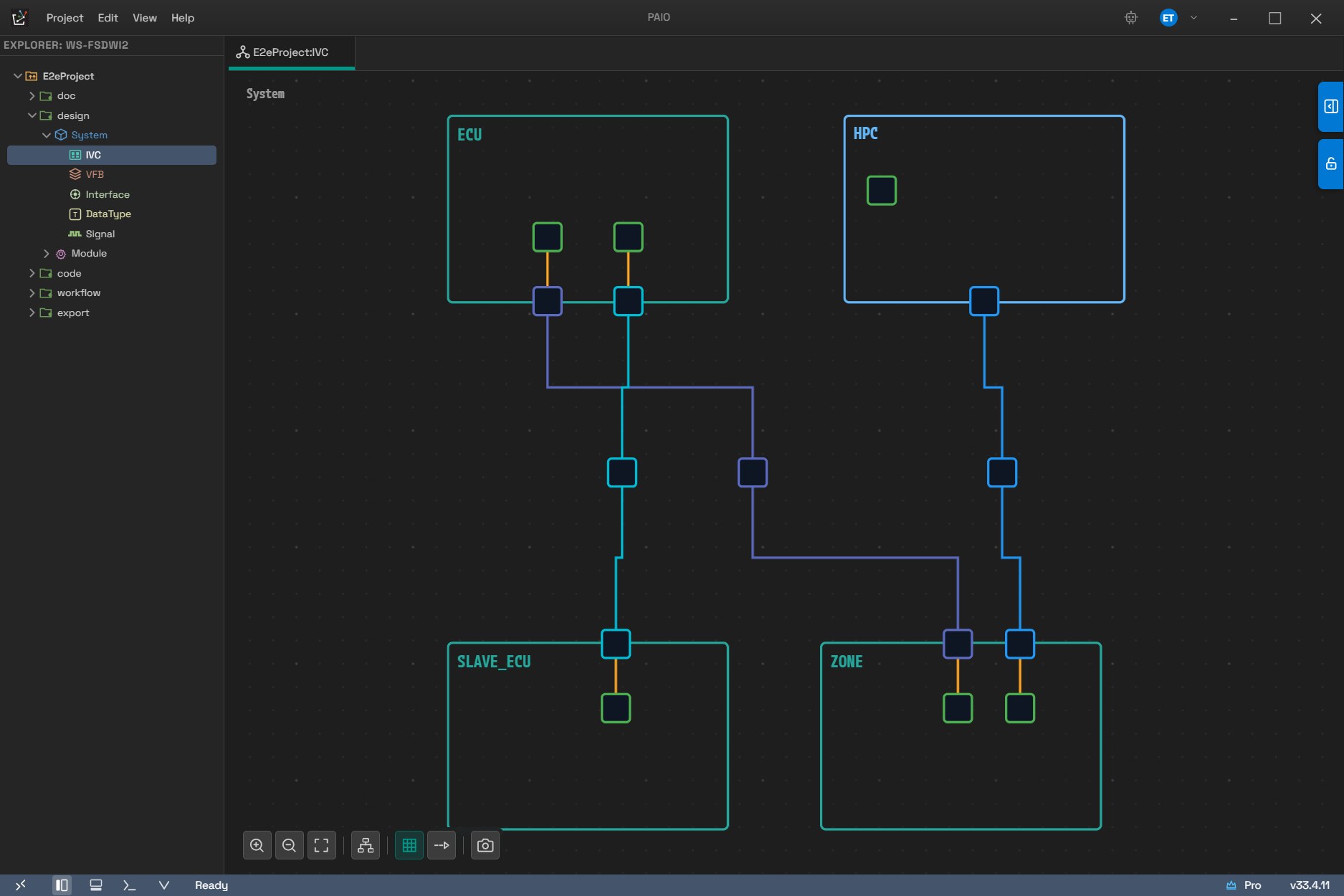
How the elements in the table look on the canvas. There are four nodes — ECU, HPC, SLAVE_ECU, and ZONE. The rectangles inside a node are Controller elements, and the rectangles straddling the node boundary are Connector elements. The short orange line joining the two is internal wiring, and the line that joins connectors outside the nodes, together with the rectangle in its middle, is a Communication Cluster. The layout has been tidied with 6.10 Automatic Layout.
FlexRay elements do not appear in this editor. Not only is there no menu item to add them (they are absent from the Add Connector / Add Controller submenus, and they do not appear grayed out either), but FlexRay connectors, controllers, and clusters that are already present from an import are filtered out before the canvas is drawn. Saving rebuilds the content from the diagram on screen alone, so if you edit and save this editor in a project that contains FlexRay, those elements disappear from the project. When you work with ARXML that contains FlexRay, it is safer not to save from the IVC editor (see 02.5).
6.3 Canvas Controls
This section covers the basic controls for moving the canvas and for selecting and moving elements.
6.3.1 Mouse
The mouse actions are as follows.
| Action | Behavior |
|---|---|
| Left-click drag on empty space | Pan the view |
| Middle-button drag | Pan the view |
Space + left-click drag | Pan the view |
| Wheel | Scroll vertically |
Shift + wheel | Scroll horizontally |
Ctrl (Cmd on macOS) + wheel | Zoom in and out around the pointer (0.1x to 4.0x) |
| Click a node | Select |
Ctrl + click | Multi-select (clicking an already selected node deselects it) |
| Drag a node | Move, snapped to the grid |
Shift + drag | Connect mode (see 6.5.5) |
| Double-click a node | Open the configuration dialog for that kind of node (see 6.7) |
| Right-click | Context menu |
Controllers and embedded switches stay inside the boundary of their parent ECU or HPC, and connectors and Coupling Ports slide along the parent's border. If you drag one outside its parent, it returns to the nearest border.
Select a single node and resize handles appear. Only three kinds of node get handles: ECU, HPC, and Ethernet Switch (Coupling Element). The handles disappear when you select more than one node. For all three, the smallest size you can drag down to is 200x100.
6.3.2 Keyboard
Shortcuts work only while the editor has focus. If you click elsewhere and focus leaves the editor, the canvas shortcuts do not respond.
| Key | Behavior |
|---|---|
Delete / Backspace | Delete the selection |
Esc | Clear the selection. While dragging a route point, cancel only that drag |
Ctrl+Z | Undo |
Ctrl+Y / Ctrl+Shift+Z | Redo |
Ctrl+A | Select all |
| Arrow keys | Move the selected nodes by 1px |
Shift + arrow keys | Move the selected nodes by 20px (one grid cell) |
Ctrl+S | Save |
Ctrl+Shift+S | Save as (file dialog) |
Ctrl+O | Load a different IVC topology into this editor through a file dialog |
Ctrl+C / Ctrl+V / Ctrl+X | No effect |
- While the cursor is in a field, canvas shortcuts such as
Delete, the arrow keys, andCtrl+Ado not work.Ctrl+S,Ctrl+Shift+S,Ctrl+O,Ctrl+Z, andCtrl+Ywork inside a field too. - Pressing
Ctrl+Zin a field first releases focus to commit the value you were editing, then undoes. The undo therefore covers one whole field edit rather than a single character. - If you move several nodes together with the arrow keys, a single undo reverts all of them.
6.3.3 Toolbar (Bottom Left of the Canvas)
The buttons on the toolbar at the bottom left of the canvas are as follows.
| Button | Behavior |
|---|---|
| Zoom In | Zoom in 1.1x. Disabled at the maximum zoom (4.0) |
| Zoom Out | Zoom out 1.1x. Disabled at the minimum zoom (0.1) |
| Fit to View | Fit the view so that every node is visible |
| Auto Layout | Run automatic layout (see 6.10) |
| Toggle Grid | Toggle the grid. On by default |
| Toggle Connector Animation | Toggle the flow animation on edges. Off by default |
| Export as PNG | Save the current diagram as a PNG file |
Export as PNG does not open a file dialog. It creates the <project>/doc/capture/ folder, saves
the file as 20260818_143015_001.png (date_time_sequence number), and shows a
Screenshot saved: <filename> toast. If the canvas holds no nodes at all, only a
No content to export warning appears and no file is created.
The grid toggle and the animation toggle are display states only, so they are not saved and they do not mark the tab as modified.
6.4 Creating Nodes
Every node's right-click menu ends with Delete. The tables below list the items that each kind of node adds.
6.4.1 Right-Clicking the Empty Canvas
Right-click the empty canvas and the following items appear.
| Item | Behavior |
|---|---|
| Add ECU | Add a Classic ECU node at the click point |
| Add HPC | Add an Adaptive HPC node at the click point |
| Add Ethernet Switch | Add a standalone Ethernet switch (Coupling Element) |
| Auto Layout | Run automatic layout |
6.4.2 Right-Clicking an ECU or HPC Node
Right-click an ECU or HPC node and the following items appear.
| Item | Submenu / Behavior |
|---|---|
| Add Connector | Ethernet · CAN · LIN |
| Add Controller | Ethernet · CAN · LIN Master · LIN Slave |
| Add Ethernet Switch (embedded) | Add a switch inside this node |
| Map Composition | Map a VFB composition to this node (see 6.6) |
| Extract ECU / Extract Machine | Extract this node alone to ARXML |
| Delete | Delete the node (Del) |
The menu name depends on the kind of node. An ECU node shows Extract ECU and an HPC node shows Extract Machine. For the extraction results and the procedure, see 13. Import and Export.
Deleting an ECU or HPC also deletes the connectors and controllers inside it, any embedded switch
and its ports, and the ports owned by its controllers. No confirmation dialog appears, so if you
delete one by mistake, press Ctrl+Z to restore it.
6.4.3 Right-Clicking an Ethernet Switch (Coupling Element) Node
Right-click an Ethernet Switch node and the following items appear.
| Item | Behavior |
|---|---|
| Add CouplingPort | Add a switch port |
| Delete | Delete the switch (Del) |
6.4.4 Right-Clicking a Controller Node
Only Ethernet controllers have an item for adding a port. The menu of a CAN or LIN controller shows Delete only.
| Item | Behavior |
|---|---|
| Add Coupling Port | Add a port owned by the controller. Disabled if one already exists |
| Delete | Delete the controller (Del) |
An Ethernet controller can own only one port. If you try to create a second one, the item is disabled and does not respond.
6.4.5 Right-Clicking a Coupling Port Node
Right-click a Coupling Port node and the following items appear.
| Item | Behavior |
|---|---|
| Connect to Port... | Pick a peer port and connect it with a physical cable (see 6.5.4) |
| Delete | Delete the port (Del) |
6.4.6 Default Names Assigned Automatically
A new node is named automatically with a number that does not collide within the same kind and the same parent. Numbering starts at 0. Only clusters have no parent, so they are counted per protocol. The formats are as follows.
| Target | Format | Example |
|---|---|---|
| ECU | ECU_<n> | ECU_0 |
| HPC | HPC_<n> | HPC_0 |
| Ethernet Switch | EthSwitch_<n> | EthSwitch_0 |
| Connector | <node>_<Ethernet|Can|Lin>_Connector_<n> | DoorEcu_Can_Connector_0 |
| Controller | <node>_<Ethernet|Can|LinMaster|LinSlave>_Controller_<n> | DoorEcu_Can_Controller_0 |
| Cluster | <CanCluster|EthernetCluster|LinCluster>_<n> | CanCluster_0 |
| Coupling Port | <parent>_Port_<n> | EthSwitch_0_Port_0 |
For a Coupling Port, <parent> is the switch name if the switch owns the port, or the controller
name if a controller owns it.
You change a name in the Name field of the properties panel. The rules are given in 6.12.
6.5 Creating Connections
This section explains how to create and remove connections between connectors, clusters, controllers, and ports.
6.5.1 From a Connector to a Cluster (Starting on the Connector Side)
A connector that is not yet connected to any cluster carries a green [+] badge. The badge disappears the moment it is connected.
- Click the connector's [+] badge. A menu opens.
- Choose Create CommunicationCluster [...] to create a new cluster of the same protocol and
connect to it immediately. The brackets hold the connector's protocol name (
Can,Ethernet,Lin). - To attach to an existing cluster, choose a cluster ▸ physical channel under Connect to Channel....
- Once connected, a line is drawn between the connector and the cluster, and the [+] badge disappears.
Connect to Channel... does not appear in the menu if there is no cluster of the same protocol.
If a cluster has several physical channels, the item expands in two steps, cluster ▸ channel; a
cluster with no channel at all appears as a single step where you pick the cluster name directly.
Ethernet channels are listed as ChannelName (VLAN: 10), and a channel with no VLAN tag shows only
the channel name.
Right-click a connector node and two items appear, Connect to Channel... and Delete. The submenu is the same as the one on the [+] badge, but this one also opens on a connector that is already connected. If you choose a different cluster, the confirmation below appears.
Connector 'DoorEcu_Can_Connector_0' is already connected to 'CanCluster_0'. Replace connection?
Confirm, and the connector leaves the channel membership of the previous cluster and joins the new
channel. These two changes are grouped into one undo step, so a single Ctrl+Z restores the
previous connection exactly.
6.5.2 From a Cluster to a Connector (Starting on the Cluster Side)
To start the connection on the cluster side, right-click the cluster node. The menu items are as follows.
| Menu | Behavior |
|---|---|
| Add Connector to Channel... | Pick a channel ▸ the connector to connect (when there is at least one channel) |
| Add Connector... | Pick the connector to connect directly (when there is no channel) |
| Add Physical Channel | Add a physical channel. Disabled once the protocol limit is reached |
| Configure... | Cluster configuration dialog (CAN / Ethernet / LIN only) |
| Delete | Delete the cluster (Del) |
Candidate connectors are listed as <node name> / <connector name>, and only connectors of the
same protocol that are not yet connected to any cluster are shown. If there is no candidate at all,
neither item appears in the menu.
The limit on the number of physical channels and the default names differ per protocol. When you create a cluster, one default channel is created with it.
| Protocol | Channel limit | First channel name | Name of each additional channel |
|---|---|---|---|
| CAN | 1 | PhysicalChannel | (limit reached) |
| LIN | 1 | PhysicalChannel | (limit reached) |
| Ethernet | No limit | PhysicalChannel | PhysicalChannel_<current channel count> |
6.5.3 Joining a Controller and a Connector (Internal Wiring)
Internal wiring is the line that joins a controller and a connector inside the same ECU. There are two ways to create it.
- Select the connector and pick a controller in the Controller field of the properties panel.
Shift+ drag from the controller to the connector (see 6.5.5).
The protocols must match (a CAN controller connects only to a CAN connector) and both must be inside the same ECU. Note that the properties panel of the controller has no field for picking a connector. In the AUTOSAR model the reference runs one way, connector ▸ controller.
6.5.4 Joining Two Ports (Physical Cable)
To join two Coupling Ports with a physical cable, proceed as follows.
- Right-click a Coupling Port node.
- Pick the peer port under Connect to Port.... A line appears between the two ports.
The candidate list shows <parent name> / <port name>, and the following ports are excluded.
- A port that is already connected to another port (a cable is point-to-point)
- The port itself, and any other port belonging to the same controller
- A port belonging to a different Ethernet cluster (applied only when the source port's cluster is known)
Other ports on the same switch remain candidates. If the source port is already connected, or if there is no candidate at all, the Connect to Port... item itself does not appear.
6.5.5 Connecting Directly with Shift + Drag
Hold Shift and drag from a node, and a preview line follows the pointer while the cursor shape
tells you the situation. The cursor shapes mean the following.
| Cursor | Meaning |
|---|---|
| Crosshair | Not over a target yet |
| Copy | This target can be connected |
| No-drop | This target cannot be connected |
You can start a drag from a Connector, Controller, Cluster, or Coupling Port. A connect drag does not start from an ECU or HPC node itself. The result for each source and target combination is as follows.
| Source ▸ Target | Result | Condition |
|---|---|---|
| Controller ▸ Connector (either direction) | Internal wiring | Same ECU, matching protocol |
| Connector ▸ Connector | Creates a new cluster that joins the two connectors | Different ECUs, matching protocol |
| Connector ▸ Cluster (either direction) | Connects the connector to the cluster | Matching protocol |
| Coupling Port ▸ Coupling Port | Physical cable | The port itself and two ports of the same controller are excluded |
| Coupling Port ▸ Controller (either direction) | Physical cable | Ethernet controllers only |
If you drop on a target that does not meet the condition, nothing happens and no message appears. The reason for the rejection is logged only to the developer console. When a connection does not work, check the protocol and the owning ECU first.
6.5.6 Removing a Connection
How you remove a connection depends on its kind.
| Connection | How to remove it |
|---|---|
| Connector - cluster | Right-click the edge ▸ Disconnect, or clear Connected Channel in the connector's properties panel |
| Controller - connector | Right-click the edge ▸ Disconnect |
| Port - port | Right-click the edge ▸ Delete Connection |
Neither the connector's [+] badge menu nor the connector's right-click menu has a Disconnect item. It used to exist but was removed because it did not work correctly. To disconnect from the connector side, clear the Connected Channel field in the properties panel.
6.5.7 Edge Right-Click Menus and Route Editing
The right-click menu of each kind of edge is as follows.
| Edge kind | Menu |
|---|---|
| Connector - cluster | Disconnect · TO STEP EDGE · TO STRAIGHT |
| Controller - connector (internal wiring) | Disconnect |
| Port - port | Delete Connection · TO STEP EDGE · TO STRAIGHT |
| Switch - cluster reference line | No menu |
- TO STEP EDGE discards the route you set by hand and returns to the automatic orthogonal route. If no route is stored, this item does not appear.
- TO STRAIGHT turns the edge into a straight line with no route points. It does not appear if the edge is already a straight line with no route points.
- Only two kinds of edge support route editing: connector-cluster and port-port. Internal wiring is always recalculated as a straight line, and the switch-cluster reference line uses the automatic route only.
Select an edge and its route point handles appear. You can drag a handle to adjust the wiring by
hand, and pressing Esc during the drag cancels only that drag and returns to the original route.
6.6 Composition Mapping (SWC - ECU)
To place a VFB composition on an ECU or HPC node, right-click the node and choose the composition from the Map Composition submenu. The submenu items mean the following.
| Item | Meaning |
|---|---|
A check mark after a name | The composition currently mapped to this node |
name (-> otherECU) | A composition already mapped to another node |
| A name with no marker | A candidate for mapping |
| Unmap | Remove the mapping (appears only when a composition is mapped) |
| Create Composition & Map | Create a composition in the VFB with the same name as this node and map it |
Create Composition & Map is disabled if a composition is already mapped to this node. For
example, if the node is DoorEcu, a composition named DoorEcu is created in the VFB.
Mapping is 1:1. Choosing an item that already carries a check mark removes the mapping, and choosing a different name moves the mapping there.
The mapping itself is recorded in the content managed by the System editor. If the System editor is open, the change is reflected there directly; if it is closed, the IVC editor records it instead. The composition that Create Composition & Map creates, by contrast, is recorded in the content managed by the VFB editor. If the VFB editor is open, the composition is created there; if it is closed, the IVC editor creates it instead.
The opposite direction — creating an ECU from a composition — is covered in 08. VFB Editor.
6.7 Configuration Dialogs
This section describes, by kind, the configuration dialog that opens when you double-click a node.
6.7.1 Which Node Opens Which Dialog
Double-click a node and the dialog for its kind opens. The dialog for each node is as follows.
| Node | Dialog title |
|---|---|
| ECU | ECU Configuration [<name>] |
| HPC | HPC Configuration [<name>] |
| Cluster (CAN/Ethernet/LIN) | Communication Cluster Configuration [<name>] |
| Ethernet Switch | Ethernet Switch Configuration [<name>] |
| Coupling Port (owned by a switch) | The switch dialog opens with that port selected |
| Coupling Port (owned by a controller) | Coupling Port Configuration [<ECU>/<port>] |
Double-clicking a Connector or Controller node does nothing. You edit the properties of those elements in the properties panel on the right.
6.7.2 Rules Common to Every Configuration Dialog
Every configuration dialog shares the following rules.
- Edits are made on a working copy. The model on the canvas does not change until you save.
- The dialog has only a Close button at the bottom and no Save button. You save with
Ctrl+S. - Pressing
Ctrl+Sapplies the working copy to the model and then saves all the way to disk. The whole operation is one unit that a single undo reverts. Saving does not close the dialog. Ctrl+Z/Ctrl+Y/Ctrl+Shift+Zrewind a separate history that is used only inside the dialog. Up to 50 steps accumulate, and nothing happens once the history is empty (it does not continue into the project history).- If there are unsaved changes, a dot (
●) appears before the title. - If there are unsaved changes when you close with
Escor Close, aDo you want to save the changes?dialog appears. Choose Save, Don't Save, or Cancel. Escfirst closes the innermost open UI (a dropdown, a menu, or an inline edit). When nothing is open, pressing it once more closes the dialog.- While the dialog is open, if another program changes the same project file, the file is not reloaded as long as the dialog holds unsaved edits. See 6.13 for details.
6.7.3 Node Configuration (ECU / HPC)
There are always three tabs. When the dialog opens, the NETWORK MANAGEMENT tab is shown first. The tabs hold the following.
| Tab | Contents |
|---|---|
| ECU or HPC | SHORT-NAME, DESCRIPTION, and, for an ECU only, SLEEP-MODE-SUPPORTED and WAKE-UP-OVER-BUS-SUPPORTED |
| NETWORK MANAGEMENT | The list of NM elements on the left, and the configuration form and diagram for the selected item on the right |
| TIME DOMAIN | The master, slave, or gateway role this node takes in a Global Time domain |
The first tab is entirely read-only. You edit the values themselves in the properties panel on the right, and a note below the tab says so.
Basic node attributes are edited in the node property panel. Shown here for reference.
The list on the left of the NETWORK MANAGEMENT tab holds one NM ECU item at the top and,
below it, one NM NODE item per cluster with a CAN or UDP badge. The diagram on the right
changes with the selection. Choose NM ECU and the NM coordinator diagram appears; choose
NM NODE and the NM state machine diagram for that cluster appears.
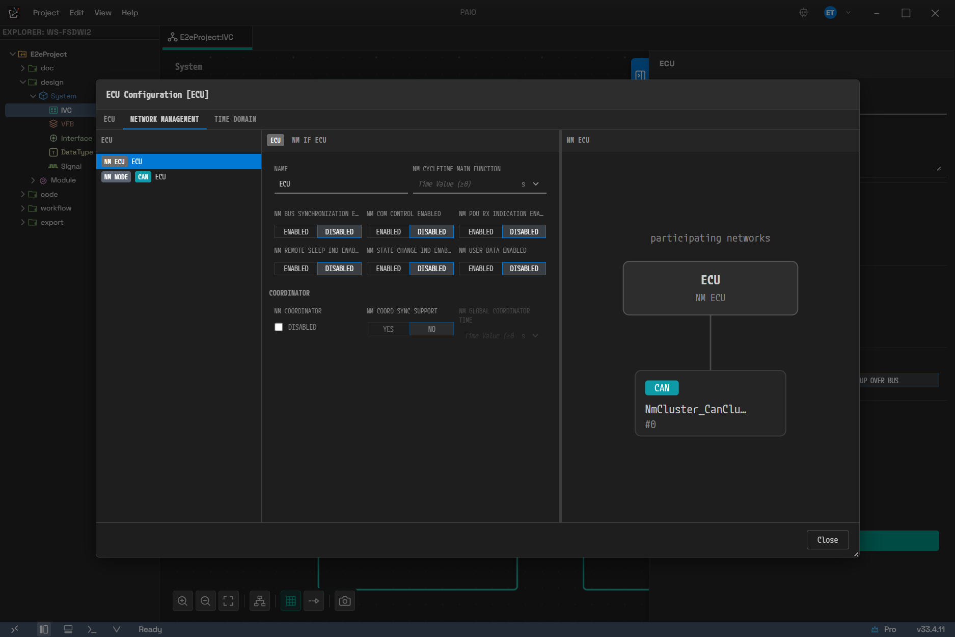
This is how the dialog opens, with the NETWORK MANAGEMENT tab first. At the top of the list on the left is NM ECU, and below it is an NM NODE carrying a CAN badge. Because NM ECU is selected, the right side shows the participating networks of this node.
You do not create the NM element list yourself; it is generated automatically from the topology. A node that is not connected to any cluster has no NM element to edit, so only the note below appears.
No NM configuration for this node yet. NM is auto-generated from topology — connect the node to a CAN/Ethernet cluster.
6.7.4 Cluster Configuration
The set of tabs depends on the protocol. The tab that opens first is always PHYSICAL CHANNEL.
| Protocol | Tabs |
|---|---|
| CAN | PHYSICAL CHANNEL · CAN NM CLUSTER · TRANSPORT PROTOCOL · TIME DOMAIN |
| Ethernet | PHYSICAL CHANNEL · UDP NM CLUSTER · TIME DOMAIN |
| LIN | PHYSICAL CHANNEL · TRANSPORT PROTOCOL |
The NM tab is named after the kind of NM the cluster has, so it appears as either CAN NM CLUSTER or UDP NM CLUSTER. The reason a tab is missing differs per protocol. LIN does not use NM, so it has no NM tab; Ethernet has no transport protocol layer configuration such as CanTp or LinTp, so it has no TRANSPORT PROTOCOL tab; and Time Sync applies only to CAN and Ethernet, so LIN has no TIME DOMAIN tab.
| Tab | Contents |
|---|---|
| PHYSICAL CHANNEL | A placeholder that has not been built yet. See the paragraph below |
| NM CLUSTER | NM cluster configuration and the NM state machine diagram |
| TRANSPORT PROTOCOL | CanTp / LinTp configuration. A configuration panel on the left plus a TP TOPOLOGY diagram on the right |
| TIME DOMAIN | Global Time domain configuration and the master/slave/gateway topology diagram |
The PHYSICAL CHANNEL tab is still empty. It has no editable items and shows only the single line below. You edit physical channels not on this tab but in the properties panel on the right when the cluster is selected (see 6.8.5).
The main choices on the TRANSPORT PROTOCOL tab are as follows. Both items are properties of a CAN TP connection (CanTpConnection).
| Item | Values |
|---|---|
| ADDRESSING FORMAT | STANDARD · EXTENDED · MIXED · MIXED29BIT · NORMALFIXED |
| TA TYPE | PHYSICAL · FUNCTIONAL |
The main choices on the TIME DOMAIN tab are as follows.
| Item | Values |
|---|---|
| MESSAGE COMPLIANCE (Ethernet) | IEEE802-1AS · IEEE802-1AS-AUTOSAR |
| CRC-SECURED (master) | SUPPORTED · NOT-SUPPORTED |
| CRC-VALIDATED (slave) | IGNORED · NOT-VALID · OPTIONAL · VALIDATED |
As with NM, the node and address items of TP are also generated automatically from the topology. The list follows along as ECUs connected to the cluster are added or removed. You cannot delete an automatically generated ECU row, but you can change the node name yourself.
6.7.5 Ethernet Switch Configuration
This dialog is a screen you drill into in two levels. The former GENERAL / PORTS / VLAN MATRIX / PORT DETAILS tab layout is gone.
[SWITCH faceplate] → [PORT pipeline (including the EGRESS editor)]
Double-click a port to go down to the next level, and move between ports with the breadcrumb at the
top (Switch > Port X) and the < > buttons. If you open the single port owned by a controller,
you start on the port screen directly, with no faceplate.
Level 1 - SWITCH (faceplate)
The switch is shown as a diagram with its ports laid out in a row. Click a port and the panel on the right shows its details; select nothing and the properties of the switch itself are shown. A check result bar sits at the bottom of the screen. Only errors are listed on this bar; warnings appear as port badges and panel hints. Click an item on the bar and the port with the problem is selected.
The panel on the right holds the following items.
| Panel | Items |
|---|---|
| Switch (nothing selected) | The SWITCH accordion with NAME · ECU (read-only) · ETHERNET CLUSTER (required) · COUPLING TYPE (required, SWITCH/HUB/ROUTER) · MAC ADDRESS LEARNING (SHARED VLAN/INDEPENDENT VLAN) · DESCRIPTION, with the PORTS (n) accordion below it |
| Port (a port selected) | The COUPLING PORT accordion with PORT NAME · CONNECTED TO · PHYSICAL LAYER TYPE · MAC LAYER TYPE (X-MII/XG-MII/XXG-MII) · PORT ROLE (HOST-PORT/STANDARD-PORT/UP-LINK-PORT) · RECEIVE ACTIVITY · NEGOTIATION (AUTO/MASTER/SLAVE) · DEFAULT VLAN (PVID), with the VLAN MEMBERSHIP · MAC ADDRESS VLAN ASSIGNMENT · WAKEUP/SLEEP accordions below it |
PORTS (n) is a read-only list with four columns, PORT · ROLE · PEER · VLAN. Click a row
and that port is selected; double-click it and you go down to the port screen. A cell with no value
shows --.
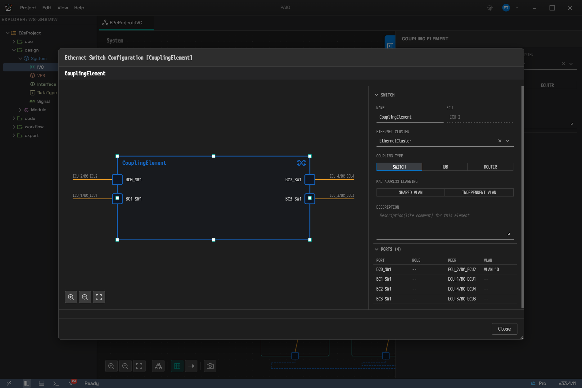
The level 1 faceplate. Four ports are drawn, each with its peer node (ECU_1/BC_ECU1 and so on), and because no port is selected the right side shows the SWITCH accordion of the switch itself. In the PORTS (4) list below it you can also see the empty ROLE · VLAN cells shown as --.
Leave a required item empty and a red underline and a message appear. No marker such as an asterisk is used.
Each line of the VLAN MEMBERSHIP list can be collapsed and expanded. Expand a line to edit the VLAN reference, the default priority, the transmission mode (TAGGED / UNTAGGED / NOT SENT), and the DHCP configuration.
MAC ADDRESS VLAN ASSIGNMENT appears only when COUPLING TYPE is SWITCH. It does not appear for
HUB or ROUTER.
On a port owned by a controller (an endpoint), RECEIVE ACTIVITY, DEFAULT VLAN (PVID), VLAN MEMBERSHIP, and MAC ADDRESS VLAN ASSIGNMENT are not drawn at all. Instead, FRAME PREEMPTION SUPPORT and PLCA (10BASE-T1S) appear. WAKEUP/SLEEP appears in both cases.
The faceplate has two right-click menus.
| Right-click target | Menu |
|---|---|
| A port | Open Port · Delete Port |
| Empty space | Add CouplingPort |
Level 2 - PORT (pipeline)
A block diagram shows the path along which one port processes frames. Click a block and the panel on the right shows its configuration while the detail area below opens. A click is only a selection; it does not change the model.
| Block | What opens in the right panel | Detail area |
|---|---|---|
| PORT | INGRESS VLAN TAG HANDLING (RECEIVE ACTIVITY FORWARD-AS-IS/DROP-UNTAGGED, DEFAULT VLAN (PVID)) · FRAME PREEMPTION SUPPORT · VLAN MEMBERSHIP · VLAN TRANSLATION | The 802.1Q frame structure diagram and the VLAN TRANSLATION table |
| PRIORITY REGENERATION | An eight-row mapping that changes a received PCP into another PCP | Mapping flow diagram |
| TRAFFIC CLASS ASSIGNMENT | Assigns a PCP to a traffic class, including the default traffic class | Assignment flow diagram |
| EGRESS | The transmission queue structure | The EGRESS editor opens directly |
- If no block is selected, the right panel shows the note
Select the port or a pipeline stage to edit it. - The TAG CHECK stage and the VLAN TRANSLATION stage, which used to be separate, have been merged into the PORT block.
- There are no enable and disable buttons. The values in the panel are the state themselves.
TRAFFIC CLASS ASSIGNMENT is drawn with a gray dashed outline and labeled
Pass-Throughwhen it has neither an assignment nor a default traffic class. PRIORITY REGENERATION and EGRESS are always drawn as active. - The 802.1Q frame structure diagram (
DA·SA· the 802.1Q tag ·TYPE·PAYLOAD) appears only in the detail area of the PORT block. - On the single port owned by a controller, the VLAN items and the PCP/TC stages are not drawn at all, because an endpoint port has no such properties in AUTOSAR. In that case only PORT and EGRESS are visible.
The EGRESS editor
The EGRESS editor is a graphical editor in which you place FIFOs, shapers, and schedulers as nodes
and join them with lines. If the structure is empty, the note
No egress structure. Right-click the canvas to add FIFOs, schedulers or a preset. appears.
| Right-click target | Menu |
|---|---|
| Empty canvas | Add FIFO · Add Scheduler (STRICT PRIORITY) · Add Scheduler (ETS) · Preset: 8 FIFOs / Strict Priority · Preset: AVB, CBS on TC6/7 · Preset: ETS weighted |
| A FIFO | Attach Shaper: CBS · Attach Shaper: ETS · Remove Shaper · Delete FIFO |
| A shaper slot | Attach Shaper: CBS · Attach Shaper: ETS · Remove Shaper |
| A scheduler | Delete Scheduler |
| An edge | TO STEP EDGE · TO STRAIGHT · DISCONNECT |
- If a FIFO already has a shaper attached, the menu names change to Replace Shaper: CBS / Replace Shaper: ETS and Remove Shaper is added. If there is no shaper, Remove Shaper does not appear.
- A preset replaces the whole existing structure. If a structure is already in place, the
confirmation
Applying a preset replaces the whole egress structure. Continue?appears first. - You can also select an element or an edge on the canvas and press
DeleteorBackspaceto delete it. - TO STEP EDGE and TO STRAIGHT in the edge menu do not disappear when the condition is not met; they remain disabled. This differs from the edge menu on the main canvas.
Select a FIFO and the SHAPER accordion appears in the right panel. KIND offers three
values, NONE · CBS · ETS. CBS also shows IDLE SLOPE (bit/s), and ETS shows
BANDWIDTH MODE (PERCENT/WEIGHT) together with the matching value field. If you change the
kind of a shaper that already holds values, the confirmation
Changing the shaper kind discards the current shaper values. Continue? appears first. Select a
scheduler and PORT SCHEDULER appears as either STRICT PRIORITY or ETS. A FIFO's
PREEMPTION has two values, EXPRESS and PREEMPTABLE; it is fixed to EXPRESS and cannot be
changed unless the port's FRAME PREEMPTION SUPPORT is on.
You cannot create an ATS (asynchronous traffic shaper) through the UI. The only paths that attach a shaper are Attach Shaper: CBS, Attach Shaper: ETS, and
CBS/ETSin the KIND segment. An imported ATS shaper is preserved in the model as it is and is labeledASYNCHRONOUSon the canvas, but the KIND segment has no matching choice, so it appears with no value selected, and there is no screen for editing the values specific to ATS (committed burst size, committed information rate). In that state, all you can touch is the shaper name andNONE(remove).
6.8 Properties Panel (Right)
Select a node or an edge and the items for its kind appear as accordions in the properties panel on the right. Edits in this panel do not pass through the license gate.
6.8.1 Layout per Node Kind
The panel layout for each kind of selection is as follows.
| Selection | Items |
|---|---|
| ECU | Name · Description · CONNECTORS · CONTROLLERS · Power Management · ECUC GENERATION |
| HPC | Name · Description · CONNECTORS · CONTROLLERS |
| Coupling Element | Name · Communication Cluster · Coupling Type · Description · COUPLING PORTS |
| Coupling Port | Name · Port Settings |
| Cluster | Name · Description · Protocol · Physical Channels · Schedule Tables (LIN) · Warnings |
- An ECU's Power Management holds two independent toggles,
SLEEP MODE SUPPORTEDandWAKE-UP OVER BUS. You can turn both on or both off. - Port Settings holds Port Role (
HOST-PORT/STANDARD-PORT/UP-LINK-PORT), Physical Layer Type, and Negotiation (AUTO/MASTER/SLAVE). Default VLAN (PVID) appears only on a port owned by a switch, because a port owned by a controller has no such property. - A cluster's Protocol section holds the baudrate only. CAN is shown in kbps and LIN in bps. An Ethernet cluster has no such section.
- The Warnings section appears only when a connector has an unresolved reference.
- The LIN SLAVES section appears when you select a LIN Master controller, not a cluster.
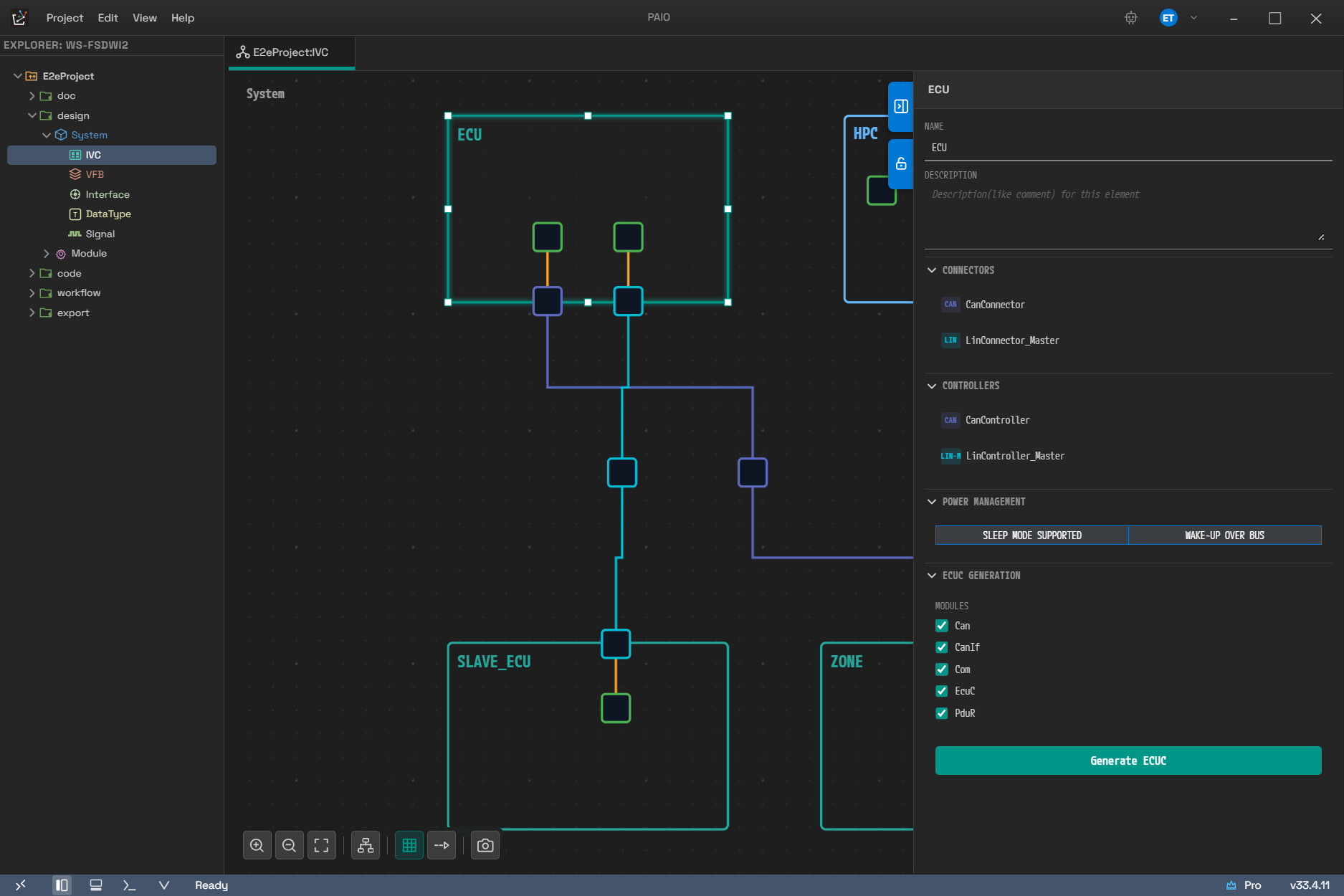
How the first row of the table (ECU) actually appears. CONNECTORS and CONTROLLERS are listed with protocol badges, the two items under POWER MANAGEMENT are independent toggles, and ECUC GENERATION at the bottom appears only when an ECU is selected.
6.8.2 When a Connector Is Selected
Select a connector and the following items appear.
| Item | Description |
|---|---|
| Name | The connector name |
| Controller | Pick a controller of the same protocol inside the same ECU |
| Connected Channel | The physical channel of the connected cluster. Clear it to remove the connection |
| Description | Description |
Further sections are added depending on the protocol.
| Protocol | Additional sections |
|---|---|
| Ethernet | Network Endpoint · Application Endpoints · Service Instances · TX PDUs · RX PDUs |
| CAN | TX Frames · RX Frames |
| LIN | LIN Connector Settings · TX Frames · RX Frames |
- Network Endpoint shows either IPv4 or IPv6, chosen with the toggle in its header, because
AUTOSAR does not use both addresses at once. The Address Source choices depend on the family that
is shown. For IPv4 they are
FIXED·AUTO-IP·DHCPv4, and for IPv6FIXED·DHCPv6·LINK-LOCAL. Keep Behavior isSTORE·FORGETfor both. - The candidate lists for TX/RX Frames and TX/RX PDUs are read from the content of the
Signal editor. Click the
+button in the section header to open the selection popup. - Application Endpoints and Service Instances exist only on an Ethernet connector. They do not appear when you select a Coupling Port.
6.8.3 When a Controller Is Selected
Every controller shows Name and Description first, and a LIN controller has one more field, a read-only Protocol. The sections below them depend on the kind.
| Controller | Sections |
|---|---|
| Ethernet | Configuration (MAC Address, MAC Layer Type, Max TX/RX Buffer Length) · COUPLING PORTS |
| CAN | CAN Controller Configuration (the header toggle switches between CAN and CAN FD) |
| LIN Master | LIN Settings · LIN SLAVES |
| LIN Slave | LIN Settings |
6.8.4 When an Edge Is Selected
Select a port-to-port edge and the Connection Info section shows First Port and Second Port as read-only values. If 10BASE-T1S multidrop (PLCA) information has been imported, the PLCA (10BASE-T1S) section appears with it. That section is read-only and offers no way to edit it, however.
Select any other edge — connector-cluster, internal wiring, or the switch-cluster reference line — and the properties panel stays empty. Those edges have no properties to edit in the panel.
6.8.5 Editing Physical Channels
Select a cluster and you edit its channels directly in the Physical Channels section. This, not the PHYSICAL CHANNEL tab of the cluster dialog, is the real editing point. The editable items are as follows.
| Item | Description |
|---|---|
| Channel Name | The channel name. Follows the AUTOSAR naming rules |
| VLAN ID (Ethernet) | 1 to 4094. Leave it empty for UNTAGGED |
| Idle Timeout (LIN) | The bus idle timeout. The field carries a unit selector and the value is stored in the model in seconds. Leaving it empty means it is not configured |
| X button | Delete the channel |
If you enter a VLAN ID outside the range and move focus away, the value is not saved and reverts to
the last saved value, with the error Must be 1..4094 or empty (UNTAGGED).
Use the + button in the section header to add a channel. Once the protocol limit (the table in
6.5.2) is reached, the + button disappears.
Below each channel is a Connected Connectors (n) line that lists the connectors connected to that
channel as <node>/<connector>. The X button on each line removes the connector from that channel.
If there are none, No connectors appears.
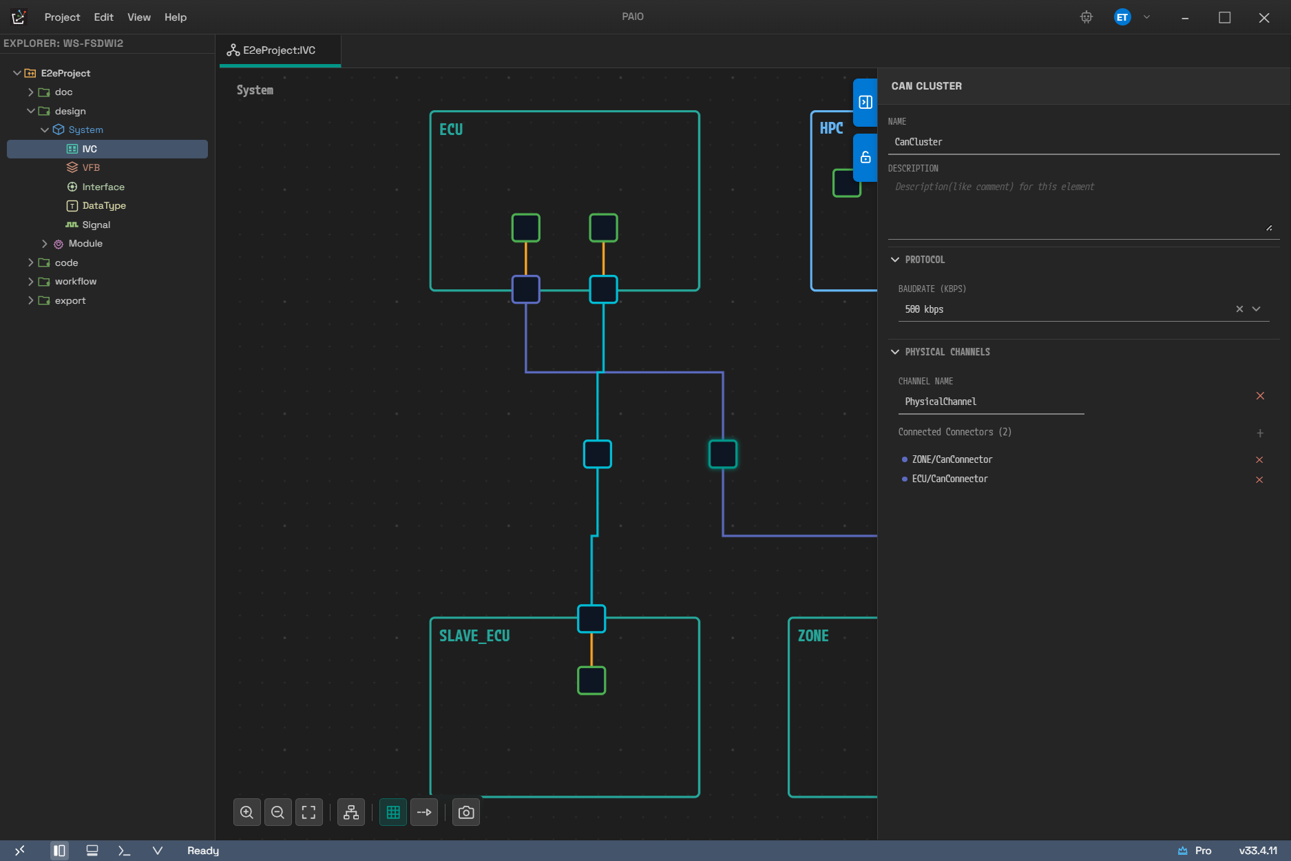
A CAN cluster selected. PROTOCOL holds the baudrate only (500 kbps), and below it PHYSICAL CHANNELS shows the channel name followed by Connected Connectors (2). The connected connectors are listed in the <node>/<connector> form, such as ZONE/CanConnector.
To add a connector to a channel, proceed as follows.
- Click the Add Connector button to the right of the
Connected Connectorsline. - Pick a connector in the
Select Connectorpopup and click Add. The connector is connected to that channel. - If there is no candidate at all, the note
No available connectors with matching protocol.appears instead of the popup.
6.9 ECUC Generation
Select an ECU node and the ECUC GENERATION section appears in the properties panel. The generation procedure is as follows.
- Check the modules to generate. All five —
Can,CanIf,Com,EcuC, andPduR— start out selected. - Click Generate ECUC. A configuration file is created for each selected module.
- On success, the toast
ECUC Configuration generated successfully: <ECU name>appears. On failure,ECUC generation failed: <reason>appears, and if an exception occurs,ECUC generation error: <reason>appears.
The prerequisites and the results are as follows.
-
Generation works only on an ECU that has at least one CAN connector. Without one, both the Generate ECUC button and the checkboxes are disabled and the note below appears.
No CAN connector configured. Please add a CAN connector first to enable ECUC generation. -
The results are created per module under
design▸Module▸Configuration▸<ECU name>. For example, if the ECU is namedDoorEcu, theCanmodule configuration is created insideConfiguration▸DoorEcu. -
If the project holds a Module Definition for the same module, its contents fill in the missing parameters. Generation also proceeds without a definition, but the result has fewer parameters filled in.
-
The generation result is recorded as a single history entry that one undo reverts. If the same content is generated again, nothing is added to the history.
-
Generation assumes there is one CAN controller. Even with several controllers, only the first CAN controller is used.
-
This section does not appear on an HPC node.
The checkbox state returns to all selected whenever the panel is redrawn. To generate only some modules, clear the checkboxes and then click Generate ECUC right away. Note that if you clear every checkbox and click, the button responds but nothing happens and no note appears.
For details, see 12. ECUC.
6.10 Automatic Layout
When there are so many nodes that tidying the layout by hand becomes difficult, use automatic layout. Run Auto Layout from the toolbar, or right-click the empty canvas ▸ Auto Layout, and a hierarchical layout based on elkjs is applied.
- If any edge route was adjusted by hand, the confirmation
N manually adjusted edge routes will be replaced by the automatic layout.appears first. Click Replace to continue, or Cancel to leave everything unchanged. - A progress dialog appears. The progress runs through
Preparing...▸Placing connectors...▸Computing layout...▸Applying layout...▸Routing edges...▸Complete!. - When it finishes, the view is fitted so that every node is visible.
- The progress dialog always appears, regardless of the number of nodes.
- Clicking Cancel while it runs stops it between stages, and in that case no layout is applied at all. Once the apply stage has begun, it is not interrupted and runs to the end.
- The entire layout result — sizes, positions, boundary offsets, and edge routes — is reverted by a single undo.
6.11 Interaction with Other Editors
Edits in the IVC editor interact with other editors at the following points.
- The mapping between an ECU or HPC and a composition is synchronized in real time with the System page and the VFB editor.
- The candidate lists of TX/RX frames and PDUs on a connector reflect the content of the Signal editor. When the Signal side changes, the lists are read again (see 07. Signal Editor).
- Renaming the system in the System editor renames the system label on the canvas as well (see 11. System Editor).
- Renaming or deleting an ECU or HPC also updates the name references in other content that is not open — System, Machine configuration, ECUC configuration, and so on — and this update is grouped into the same undo step as the IVC edit. If the System editor or the VFB editor is open, the part each owns is left untouched and the open editor updates it itself. This update is best-effort, so a failure does not block the IVC edit itself.
- Clicking an item in the validation results selects the matching node and, if needed, opens the configuration dialog on the right tab and the right field (see 14. Validation).
6.12 Naming Rules
Names of nodes, connectors, controllers, channels, and so on follow the AUTOSAR SHORT-NAME rules.
- The first character must be a letter, the rest may be letters, digits, and underscores only, and the maximum length is 128 characters.
- An empty value, a value made only of whitespace, and a value that breaks the rules are not saved to the model. The field only shows an error, and when focus leaves it, the name returns to the last saved value.
- A name is committed not while you type but when focus leaves the field or you press
Enter. The characters you type mid-edit are therefore not validated, and undo works one edit at a time. - Pressing
Escmid-edit discards the edit and restores the last saved name. The field consumes thatEsc, so the dialog does not close. - Leading and trailing whitespace is trimmed before the name is saved.
Names are handled this strictly because a name is also an identifier. If an empty name were saved, references to it from other files would be overwritten with an empty string and could not be recovered.
6.13 Items Whose Display and Behavior Differ
This section collects the points that are easy to misread from the screen alone. When something seems to behave differently from what you expect, check this table first.
| Item | Actual behavior |
|---|---|
Ctrl+C / Ctrl+V / Ctrl+X | No effect |
| A connector's Disconnect | It is not in the [+] badge menu or the connector's right-click menu. Disconnect by right-clicking the edge or by clearing Connected Channel |
A Shift+drag that does not meet the condition | Nothing happens and no error message appears |
| Saving in a configuration dialog | Only a Close button sits at the bottom. You save with Ctrl+S |
Ctrl+Z inside a dialog | It rewinds only the dialog's own history. Nothing happens once that history is empty |
| The PHYSICAL CHANNEL tab of the cluster dialog | An empty tab with only a note. You edit channels in the properties panel |
| The first tab of Node Configuration | Entirely read-only. You change the values in the properties panel |
| ATS in an EGRESS shaper | It cannot be created through the UI. Only imported values are shown and preserved, and the values specific to it cannot be edited |
| The PLCA (10BASE-T1S) section | It only shows imported values and offers no way to edit them |
| Clearing the ECUC module checkboxes | If you click Generate ECUC with none left, it silently does nothing |
| Export as PNG | It does not ask where to save and writes straight to <project>/doc/capture/ |
Ctrl+O | It does not open a project; it loads the IVC topology you pick into the current IVC editor |
If the file changes outside while you have unsaved edits, it is not reloaded and only the warning below appears. The same applies when a configuration dialog holds unsaved edits.
IVC file changed on disk. Keeping your unsaved edits - save to overwrite the external change.
This behavior exists so that the content you are editing is never discarded silently. If you want the content on disk instead, undo your edits or close the tab and open it again. If you want to keep your edits, save and overwrite.