Interface Editor
What This Chapter Covers
This chapter explains how to use the Interface editor to define the port interfaces that SWC ports reference, and to configure the deployment (SOME/IP · DDS) and service instances of an AP service interface. It covers the seven category tabs, what you edit on each tab, how interface derivation works, and what the right panel turns into in each situation.
This chapter is for users who define AUTOSAR interfaces and service deployments. A project must be open, and the license must be active to use derivation. You can define data types directly inside this screen, so you do not need to open 10. DataType Editor first.
Open design ▸ System ▸ Interface in the project Explorer and the editor appears as a tab.
9.1 Screen Layout
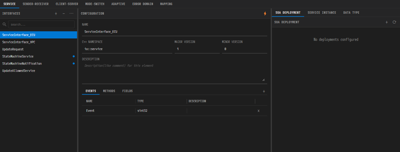
The full Interface editor. The seven category tabs sit on top, the three panels below.
Drag the borders between the three panels to adjust their widths.
The INTERFACES Panel on the Left
The elements of the left panel and what they do:
| Element | Behavior |
|---|---|
+ (Add Interface) | Adds an item that suits the current tab. On the Adaptive tab a cluster menu opens, and on the Mapping tab two input dialogs appear in turn (9.3.7) |
− (Remove Interface) | Deletes the selected item. The button is disabled while nothing is selected |
| Search box | Filters by name |
| List | While the list has focus, the up and down arrow keys move the selection |
On the Mapping tab the tooltips of the + and − buttons change to Add Mapping and
Remove Mapping.
Sort by in the ⋯ popover offers Default (Added Order) and Name (A-Z), and the
Service tab adds Version. The Service tab also shows a Filter by deployment filter
(Has SOME/IP Deployment / Has DDS Deployment / No Deployment) and a Filter by instance filter
(Has Provider / Has Consumer).
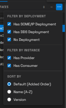
The sort and filter popover that opens from ⋯ (shown for the Service tab).
Search filters by name by default, but on the Service tab it also matches deployment names and
service instance names. When there is no item at all, Add an interface appears; when no item
matches the search and filter conditions, No matching interfaces appears. On the Mapping tab,
Add a mapping appears when there is no mapping and No matching mappings when the search returns
nothing.
The CONFIGURATION Panel in the Middle
Before you select an interface, Select an interface appears (Select a mapping on the Mapping
tab). The ⚡ button in the header performs derivation, and it appears only when the conditions are
met (9.5).
Edits made in the Interface editor are stored in two places: interface definitions go to the
Interface model, while SOA deployments and service instances go to the Service model. Both are
written together with the DataType model of the DATA TYPE panel on the right by a single Ctrl+S
(9.7). InterfaceMapping is the one exception: it is stored in the VFB model and takes effect as
soon as you edit it, without waiting for Ctrl+S (9.3.7).
9.2 The Seven Category Tabs

The seven category tabs.
What each of the seven tabs covers:
| Tab label | What it covers |
|---|---|
| Service | AP ServiceInterface + SOA deployment + service instances |
| Sender-Receiver | CP SenderReceiverInterface |
| Client-Server | CP ClientServerInterface |
| Mode-Switch | CP ModeSwitchInterface |
| Adaptive | Dedicated port interfaces grouped by AP functional cluster |
| Error Domain | AP error domains |
| Mapping | The InterfaceMapping that links an AP service interface to a CP interface |
What you edit on each tab is covered in turn in 9.3.
9.3 What You Edit on Each Category
Every tab has a free-text Description field in common. The tables below cover only the fields that differ from tab to tab. Naming follows the rules in 9.8.
9.3.1 Service
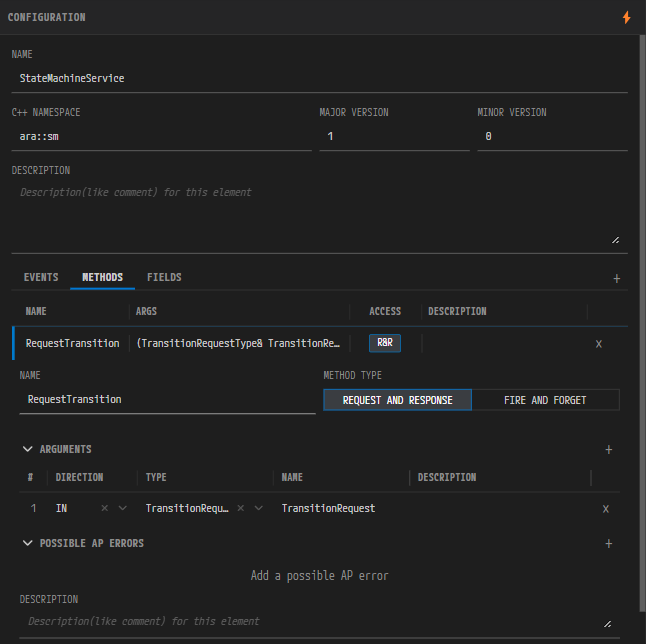
The CONFIGURATION panel of the Service tab. Expand a method on the METHODS sub-tab and ARGUMENTS and POSSIBLE AP ERRORS appear.
The fields you edit on the Service tab:
| Field | Description |
|---|---|
| Name | The interface SHORT-NAME |
| C++ Namespace | The namespace of the generated code |
| Major Version / Minor Version | The service version. An integer of 0 or more |
| The Events / Methods / Fields sub-tabs | Element definitions. The + in the header adds an item to the sub-tab that is currently open |
- The Events table has the columns
Name,Type, andDescription. Expand a row to edit Name, Type (a data type reference), and Description. When it is empty,Add an eventappears. - The Methods table has the columns
Name,Args,Access, andDescription. Expand a row to edit Name, Method Type (REQUEST AND RESPONSE / FIRE AND FORGET), the ARGUMENTS list, and the POSSIBLE AP ERRORS list. When it is empty,Add a methodappears. - POSSIBLE AP ERRORS references errors defined on the Error Domain tab. When no domain exists,
the
+button is disabled andDefine an Error Domain firstappears, so create the domain and its errors on the Error Domain tab first. Once a domain exists, an empty list showsAdd a possible AP error. - The Fields table has the columns
Name,Type,Access, andDescription. You decide here whether a field uses a Getter, a Setter, and a Notifier. When it is empty,Add a fieldappears. - An argument has one of three directions: IN, OUT, or INOUT. When there is no argument,
Add an argumentappears. - You can reorder the ARGUMENTS list. The leading number cell of each argument row is the drag handle. Hover over that cell and the cursor becomes a hand; grab it and drag up or down, and an insertion line marks the target position, where the argument lands when you drop it. The drag starts only from the handle cell, so dragging the name or type cell does not change the order. Argument order is part of the signature, so it carries through to the export result as it stands.
9.3.2 Sender-Receiver
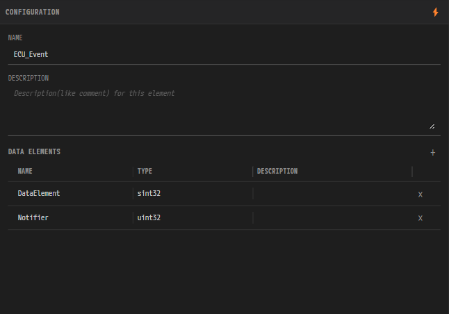
The Sender-Receiver tab. The DATA ELEMENTS table sets the name and type of each data element.
You edit Name, Description, and the DATA ELEMENTS list. The table has the columns
Name, Type, and Description, and each data element has a Name, a Type (a data type
reference), and a Description. When it is empty, Add a data element appears.
9.3.3 Client-Server
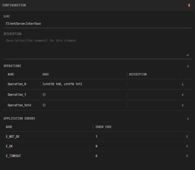
The Client-Server tab. Below OPERATIONS there is a separate APPLICATION ERRORS section that applies to the whole interface.
You edit Name, Description, and the OPERATIONS list. The table has the columns Name,
Args, and Description. Expand an operation to edit its ARGUMENTS (direction IN /
OUT / INOUT). When it is empty, Add an operation appears.
APPLICATION ERRORS applies to the whole interface rather than to an operation, and it appears as
a separate section below OPERATIONS. When there is no error, Add an application error appears.
You reorder the ARGUMENTS list the same way as on the Service tab (see 9.3.1).
9.3.4 Mode-Switch
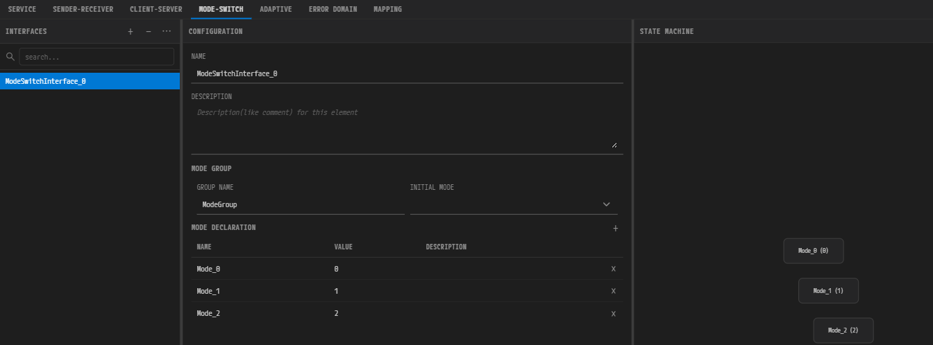
The Mode-Switch tab. Each mode declaration you add creates a node in the STATE MACHINE on the right.
The fields you edit on the Mode-Switch tab:
| Field | Description |
|---|---|
| Name | The interface SHORT-NAME |
| Group Name | The ModeDeclarationGroup name |
| Initial Mode | The initial mode |
| MODE DECLARATION | Adds and deletes mode declarations. When it is empty, Add a mode declaration appears |
On the Mode-Switch tab the right panel becomes a STATE MACHINE diagram. Mode declarations appear as nodes, and transitions are not created automatically - you draw them yourself in the diagram.
| Action | Behavior |
|---|---|
Shift + drag a node and drop it on another node | Creates a transition between the two nodes. A dashed line follows the pointer while you drag, and it turns green over a node that accepts the drop |
| Right-click a node ▸ Transition to ▸ target node | Creates the same transition from a menu |
| Right-click a transition line ▸ Delete Transition | Deletes the transition |
| Right-click empty space ▸ Add State | Adds a mode declaration |
| Right-click a node ▸ Set Initial / Delete | Sets the initial mode, or deletes the mode declaration |
| Double-click a node | Renames it in place |
Drag a node · Ctrl+wheel · wheel click (or drag the background) | Moves it · zooms · pans |
Select a node or transition line, then press Delete / Backspace | Deletes the selected mode declaration or transition |
9.3.5 Adaptive
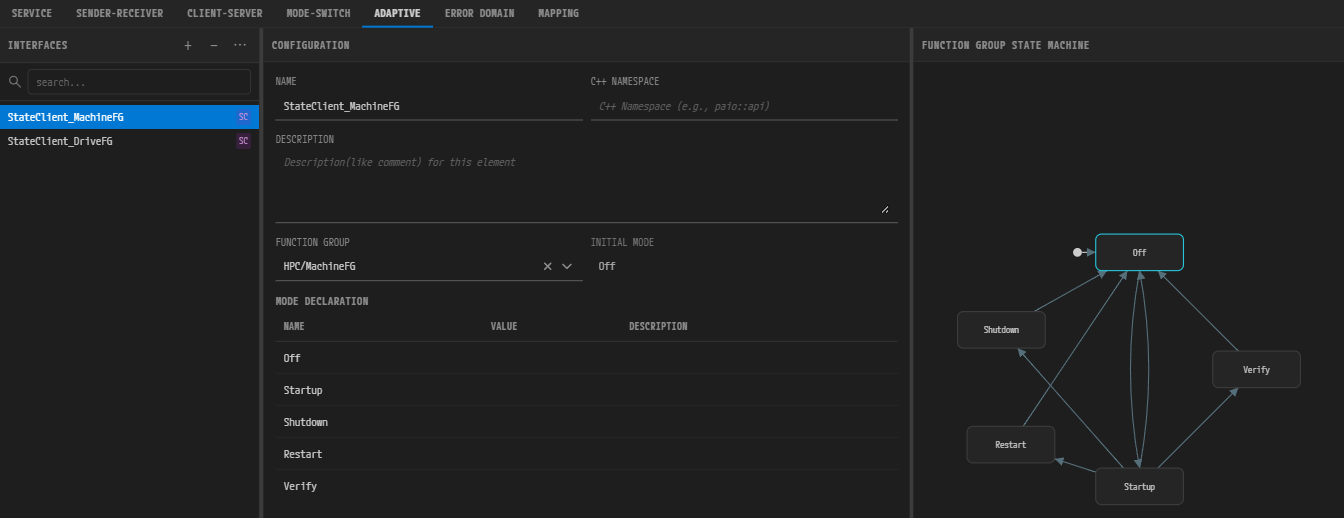
The Adaptive tab. The list on the left shows one interface per line, and a badge after the name identifies the kind.
Here you create the dedicated interfaces grouped by AP functional cluster. Click the + button and
the cluster list opens; hover over a cluster and its interface kinds expand to the side. There are
nine clusters.
| Cluster | Interface kinds |
|---|---|
| ara::log | LogAndTrace |
| ara::sm | StateClient, DiagTrigger, EmError, PhmError |
| ara::phm | PhmSupervisedEntity, PhmRecoveryNotification |
| ara::nm | NetworkManagement |
| ara::tsync | SynchronizedTimeBaseConsumer, SynchronizedTimeBaseProvider |
| ara::crypto | CryptoKeySlot, CryptoKeySlotClient, CryptoCertificate, CryptoCertificateGroup, CryptoProvider |
| ara::rds | RawDataStreamClient, RawDataStreamServer, Ieee1722RawDataStreamConsumer, Ieee1722RawDataStreamProducer |
| ara::per | PersistencyKeyValueStorage, PersistencyFileStorage |
| ara::idsm | SecurityEventReport, IdsmTimestampProvider, IdsmContextProvider, IdsmReportingModeProvider, IdsmQualifiedEventReceiver |
In the list, a kind badge follows each interface name so you can tell them apart at a glance. Hover
over any badge except LnT and a tooltip shows the full type name. The complete badge-to-interface
table is in 19.6 Adaptive Platform.
The editing form in the middle falls into four shapes depending on the kind.
| Interface | Editing form |
|---|---|
| The four SM kinds (StateClient / DiagTrigger / EmError / PhmError) | Name, C++ Namespace, Description. Only StateClient adds a Function Group reference and a read-only Initial Mode |
| PhmSupervisedEntity | Name, C++ Namespace, Description, and a CHECKPOINTS table (Name / Checkpoint ID / Description) |
| The two Persistency kinds | Name, C++ Namespace, Description, Contract Version, Minimum Sustained Size, Update Strategy, Redundancy, REDUNDANCY HANDLINGS. KeyValueStorage adds DATA ELEMENTS and DATA TYPE MAPPINGS (Add a data type mapping when empty); FileStorage adds FILE ELEMENTS and Max Number Of Files |
| All the rest (LogAndTrace, PhmRecoveryNotification, NetworkManagement, the two TSync kinds, the five Crypto kinds, the four RDS kinds, the five IDSM kinds) | The common Name / C++ Namespace / Description form. Among the Crypto kinds, only CryptoKeySlot, CryptoKeySlotClient, CryptoCertificate, and CryptoCertificateGroup add kind-specific property rows; for CryptoProvider the common form is all there is |
The Function Group of StateClient is a reference field that picks a function group defined
in the Machine Configuration dialog (8.10), in {machine}/{group} form. You cannot create a new
function group here. Once the reference resolves and that function group has at least one mode
declaration, a read-only MODE DECLARATION table (Name / Value / Description) appears
below it.
The Crypto kinds have many kind-specific properties. CryptoKeySlot, for example, has Slot Type (APPLICATION / MACHINE), Crypto Object Type (UNDEFINED / SYMMETRIC / PRIVATE / PUBLIC), Crypto Algorithm Id, Max Number Of Allowed Updates, and Key Slot Content Allowed Usages, among others.
9.3.6 Error Domain
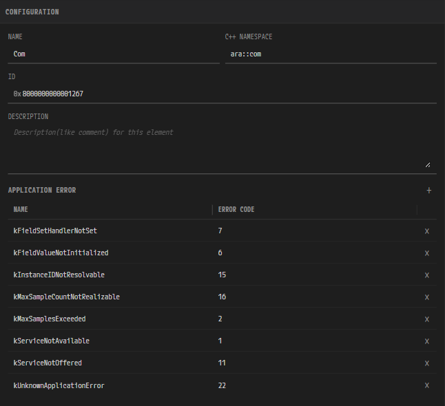
The Error Domain tab. The ID keeps a fixed 0x prefix and accepts only hexadecimal digits.
The fields you edit on the Error Domain tab:
| Field | Description |
|---|---|
| Name | The error domain SHORT-NAME |
| C++ Namespace | The namespace of the generated code |
| ID | The identifier of the error domain itself. You enter hexadecimal digits only, and the 0x prefix is fixed, so you cannot delete it |
| APPLICATION ERROR | The error list. The table has the columns Name and Error Code, with a delete button at the end of each row |
Clear the domain ID and ID is required appears; the empty value is not committed. When there
is no error, Add an application error appears.
9.3.7 Mapping
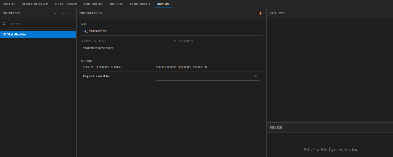
The Mapping tab. Select a mapping and the Service Interface reference and one mapping section per element kind appear.
Here you define the InterfaceMapping that links an AP service interface to a CP interface.
- Click
+and two input dialogs appear in turn. In the first (titled Add Interface Mapping, with the hintMapping name), enter a name that follows the AUTOSAR SHORT-NAME rules. In the second (with the hintService Interface (pick an existing one, or leave empty to link later)), pick an existing service interface or leave it empty. Leaving it empty creates an empty mapping that you can link later. - Select a mapping in the list and the Name and Service Interface (reference) fields appear in the middle. Below them, the CP interfaces bound to this mapping are shown read-only, split into Sender-Receiver Interface and Client-Server Interface. A name that belongs to neither appears under CP Interfaces (Unresolved).
- Once the service interface is set, one section is created for each element kind the interface has. A section for a kind with no element does not appear at all.
The columns of each section:
| Section | Left column | Right column |
|---|---|---|
| EVENTS | Service Interface Element | Sender/Receiver Interface Data Element |
| METHODS | Service Interface Element (an F&F badge marks Fire&Forget) | Client/Server Interface Operation |
| FIELDS | Service Interface Element | Sender/Receiver Data Element / Client/Server Operation |
A FIELDS row splits into sub-rows in the order Notifier → Getter → Setter, and a
sub-row appears only for a field that has that accessor. When the service interface has no element
at all, Service interface has no members appears. A reference cell with no candidate shows
No candidates.
The MAPPING tab saves to a different place. InterfaceMapping is stored in the InterfaceMapping list of the VFB model, not in the Interface model. Edits on this tab therefore touch the same target as the VFB editor: they take effect immediately when the VFB editor is open, and are written to disk when it is closed. Each edit forms one undo step.
9.4 The Right Panel
The content of the right panel changes with the active tab and the selected interface.
| Situation | Right panel |
|---|---|
| The Service / Sender-Receiver / Client-Server tabs | A sub-tab bar - SOA DEPLOYMENT / SERVICE INSTANCE / DATA TYPE |
| The Mode-Switch tab | The STATE MACHINE diagram (editable) |
| The Adaptive tab with a StateClient selected | The FUNCTION GROUP STATE MACHINE viewer (read-only) |
| Every other case (the rest of Adaptive, Error Domain, Mapping) | The embedded DataType editing panel |
The FUNCTION GROUP STATE MACHINE viewer appears as soon as you select a StateClient. If that interface has an empty Function Group reference, or one that does not match a function group in the current project, the viewer appears empty.
SOA deployments and service instances are not exclusive to the Service tab. The same sub-tab bar appears on the Sender-Receiver and Client-Server tabs, where the panel finds and shows the ServiceInterface that corresponds to that CP interface.
9.4.1 SOA DEPLOYMENT
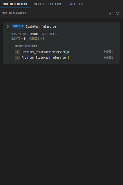
The SOA DEPLOYMENT panel. It shows the deployment kind (SOME/IP), the service ID, the version, and the provider list.
The header title is SOA DEPLOYMENT, and it has two buttons.
| Button | Behavior |
|---|---|
+ (Add Deployment) | Opens a popover to choose SOME/IP or DDS |
⟳ (Derive Signal) | Runs CP-SOA derivation again, manually |
CP-SOA derivation normally runs automatically. ⟳ is a recovery button that runs it once more by
hand. A dot appears on the button when an input to derivation changes, and it disappears once
automatic derivation finishes. The dot remains only when a license lock blocked automatic
derivation or when derivation failed.
Before you select an interface, Select a service interface appears; when there is no deployment,
No deployments configured appears. In the interface list on the left, a service interface that
has a deployment carries a colored badge, and hovering over it shows a SOME/IP Deployment or
DDS Deployment tooltip. An SR/CS interface created by derivation carries an SOC badge (tooltip
SOC (Service-oriented Communication) — seeded from a service deployment). You can still edit an
interface freely by hand even while it carries the SOC badge.
The fields of a SOME/IP Deployment:
| Field | Value range |
|---|---|
| Name | The deployment SHORT-NAME |
| Service ID | 1 to 65534. A decimal/hexadecimal toggle is available |
| Major Version | 1 to 255 |
| Minor Version | 0 or more |
| Serializer | SOME/IP or SIGNAL-BASED. Applied once to the whole deployment |
| EVENT DEPLOYMENTS | Three columns: Name, Event ID, Transport. Besides service events, a field that has a Notifier also appears here as a row. When it is empty, No events defined appears |
| METHOD DEPLOYMENTS | Three columns: Name, Method ID, Transport. Besides methods, a field that has a Getter or a Setter also appears here as a row. When it is empty, No methods defined appears |
| EVENT GROUPS | Three columns: Name, Eventgroup ID, Events, plus a delete cell at the end of the row. Add a group with the + in the header and pick its members with the Events multi-select |
The Transport cell is a per-row toggle between the two values UDP and TCP. Methods and
field Getters and Setters are always serialized with SOME/IP, regardless of the Serializer setting.
Serializer applies once to the whole deployment, so if an imported file carries a different
value per member, nothing appears selected; pick one value and the whole deployment takes it.
The fields of a DDS Deployment:
| Field | Value |
|---|---|
| Name | The deployment SHORT-NAME |
| Transport Protocol | A multi-toggle that turns SHM, UDP, and TCP on and off individually |
| Service ID | A string. Clear it and Service ID is required appears |
| Major Version | 1 to 255 |
| Minor Version | 0 or more |
| METHOD DEPLOYMENTS | Four topic names: Method Request Topic, Method Reply Topic, Field Request Topic, Field Reply Topic |
| EVENT DEPLOYMENTS | The DDS settings per event. When there is no event, No events defined appears |
A transport protocol value that PAIO does not recognize in an imported file is preserved as it is rather than dropped.
9.4.2 SERVICE INSTANCE
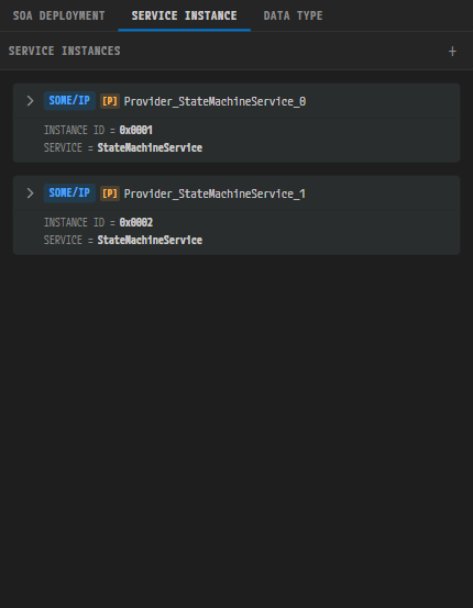
The SERVICE INSTANCE panel. A provider carries a [P] badge and a consumer a [C] badge.
The sub-tab label is SERVICE INSTANCE, while the panel header inside it reads
SERVICE INSTANCES. Add an instance with the + button. A provider carries a [P] badge and a
consumer a [C] badge. When there is no instance, No service instances configured appears.
The main fields are Name, the provider's Instance ID (an integer from 0 to 65535), the consumer's Required Instance ID and TTL, and the Service Discovery timings (Initial Delay Min/Max, Repetition Base Delay, Repetition Max, Offer Cyclic Delay, Request Response Delay Min/Max).
Required Instance ID is a free-text field. Enter ANY and it is stored as 0xFFFF;
conversely, a value of 0xFFFF is shown as ANY on screen. Otherwise only an integer in the range
0 to 65535 is accepted.
A DDS instance also has a Domain ID and QoS settings. The QoS settings are split into 14 collapsible sections - Deadline, Destination Order, Durability, Durability Service, History, Latency Budget, Lifespan, Liveliness, Ownership, Ownership Strength, Reliability, Resource Limits, Topic Data, and Transport Priority. The sections that offer a choice are these:
| QoS section | Choices |
|---|---|
| Destination Order | BY-RECEPTION-TIMESTAMP / BY-SOURCE-TIMESTAMP |
| Durability | VOLATILE / TRANSIENT-LOCAL / TRANSIENT / PERSISTENT |
| Durability Service | A history depth and KEEP-ALL / KEEP-LAST |
| History | KEEP-ALL / KEEP-LAST |
| Liveliness | AUTOMATIC / MANUAL-BY-PARTICIPANT / MANUAL-BY-TOPIC |
| Ownership | EXCLUSIVE / SHARED |
| Reliability | BEST-EFFORT / RELIABLE, plus Max Blocking Time |
The Ethernet connector properties panel of the IVC editor also has a Service Instances section, where you can check the relationship between a network endpoint and a service instance (see 06. IVC Editor 6.8.2). The section does not appear when a Coupling Port is selected.
9.4.3 DATA TYPE
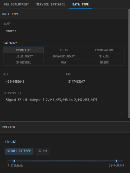
The DATA TYPE panel. You can define a data type directly inside this screen.
The interface editing screen embeds the DataType editor in a reduced form, so you can define a data type you need right here while building an interface. Your edits go to the same DataType model that the DataType editor uses. Pick the Type of an interface element and this panel selects and shows that type automatically. Which elements the reduced mode hides is covered in 10. DataType Editor 10.1.
9.5 Interface Derivation (Derive)

The derivation menu that opens from ⚡ on the Sender-Receiver tab.
The ⚡ button in the CONFIGURATION panel header performs derivation. The button is hidden
altogether when the conditions are not met. What it does depends on the tab and the selection:
| Tab / selection | Tooltip | Behavior |
|---|---|---|
| The Service tab with a ServiceInterface selected | Derive SR/CS Interface | Creates SR/CS interfaces from the service interface signature |
| The Sender-Receiver tab with an SR interface selected | Derive Service Interface | Opens a menu - Derive Service Interface / Derive Signal |
| The Client-Server tab with a CS interface selected | Derive Service Interface | Opens the Derive Service Interface input dialog directly, with no menu |
| The Mapping tab with a mapping whose service interface resolves | Derive SR/CS Interface | Creates SR/CS interfaces from the service interface the mapping points to |
In the ServiceInterface → SR/CS direction (the Service and Mapping tabs) no input dialog opens; derivation runs immediately.
- The names created are
{service interface name}_SRand{…}_CS. If a name is already taken, a number is appended, as in_1or_2. - If there is no event and no field with a Notifier, the SR interface is not created; if there is no method and no field with a Getter or a Setter, the CS interface is not created.
- An interface already derived from this service interface is left alone rather than overwritten or
duplicated. Edits you made by hand are kept as well. The test is the derivation marker, not the
name, so a
{name}_SRyou created by hand does not block derivation: a numbered interface is created alongside it.
Derive Signal in the menu targets the one selected Sender-Receiver interface. It creates signals, signal groups, and PDUs in the Signal editor and the corresponding data mappings on the System editor (see 07. Signal Editor). Its output differs from that of Derive Service Interface, which creates a service interface.
In the SR/CS → ServiceInterface direction, the Derive Service Interface input dialog opens.
- The title is Derive Service Interface and the hint is
Service Interface name (an existing name adds the members to it). - The default value is the source name with the
_SRor_CSsuffix removed. - Pick the name of an existing service interface and the elements are added to that interface; enter a new name and a new interface is created.
- If the name does not follow the AUTOSAR SHORT-NAME rules, an error message appears in place and the dialog does not proceed.
Both directions also create or fill the matching InterfaceMapping entry in the VFB model. If a
mapping that points to the same service interface already exists, no new one is created: only the
empty slots are filled, and rows you already gave a value are left alone. The whole derivation is
recorded as a single undo step spanning the Interface model and the VFB model, so one Ctrl+Z
reverts it. If the VFB model cannot be found, a warning appears and only the interfaces are created.
The ⟳ in the SOA DEPLOYMENT panel shares the name but does something else: it runs CP-SOA
derivation across the whole project again (9.4.1).
9.6 Shortcuts
The save, undo, and delete shortcuts are the ones common to the table-based model editors (see
18.4). The only difference is that a single Ctrl+S writes INTERFACE,
SERVICE, and the embedded DataType together.
Delete deletes the interface selected in the list on the left. On the Mapping tab, mappings
are managed separately from the interface selection, so the key does nothing; use the − button in
the left panel to delete a mapping. On the Mode-Switch tab, the same key also applies to a node
or transition line selected in the STATE MACHINE diagram (9.3.4), so clear the diagram selection
first when you intend to delete an interface.
9.7 Saving, Undo, and External Changes
- Interface edits are recorded across the Interface model and the Service model, but the DataType
model of the DATA TYPE panel on the right is saved together with them by a single
Ctrl+S. - The unit of undo is one edit, not one save. When an edit spans two files (derivation, for example,
or a rename that updates references), that single
Ctrl+Zreverts both; an edit that touched only one file reverts only that file. - For a text field, one edit unit lasts from gaining focus to losing it. Change several characters
of a name and a single
Ctrl+Zreverts them all at once. - When a file on disk changes externally while you have unsaved edits, PAIO does not reload it and
keeps your edits. A warning toast appears -
Interface file changed on disk. Keeping your unsaved edits - save to overwrite the external change.orService file changed on disk. Keeping your unsaved edits - save to overwrite the external change.
9.8 Naming Rules
Interface names, and the names of their child elements, follow the AUTOSAR SHORT-NAME rules: start
with a letter, then letters, digits, and underscores. Enter a name that breaks the rules and the
field turns to an orange warning showing
Must start with a letter, then letters/digits/underscores only. Clear the name and
Name is required appears in red; the empty value is not committed.
Whether a warned name is actually rejected differs from place to place. The Adaptive tab, the Persistency interfaces, the Mapping tab, and the input dialogs that appear when you create or derive an item do not accept a name that breaks the rules, and in those places a name longer than 128 characters is rejected too. The Name fields of the Service, Sender-Receiver, Client-Server, Mode-Switch, and Error Domain tabs, by contrast, only show the warning: the value itself still goes into the model, and the length is not checked.
Even on the Mode-Switch tab, the name of a MODE DECLARATION row and the names of SOME/IP and DDS deployments revert to the previous value when they break the rules. Check that no warned name remains before you export. No separate error dialog appears.
9.9 Working with the Other Editors
- When you assign an interface to a port in the VFB editor, the list defined here supplies the candidates (see 08. VFB Editor).
- Running DERIVE SR/CS INTERFACE on a Service port in the VFB creates the SR/CS interfaces and the InterfaceMapping in this editor.
- Running Derive PersistencyInterface (
⚡) on a Persistency storage in the Machine Configuration dialog (8.10) adds a Persistency interface here. - Renaming an interface also updates the SWC ports that reference it. The update happens in memory when the VFB editor is open, and by editing the SWC definition file directly when it is closed; the rename and the reference update are bound into one undo step. References in the ECUC configuration are updated the same way (see 12. ECUC).
- ARXML import and export are covered in 13. Import and Export.
- The full shortcut list is in 19. Keyboard Shortcuts.