ECUC
What This Chapter Covers
This chapter covers the two editors that handle BSW module configuration (ECUC) for the AUTOSAR Classic Platform, the feature that generates a configuration automatically from the IVC and Signal models, and the ECUC-specific import and export paths. It is written for users who work directly with the parameter structure (the definition) and the values (the configuration) of a BSW module. Before you begin, a project must be open. To use automatic generation, a CAN topology must be defined in 06. IVC Editor and frames, PDUs, and signals must be defined in 07. Signal Editor.
The following table summarizes what each editor handles and where its data is stored.
| Target | Editor | Save location |
|---|---|---|
| Module definition (schema) | Module Definition editor | Module definition |
| Module configuration values | Module Configuration editor | Module configuration |
A definition (.def) holds "which parameters exist", and a configuration (.conf) holds "what
their values are". Every configuration references exactly one definition, and one definition can
have many configurations (1:N). Whether a configuration file sits in an ECU subfolder or directly
under Configuration/ is decided by its ECU value (see 12.2.5).
These two editors behave slightly differently from the other editors. They are navigational editors that open one file at a time, so they use their own widget hierarchy. Save, undo, and redo, however, work exactly as they do in the other editors.
12.1 Module Definition Editor
12.1.1 Opening the Editor and Screen Layout
Open the Module Definition editor as follows.
- In the project Explorer, double-click the
Definitionnode underdesign ▸ Module. The Module Definition tab opens. - Right after the tab opens, no module is loaded. Select a module in the MODULE panel on the left. The tree in the middle and the properties panel on the right fill in.
The
Definitionnode does not expand. It has no chevron, and the module definition files in the folder do not appear as individual nodes in the Explorer tree. The editor's MODULE panel owns the file list.
The screen is split into left, middle, and right panes, and you can drag the dividers to change
their widths. The left panel is titled MODULE and the middle panel DEFINITION. The
properties panel on the right has no fixed title; instead it shows a header in the form
Module: <name>, Container: <name>, Parameter: <name>, or Reference: <name>, depending on
what you selected.
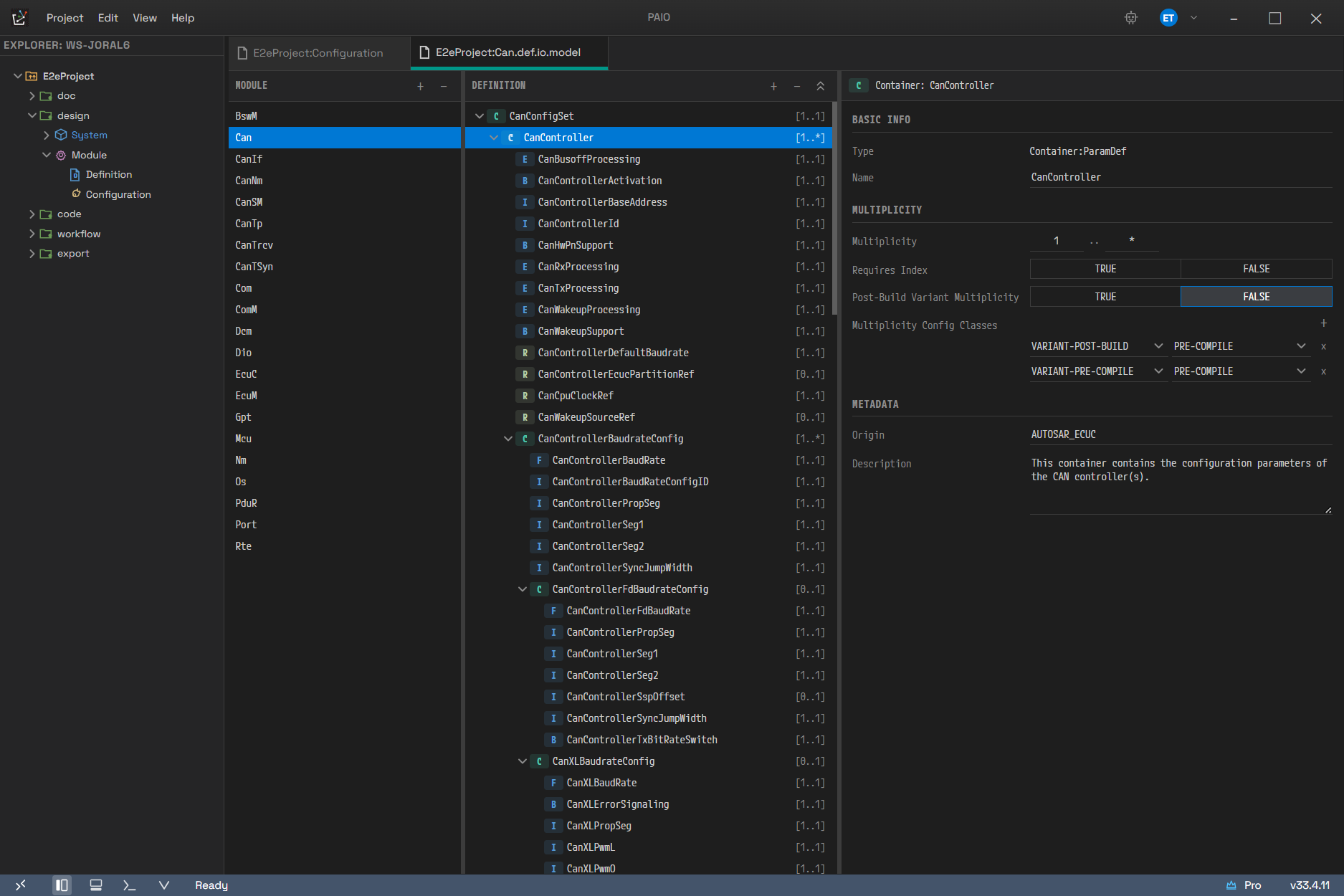
The Can module is selected in a project that imported the standard definitions. The middle tree
is fully expanded, which makes it clear at a glance that every row has the form
badge · name · [lower..upper] — C is a container, I, F, B, and E are parameter kinds,
and R is a reference. On the right, the BASIC INFO, MULTIPLICITY, and METADATA sections follow
the Container: CanController header.
12.1.2 MODULE Panel
The two buttons in the panel work as follows.
| Button | Tooltip | Action |
|---|---|---|
| + | Add Module | Opens a dialog that asks for a name and creates a module definition |
| − | Delete Module | Deletes the selected module after confirmation |
- Click + to open the Add Module Definition dialog. It has three input validation messages.
If the field is empty,
Module name is required. If the name breaks the character rule,Module name must start with a letter and contain only letters, numbers, and underscores. If the name already exists,Module "<input>" already exists. - − is clickable only while a module is selected. Clicking it opens the Delete Module
confirmation dialog (
Are you sure you want to delete module "<name>"?). - When the list is empty,
No modules found.appears. - With focus on the list, use the up and down arrow keys to move and
Enterto select. - Newly created modules and pending deletions reach the disk only when you save. In other words,
right after you create a module with + there is still no file; press
Ctrl+Sto create the module definition file. - If edits remain when you move to another module, they are saved automatically. A navigational editor holds only one file at a time, so switching without saving would discard the edits.
12.1.3 DEFINITION Tree
In this tree you edit the hierarchy of containers, parameters, and references. Every row has the
form badge · name · [lower..upper]. An unlimited upper bound appears as * on container and
reference rows and as inf on parameter rows.
There are two container badges.
| Kind | Badge |
|---|---|
| Container (ParamDef) | C |
| Container (Choice) | CH |
Parameters and references have a different badge for each type.
| Parameter type | Badge | Reference type | Badge |
|---|---|---|---|
| integer | I | reference | R |
| float | F | foreign-reference | FR |
| boolean | B | instance-reference | IR |
| enum | E | choice-reference | CR |
| string | S | symbolic-name-reference | SNR |
| function-name | FN | ||
| linker-symbol | LS | ||
| multiline-string | MS | ||
| add-info | AI |
If a parameter's Origin is not AUTOSAR_ECUC (a vendor definition), a V badge replaces the
type badge. Because V replaces the type badge, the parameter type of that row is not
distinguishable from the badge. References never get a V badge.
The toolbar has three buttons.
| Button | Tooltip | Action | Disabled when |
|---|---|---|---|
| + | Add Container | Adds a top-level container | No module is loaded |
| − | Delete | Deletes the selected container, parameter, or reference | Nothing is selected, or the module itself is selected |
| Expand icon | Expand All / Collapse All | Alternates between expanding and collapsing everything | There is no container at all |
The tree has two empty-state messages. If you have not chosen a module,
Select a module from Module Explorer. appears. If a module is open but has no container,
No containers. Click [+] to add. appears.
Row interaction works as follows. Left-click selects, a click on the chevron or a double-click expands or collapses, and right-click opens the context menu.
Context menu on a container row
| Item | Submenu |
|---|---|
| Add Container | ParamDef / Choice |
| Add Parameter | Integer / Float / Boolean / Enumeration / String / Function Name / Linker Symbol / Multiline String / Add Info |
| Add Reference | Reference / Foreign Reference / Instance Reference / Choice Reference |
| Delete | None |
The context menu on a parameter row and on a reference row contains only Delete. The add menus appear on container rows only, because a child item can be created only under the container that holds it.
Both the toolbar − and the context menu Delete delete immediately, with no confirmation
dialog. Press Ctrl+Z to undo.
The default name of a new item is NewContainer, NewParam, or NewRef, and if that name already
exists a number is appended, as in NewContainer_1. The initial values are as follows.
| Item | Initial type | Initial multiplicity | Other initial values |
|---|---|---|---|
| Container | ParamDef from the toolbar +, the chosen kind from the context menu | 0..* | None |
| Parameter | The type chosen from the menu (integer if you do not specify one) | 1..1 | integer gets Range 0..4294967295, float 0..3.4028235e38, boolean Default FALSE, and enum one Literal value1 with Default value1 |
| Reference | The kind chosen from the menu (reference if you do not specify one) | 1..1 | Destination is empty |
Symbolic Name Reference (SNR) is not in the add menu; it appears only in imported definitions.
On export it goes out as a plain Reference with REQUIRES-SYMBOLIC-NAME-VALUE set to true (if the
model explicitly contains FALSE, that value is kept). An ARXML round trip therefore normalizes
this kind to reference, and the SNR distinction survives only inside the module definition.
12.1.4 Properties Panel
Edit the properties of the selected item, section by section. The section titles are Basic Info, Multiplicity, Type Options, Reference Options, Value & Variant, Variant Support, and Metadata.
When a module is selected
| Section | Fields |
|---|---|
| Basic Info | Name, Target, Version, Description |
| Variant Support | Supported Config Variants, Post-Build Variant Support |
Target offers three choices: AUTOSAR Classic Platform, AUTOSAR Adaptive Platform, and Custom Middleware.
When a container is selected
| Section | Fields |
|---|---|
| Basic Info | Type (read-only, Container:ParamDef or Container:Choice), Name |
| Multiplicity | Multiplicity, Requires Index, Post-Build Variant Multiplicity, Multiplicity Config Classes |
| Metadata | Origin, Description |
When a parameter is selected
| Section | Fields |
|---|---|
| Basic Info | Type (read-only), Name |
| Multiplicity | Multiplicity, Requires Index, Post-Build Variant Multiplicity, Multiplicity Config Classes |
| Type Options | Per type (see the table below) |
| Value & Variant | With Auto, Symbolic Name Value, Post-Build Variant Value, Value Config Classes |
| Metadata | Origin, Description |
Type Options is composed per type as follows.
| Parameter type | Displayed label | Type Options |
|---|---|---|
| integer / float | Integer / Float | Range (min..max), Default |
| boolean | Boolean | Default (three states) |
| enum | Enumeration | Literal table, Default combo box |
| string | String | Default, Length (min..max), Regular Expression |
| function-name | Function Name | Default, Length, Regular Expression |
| linker-symbol | Linker Symbol | Default, Length, Regular Expression |
| multiline-string | Multiline String | Default (multiple lines), Length, Regular Expression |
| add-info | Add Info | None |
When a reference is selected
| Section | Fields |
|---|---|
| Basic Info | Type (read-only), Name |
| Multiplicity | Same as for a container |
| Reference Options | Per kind (see below) |
| Value & Variant | With Auto, Requires Symbolic Name Value, Post-Build Variant Value, Value Config Classes |
| Metadata | Origin, Description |
Reference Options is composed per reference kind as follows.
| Reference kind | Reference Options |
|---|---|
| Reference / Symbolic Name Reference | Destination — a search combo box over container paths |
| Choice Reference | Destinations — a table for checking several container paths |
| Foreign Reference | Destination Type — a combo box of AUTOSAR meta-types |
| Instance Reference | Destination Type plus Destination Context |
Keep the following editing rules in mind.
- Multiplicity has two fields, the lower and the upper bound. Enter
*orinfin the upper field to make it unlimited. - Three-state fields (Requires Index, With Auto, Post-Build Variant Value, and so on)
have the states unset,
TRUE, andFALSE. Unset differs fromfalse, and an unset value is not emitted on export at all. Re-exporting an imported document therefore does not add fields that were not there. - Value Config Classes and Multiplicity Config Classes let you edit variant and class pairs
on several lines. The class choices are
PRE-COMPILE,LINK,POST-BUILD, andPUBLISHED-INFORMATION, and the variant choices areVARIANT-PRE-COMPILE,VARIANT-LINK-TIME, andVARIANT-POST-BUILD. Clear the whole list to return the field to the unset state. - Supported Config Variants uses a checklist over the same three variants.
- The Destination Type combo box suggests the 62 AUTOSAR meta-types registered in the DEST catalog, but a value you type yourself is stored as-is, even if it is not in the list (this supports vendor extensions).
- If the upper bound of Range is unlimited, the field shows an
INFplaceholder instead of a value. The value is overwritten only when you actually edit it.
12.2 Module Configuration Editor
12.2.1 Opening the Editor and Screen Layout
Open the Module Configuration editor as follows.
- In the project Explorer, double-click the
Configurationnode underdesign ▸ Module. The Module Config tab opens. - Right after the tab opens, no configuration is loaded. In the MODULE panel on the left, expand a definition module and select a configuration under it. The tree in the middle and the value editing panel on the right fill in.
The
Configurationnode does not expand either. Module configuration files inside an ECU subfolder do not appear in the Explorer tree at all. The editor's MODULE panel owns the configuration list, and that panel scans both the files directly underConfiguration/and the ECU subfolders.
The middle panel is titled CONFIGURATION. The value editing panel on the right has no fixed title; depending on the selection it shows a
Module: <name>,Container: <name>, orDefinition: <name>header.
The middle panel is split top and bottom, and the lower area has two tabs, Description and Validation. Drag the divider between the two areas to change their heights.
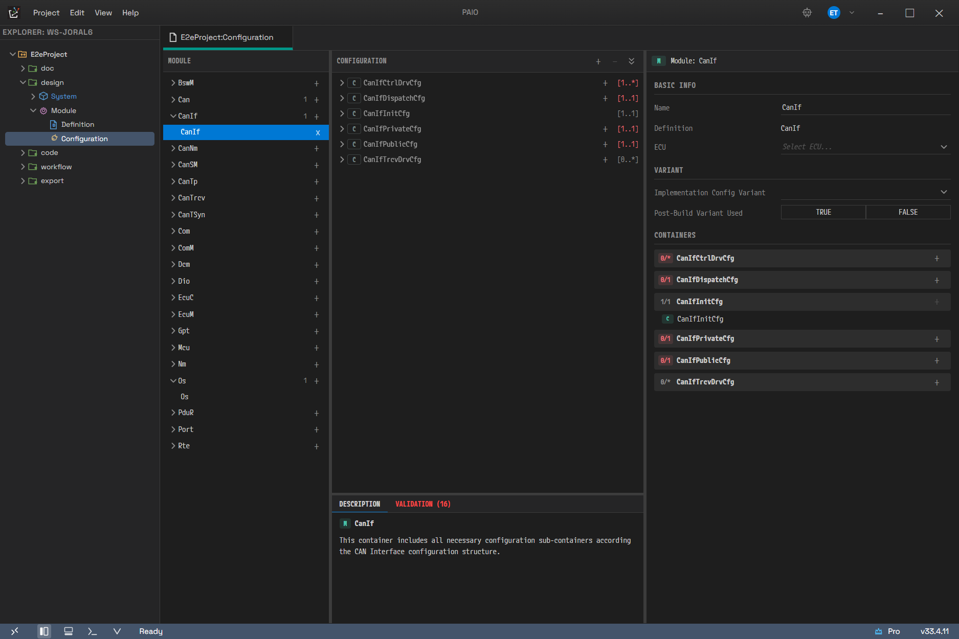
On the left, MODULE is a two-level tree with definition modules on top and their configurations
beneath. Only modules that have configurations carry a count (Can 1, CanIf 1, Os 1), so you
can see immediately where everything is. Here the CanIf configuration is selected, and the middle
pane lists that configuration's top-level containers together with their multiplicities.
12.2.2 MODULE Panel
This is a two-level tree that shows definition modules as parent rows and their configuration instances as child rows.
- Definition module row: a chevron, the module name, the configuration count (only when there is at least one configuration), and a + button. Click the row to expand or collapse it.
- Configuration row: the configuration name (in the form
name (ECU name)when an ECU value is set) and an × button. The name shown here is the name recorded inside the configuration file; the file name is used instead only when that value is missing.
The panel supports the following operations.
| Operation | Tooltip | Action |
|---|---|---|
| + on a definition module row | Create Configuration | Creates a new configuration based on that definition |
| × on a configuration row | Delete Configuration | Deletes the configuration after confirmation |
| Double-click a configuration row | None | Edits the name in place |
| Right-click a configuration row ▸ Rename | None | Edits the name in place |
| Right-click a configuration row ▸ Delete | None | Deletes the configuration after confirmation |
- A new configuration is named starting from
<module name>_0, searching for a free number. For example, clicking Create Configuration twice on theCandefinition producesCan_0andCan_1. - Deletion proceeds after you confirm the Delete Configuration dialog
(
Are you sure you want to delete "<name>"?). - A newly created configuration does not exist on disk until you save. It is therefore held
separately in memory so that a rescan of the list does not make it disappear. Press
Ctrl+Sto create the module configuration file. - Press
Enterto commit a rename andEscto cancel it. On commit, the file is renamed too, but within the same folder. A configuration that was in an ECU subfolder therefore stays in that folder. - Name collision is checked against the target folder, not the module. If ECU1 already has an Os
configuration, you cannot rename another configuration inside the
ECU1folder toOs, but ECU2's Os configuration is a different file and is not blocked. - If there is no definition at all,
No module definitions found.appears. If a given definition has no configuration,No configurationsappears. - If unsaved edits remain when you move to another configuration, they are saved automatically.
12.2.3 CONFIGURATION Tree
This tree uses the definition as its skeleton. The containers declared in the definition come first as group rows, and the actual instances attach beneath them.
- Definition group row: a
CorCHbadge (outlined style), the definition name, a + button, and the multiplicity. If the current instance count is below the lower bound, the multiplicity turns red and anAt least <n> requiredtooltip appears. - Instance row: a
Cbadge, the instance name, and[definition name].
Add an instance as follows.
- Click the + at the right of the definition group row (tooltip
Add <definition name>). An instance of that definition is created, and parameters whose definition has a default value are filled with it. - If the upper bound has been reached, or another branch of a Choice container is already selected, the + button does not appear at all.
- The name is assigned automatically. If the upper bound is 1, the definition name is used as-is;
if it is larger, the names run
<definition name>_0,<definition name>_1, and so on.
The toolbar + (Add Container) does not create an instance directly. It only scrolls to the first definition group row that can still take one. You add the instance itself with the + button on that row or with the context menu.
The toolbar has three buttons.
| Button | Tooltip | Action | Disabled when |
|---|---|---|---|
| + | Add Container | Scrolls to the first definition group that can take an instance | No configuration is loaded |
| − | Delete | Deletes the selected instance after confirmation | No container instance is selected |
| Expand icon | Expand All / Collapse All | Expands or collapses everything | The tree is empty |
Context menu on an instance row
| Item | Action |
|---|---|
| Add Container | Creates an instance chosen from the list of child container definitions |
| Rename | Opens the Rename Container dialog |
| Duplicate | Duplicates the instance |
| Delete | Deletes it after the Delete Container confirmation dialog |
The Rename Container dialog has two validation messages. If the field is empty,
Name is required. If the name breaks the character rule,
Must start with a letter, only letters/digits/underscores. The delete confirmation reads
Delete container "<name>"?.
Under a Choice container, once you have selected one branch the other branches disappear from both the menu and the + button, because only one branch of a Choice can be selected.
There are two empty-state messages. If you have not chosen a configuration,
Select a module from the list. appears. If the definition has no top-level container,
No container definitions available. appears.
12.2.4 Description Tab and Validation Tab
Both tabs at the bottom of the middle panel are read-only.
The Description tab shows the definition description of the parameter, reference, or container
you just clicked. It consists of a title line in the form badge · name · [Type, lower..upper, Origin],
a secondary line for integer and float types (in the form Range: 0..65535, Default: 1), and the
description body. If nothing is selected,
Select a parameter or reference to view its description. appears. If the definition has no
description, No description available. appears.
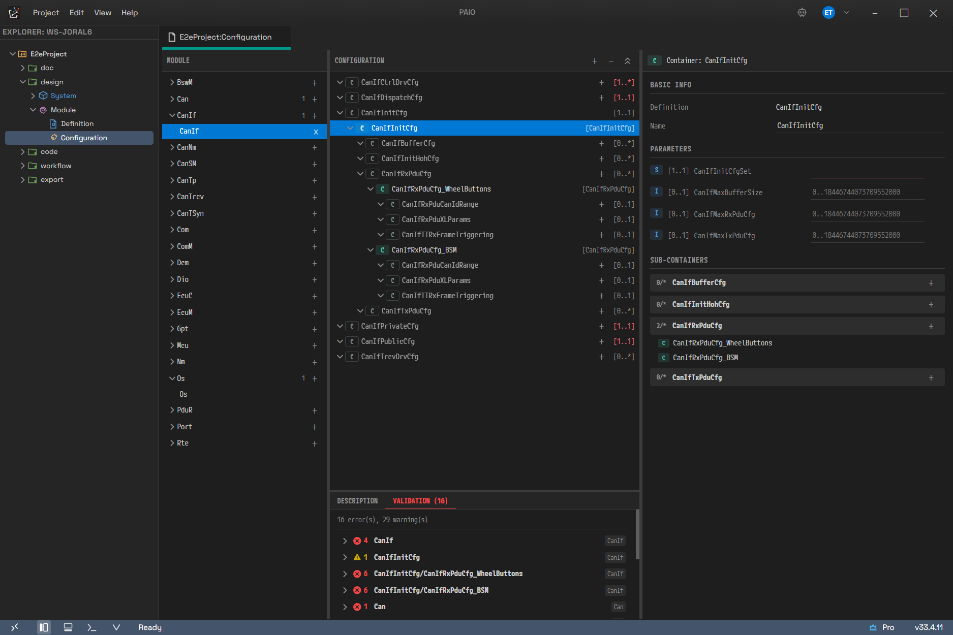
The number next to the tab name is the finding count, and opening the tab shows a total on the first
line in the form 16 error(s), 29 warning(s). Items are grouped by container path, and a badge at the
right of each line shows which module it came from. Importing the standard definitions as-is leaves
required parameters without values, exactly like this.
The Validation tab checks the whole ECUC configuration of the project and shows the result grouped
by container path. If there is no problem, No issues found. appears; otherwise an
<n> error(s), <n> warning(s) summary comes first.
The checks are as follows.
| Code | Severity | Meaning |
|---|---|---|
DEF_NOT_FOUND | warning | The definition that the instance points to was not found |
MISSING_REQUIRED_PARAM | warning | A parameter with a lower bound of 1 or more has no value |
VALUE_RANGE | error | A numeric value is outside the min/max of the definition |
ENUM_INVALID | error | An enumeration value is not in the literal list of the definition |
REF_MULT_MIN / REF_MULT_MAX | error | The number of reference values is outside the multiplicity |
REF_UNRESOLVED | warning | The target that the reference points to was not found |
REF_CONTEXT_UNRESOLVED | warning | A target pointed to by an item in the context chain of an Instance Reference was not found |
REF_DEST_MISMATCH | error | The reference target does not match the destination |
MULT_MIN_VIOLATION / MULT_MAX_VIOLATION | error | The number of container instances is outside the multiplicity |
NAME_DUPLICATE | error | Two or more containers in the same scope have the same name |
For the relationship with the project-wide validation panel, see 14. Validation.
12.2.5 Value Editing Panel
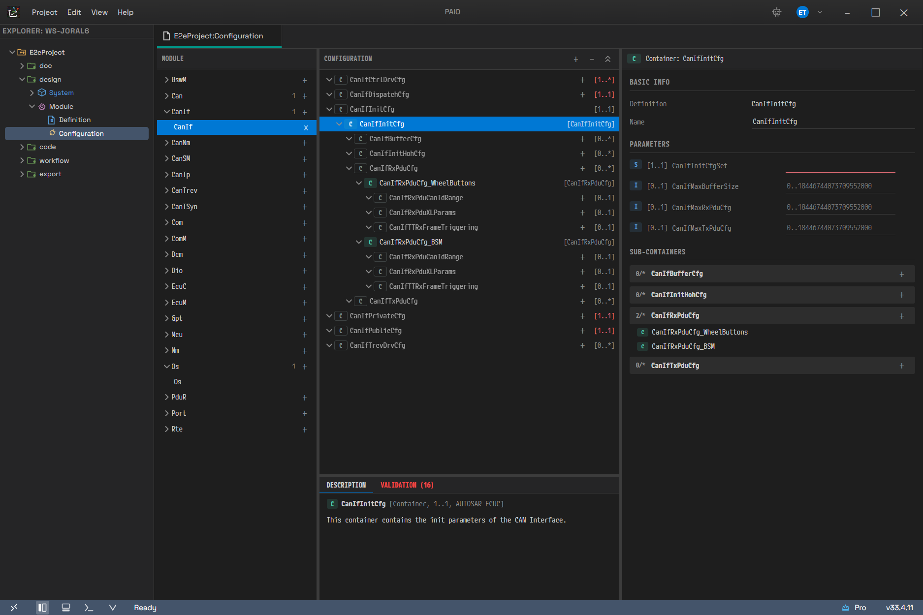
The middle tree is fully expanded and the CanIfInitCfg instance is selected. You can see the
definition groups and the actual instances distinguished in the tree — a row with [definition name]
at its right, such as CanIfRxPduCfg_WheelButtons, is an instance. On the right, PARAMETERS lists
kind badge, multiplicity, and value in that order, and SUB-CONTAINERS sits below it with
current count/upper bound.
When a module is selected (with no instance chosen in the tree), there are three sections.
| Section | Fields |
|---|---|
| Basic Info | Name, Definition (read-only), ECU, Extensions (only when present, read-only) |
| Variant | Implementation Config Variant, Post-Build Variant Used |
| Containers | Adding and deleting top-level container instances |
- Changing Name also renames the module configuration file. The old file is deleted and a new one is created, and the reference paths held by other module configurations are updated as well. All of this is a single undo unit.
- Choosing a value in the ECU combo box moves the file under
Configuration/<ECU>/. Clearing the value returns it to directly underConfiguration/. The candidate list contains only ECU node names from the IVC model; HPC nodes do not appear in it. You can clear the value with the(none)item, and you can also type a name that is not in the list. Because one project can configure the same module for several ECUs, the identity of a configuration is the<ECU>/<name>combination. - The choices for Implementation Config Variant are the Supported Config Variants of the
definition when that list is not empty, and otherwise the five standard values
(
VARIANT-PRE-COMPILE,VARIANT-LINK-TIME,VARIANT-POST-BUILD,PRECONFIGURED-CONFIGURATION,RECOMMENDED-CONFIGURATION). An imported value stays selected even if it is outside the list. Choose-to make it unset. - Post-Build Variant Used has the three states unset,
TRUE, andFALSE. Unset is not rewritten asfalse.
When a container instance is selected, the sections are Basic Info (Definition read-only and Name), Parameters, References, and Sub-Containers. The last three sections appear only when the definition declares the corresponding items. A container that declares no parameter at all, for example, gets no Parameters section.
A parameter row has the form type badge · [lower..upper] badge · (effective Config Class badge) · name · input widget · default value button. An unlimited upper bound in the multiplicity badge
appears as inf on parameter rows and as * on reference rows. Click the label to switch the
Description tab below to that parameter's description.
The input form per type is as follows.
| Parameter type | Input form |
|---|---|
| Integer / Float | Numeric input. If the definition has a range, a placeholder in the form 0..65535 appears |
| Boolean | Three-state toggle (cycling unset → TRUE → FALSE) |
| Enumeration | Combo box. Choose - to clear the value |
| String / Function Name / Linker Symbol | Single-line text input |
| Multiline String / Add Info | Multi-line text input |
- Even when no value is set, the field shows the default value from the definition if there is one.
A value visible on screen therefore does not mean a value is stored in the configuration file.
Boolean is the one exception: no default is filled in, so that unset and
FALSEstay distinguishable. - Clearing a value completely removes that parameter value from the configuration (it returns to unset).
- If the lower bound is 1 or more and the value is empty, the field is highlighted with a warning.
The undo icon button at the right of the row restores the value to the default declared in the
definition. If the definition has no default, this button is not shown (only its space remains). When
there is a default, the tooltip shows Default: <value>.
Reference rows come in two forms, depending on the multiplicity.
| Multiplicity | Form |
|---|---|
| Upper bound of 1 | A single search combo box. Clear the value with - |
| Upper bound of 2 or more, or unlimited | A trigger that opens a checklist, plus a row list of the selected values |
- In the checklist of a multiple reference, check candidates to add them, and remove them by clearing
the check or using the remove button on the row. The search field above the list doubles as free
input, so you can type a path that is not among the candidates and press
Enterto add it. This is needed because an ECUC path may fall outside the candidate set. - If the lower bound is 1 or more and there is no value at all, the underline of the trigger or the field turns red.
- A value whose target does not exist is highlighted as unresolved. Foreign and Instance References, however, are judged only when the DEST catalog can judge the meta-type; otherwise the judgment is skipped entirely (see 12.3).
- When an Instance Reference has a value, a Context Refs row appears below it. There you edit the context chain, one line at a time, with a DEST field and a VALUE field. Both fields suggest candidates but also accept free input. For a multiple reference, expand each row to edit that item's chain separately.
- The Config Class badge next to a parameter or reference is display only. It appears only when an item matches the Implementation Config Variant chosen on the module, and it does not block editing.
12.3 How References Are Resolved
This section explains how the reference candidate list is built, and when an unresolved judgment and
an automatic update happen. The candidate list of an ECUC reference is filtered by the destination
path of the definition. The path formats are as follows.
| Item | Format | Example |
|---|---|---|
| destination of a definition | module/container[/child...] | Os/OsApplication |
| Configuration instance path | module/instance[/child...] | Os/OsApplication_0 |
| ARXML DESTINATION-REF | /ARpackage.../module/container | /AUTOSAR/EcucDefs/Os/OsApplication |
- PAIO does not use AR-PACKAGE paths internally. It strips the AR-PACKAGE prefix on import and adds it
back on export (
/{EcucModuleDef}/...). - Containers in the same module and containers in other modules are all collected as candidates.
- A Choice Reference has several destinations. Each one is resolved separately, and the results are merged with duplicates removed.
The DESTINATION-TYPE (an AUTOSAR meta-type) of a Foreign or Instance Reference is linked to a target inside PAIO through an internal mapping table. The catalog registers 62 types in three grades.
| Grade | Count | Behavior |
|---|---|---|
| resolved | 16 | An element of the same name exists in PAIO. The candidate dropdown, the unresolved judgment, and rename tracking are all enabled |
| derived | 8 | The name is synthesized on export (PT_<pdu> and the like). Candidates and judgment are provided against the synthesized name |
| opaque | 38 | PAIO has no corresponding element. The value is left as free input and preserved as-is |
- A meta-type that is not in the catalog (a vendor extension) is treated as opaque, not as an error.
- Opaque values, and older imported values that have no
destinformation, are not judged. This avoids raising a warning on a guess. - The severity of an unresolved judgment is a warning for both resolved and derived.
- The stored form is the absolute path with only the leading slash removed, and it is written back unchanged on export. The catalog takes part only when a value is created and when it is judged; it does not change the export path.
- Renaming an element in another model automatically updates the corresponding reference value even in
closed
.conffiles. There are seven kinds of target: Signal, IVC, SWC, Interface, DataType, VFB, and other ECUC configurations. The update happens only when both thedestmeta-type recorded in the value and the name match, so older imported values withoutdestare left untouched.
12.4 Automatic ECUC Generation
Create the CAN-based BSW module configuration automatically from the IVC and Signal models.
12.4.1 How to Run It
- Open the 06. IVC Editor.
- Select the target ECU node. The ECUC GENERATION accordion appears in the properties panel on the right. This section exists on ECU nodes only, not on HPC nodes.
- Under MODULES, check the modules to generate. All five (
Can,CanIf,Com,EcuC,PduR) start out checked. - Click Generate ECUC. When generation finishes, the notification
ECUC Configuration generated successfully: <ECU name>appears at the bottom of the screen. On failure you getECUC generation failed: <reason>, and if an exception occurs during processing,ECUC generation error: <message>. - Open the Module Configuration editor and expand the corresponding definition module in the
MODULE panel. The new configuration appears in the form
<module> (<ECU name>).
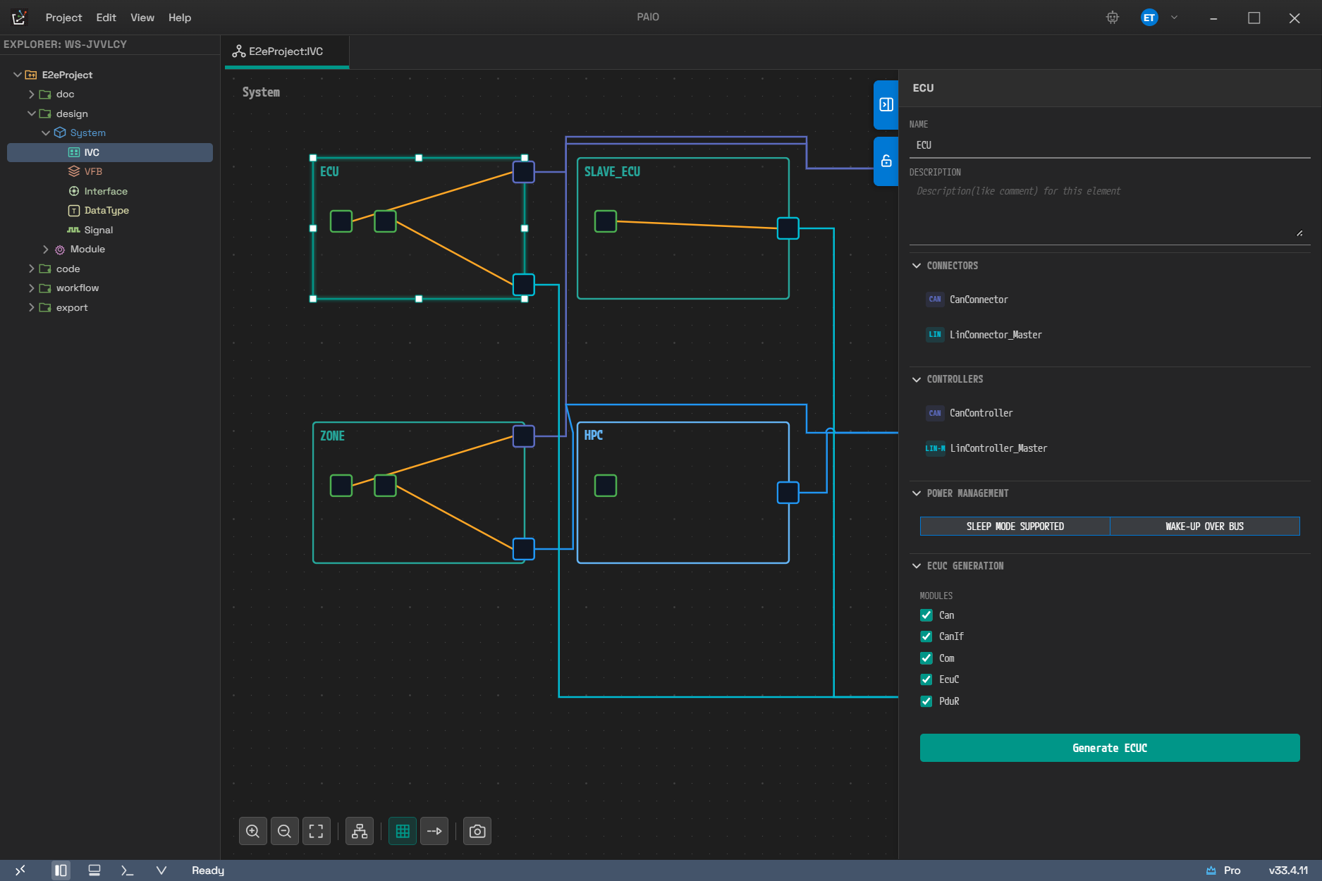
Select an ECU node on the IVC canvas and this section appears at the very bottom of the properties
panel on the right. The checkboxes and the Generate ECUC button below are live only when
CONNECTORS above holds a connector with a CAN badge. All five modules checked is the default state.
12.4.2 Prerequisites and the Disabled State
To run generation, the following conditions must be met.
| Condition | How to check it |
|---|---|
| The target ECU must have a CAN protocol connector | Without one, the checkboxes and the Generate ECUC button are all disabled |
| At least one module must be checked | Clear them all and clicking the button does nothing |
Without a CAN connector, a warning box appears at the top of the section:
No CAN connector configured. Please add a CAN connector first to enable ECUC generation.
12.4.3 Generation Results
- The result is saved as module configurations under
design▸Module▸Configuration▸<ECU name>. - Generating for the same ECU again overwrites the existing files. The whole regeneration is recorded
as a single undo unit (
Generate ECUC: <ECU name>), so you can revert it withCtrl+Z. Files whose content did not change are not recorded in the history. - If a definition file (a module definition) exists, parameters and references missing from the generated result are filled in from that definition.
12.4.4 Limits and Cautions
- Generation assumes exactly one CAN controller. Multiple CAN configurations are not supported in the current version.
- A missing definition file does not block generation. Instead, the fill-in step is skipped and the
warning
Definition file not found for <module>. Generated config may have incomplete parameters.is produced. A warning is also produced when there is no frame and when there is no CAN controller.
The warning strings produced during generation are not shown on screen in the current version. The notification is a single success or failure line. So even when a missing definition file leaves a configuration with unfilled parameters, the screen reports nothing but success. After generation it is safer to check the result in the Validation tab of the Module Configuration editor.
There is no progress indicator either. On a large model it can therefore look as if nothing is happening until the notification appears.
12.5 ECUC Import and Export
12.5.1 Import
There are two ways to bring in ECUC.
| Method | Scope |
|---|---|
| Right-click the project node ▸ Import | Full ARXML import. Processes ECUC-MODULE-DEF and ECUC-MODULE-CONFIGURATION-VALUES together |
Right-click the Module ▸ Configuration node ▸ Import ECUC Configuration | ECUC-only import. Processes only the ECUC-MODULE-DEF and ECUC-MODULE-CONFIGURATION-VALUES in the chosen file |
The Module ▸ Definition node has no import menu. Use Import ECUC Configuration above to bring in
definitions on their own as well.
The ECUC step of a full import
- Once model file creation finishes,
ECUC-MODULE-DEFis looked up in the ARXML and written as module definitions. This step does not go through the conflict dialog; it overwrites a definition file of the same name. ECUC-MODULE-CONFIGURATION-VALUESis processed next. Because definitions come in first, a configuration can also be paired with a definition in the same file.- Module configurations that already exist are handled in the same conflict resolution dialog as the other models.
- Modules skipped because no definition was found, modules rejected because the structure did not match, and parsing warnings are all included in the import result.
The ECUC-only import procedure
- Right-click the
design ▸ Module ▸ Configurationnode and choose Import ECUC Configuration. - Choose an
.arxmlfile in the file selection dialog (Select ARXML File to Import ECUC Configuration). The Import ECUC Configuration progress dialog appears. - If there is a conflict with an existing file, the conflict resolution dialog appears. Even if you cancel, the non-conflicting configurations already written remain.
- The result appears.
- On full success, the notification
ECUC Configuration Import Complete — imported <n> module configuration(s).appears. - If only part of it comes in, the ECUC Configuration Import — Partial dialog appears and shows
the
Skipped — Module Definition not found:andRejected — definition mismatch:lists together with the reasons. - On failure, the ECUC Configuration Import Failed dialog shows the error.
- On full success, the notification
- The Explorer refreshes, and any open ECUC editor re-reads its cache.
Keep the following in mind about the ECUC-only import.
- This path also brings in definitions first. If the chosen file contains
ECUC-MODULE-DEF, it is written as module definitions first and the configuration values are processed afterwards. This definition write does not go through the conflict dialog; it overwrites a file of the same name. That is what makes it possible to pair a definition and a configuration contained in one file. - If a module's definition exists neither in the project nor in that file, its configuration is skipped. Without the definition there is no way to judge which parameters are valid.
- A configuration whose structure does not match the definition is rejected together with the reason.
Parameters and references attached directly to the module in ECUC-MODULE-DEF are discarded deliberately. The standard schema has no place for them, so keeping them would make the export violate the schema. Unsupported
ECUC-*-DEFelements are ignored for the same reason.Discarded items are not shown on screen in any path in the current version. The full import puts this warning into its result data in the form
[<file name>] ...and the dedicated import records warnings too, but neither result screen draws the warning list. The full import shows only the single lineImport complete: <n> elements imported from <m> file(s), and the dedicated import shows only the skipped and rejected lists. To find out what was discarded, open the imported module definition in the Module Definition editor and inspect it yourself.
12.5.2 Export
Right-click the project node and run Export to export ECUC along with everything else. For the detailed procedure, see 13. Import and Export.
The files produced and the absolute paths of their elements are as follows.
| File | Content | Absolute path of the elements |
|---|---|---|
<Project>_EcucModuleDef.arxml | Module definitions plus EcucDefinitionCollection | /EcucModuleDef/<module> |
<Project>_EcucConfVal.arxml | Module configuration values | /EcucConfigVal/<ECU name>/<module> |
The AR-PACKAGEs themselves are one EcucModuleDef, plus EcucConfigVal and the ECU name packages
beneath it. Module elements sit inside the ELEMENTS of that package, which is why the absolute paths
come out as in the table above.
- A configuration with no ECU assigned sits directly under the
EcucConfigValpackage. - Which ECU or HPC a configuration belongs to is recorded not only in the AR-PACKAGE name but also in
the ADMIN-DATA of each configuration element (SDG GID
IO-ECUC-CONFIG-TO-ECU-MAPPING). Classic nodes point to an ECU-INSTANCE, and HPCs to a MACHINE-DESIGN. On import, if this SDG is present its name is used as the owning ECU, so ownership survives even when a vendor tool groups the packages differently. - Conversely, when you import an external ARXML without this SDG, the owning ECU is inferred from the AR-PACKAGE name. In a vendor file where every configuration sits in one package, that package name becomes the ECU folder name, which may not match the real ECU. In that case ECU Extract cannot pick out the configuration.
- In ECU Extract mode, all module definitions are exported but only the configurations of that ECU. All definitions are included because the DEFINITION-REF that the ECU's configurations reference must always resolve.
12.6 Editing Rules and Shortcuts
12.6.1 Naming Rules
- Module, container, parameter, and reference names follow the AUTOSAR SHORT-NAME rule (start with a letter, letters, digits, and underscores only, at most 128 characters). A value that breaks the rule is not stored in the model: the field reverts to the last accepted value and a one-line error message appears.
- A change that collides with another name under the same parent is rejected as well, because two items with the same name could not be told apart. This duplicate check applies to containers, parameters, and references in the Module Definition editor.
- When you rename a container instance in the Module Configuration editor, the reference value paths that pointed to that instance within the same configuration are updated with it.
- When you rename a module in the Module Definition editor, the module definition file is renamed with
it and the definition links of every module configuration are updated. If a module of that name
already exists, the change is rejected and the notification
A module named '<name>' already existsappears. - When you rename a configuration in the Module Configuration editor, the module configuration file is renamed with it. The naming rule check, however, happens only in the Name field of the value editing panel. The path where you double-click a row in the MODULE panel blocks only an empty name and a name collision within the same folder; it does not check the AUTOSAR SHORT-NAME rule. It is safer to use a name that follows the rule.
- When you rename something in another editor, even the Foreign and Instance Reference values in closed
.conffiles are updated automatically, and any open ECUC editor reflects the change immediately. The conditions are listed in 12.3.
12.6.2 Shortcuts
The two editors share most of their shortcuts. Only Ctrl+D and F2 are specific to the Module
Configuration editor.
| Operation | Shortcut | Notes |
|---|---|---|
| Save | Ctrl+S | Commits the value of the field being edited first, then saves |
| Undo | Ctrl+Z | |
| Redo | Ctrl+Y or Ctrl+Shift+Z | |
| Delete the selection | Delete or Backspace | Does nothing while a field has focus |
| Duplicate a container instance | Ctrl+D | Module Configuration editor only |
| Move focus to the name field | F2 | Module Configuration editor only. Selects the first field of the right-hand panel |
Deleteremoves containers, parameters, and references in the Module Definition editor, and container instances in the Module Configuration editor. The module itself cannot be deleted with this key.- Deleting with the
Deletekey shows no confirmation dialog. Only deleting with the toolbar − or the context menu Delete in the Module Configuration editor goes through theDelete container "<name>"?confirmation. - The Project ▸ Save, Project ▸ Save All, and Edit ▸ Undo/Redo menus run the same actions.
12.6.3 External Changes
If another tool changes a .def or .conf file that is being edited, both editors detect it. If
unsaved edits remain, the content on disk is not loaded and only a warning appears.
- Module Definition editor:
Module definition file changed on disk. Keeping your unsaved edits - save to overwrite the external change. - Module Configuration editor:
ECUC config file changed on disk. Keeping your unsaved edits - save to overwrite the external change.
If there are no edits, the file is re-read silently and the screen refreshes. This behavior prevents losing unsaved content to a silent overwrite.
12.6.4 License State and Editing Restrictions
Every path that changes the model — the tree toolbars, the context menus, property editing — goes through a feature gate. In a read-only session an edit is rejected and an informational dialog appears. For details, see 03. Installation, Login and License.