Project and Nodes
What You Will Do
In this chapter you start from a PAIO window with no project open and build the skeleton of the vehicle network topology.
You create the project TopologyDesign and place four nodes in a 2x2 grid on the System editor canvas. Three are ECU nodes (ECU, ZONE, SLAVE_ECU) and one is an HPC node (HPC).
You do not connect the nodes yet. The buses (CAN, Ethernet, LIN) are added one at a time from chapter 3 on.
When you finish this chapter, the System editor holds four named nodes, saved, and the VALIDATION panel shows No validation issues..
Before You Begin
- PAIO must be installed and ready to run.
- Start from a PAIO window with no project open. The title bar reads
PAIO, the EDITOR view on the left showsNo project open, and the Welcome tab (Welcome to PAIO) is open. If PAIO opens a project you worked on before, choose PROJECT › New Window to get such a window. - This tutorial does not depend on any other tutorial or example project. Follow it from this chapter onward.
Apart from the folder you choose for the project, you type only five values in this chapter. These names are used as they are in every later chapter, so do not change them.
| Element | Value to type | Where |
|---|---|---|
| Project name | TopologyDesign | New Project dialog |
| ECU node names (three) | ECU, ZONE, SLAVE_ECU | System editor property panel NAME |
| HPC node name | HPC | System editor property panel NAME |
Note. The project name
TopologyDesigngoes into the tab title (TopologyDesign:System) and the export file names (TopologyDesign_System.arxmland so on). The node names tell apart which node the controllers and connectors you create in later chapters belong to.
Creating a New Project
Opening New Project from the Project Menu
-
Click PROJECT in the menu at the top of the window.
-
Click New Project... in the dropdown. It has no shortcut. The New Project button on the Welcome tab opens the same dialog.
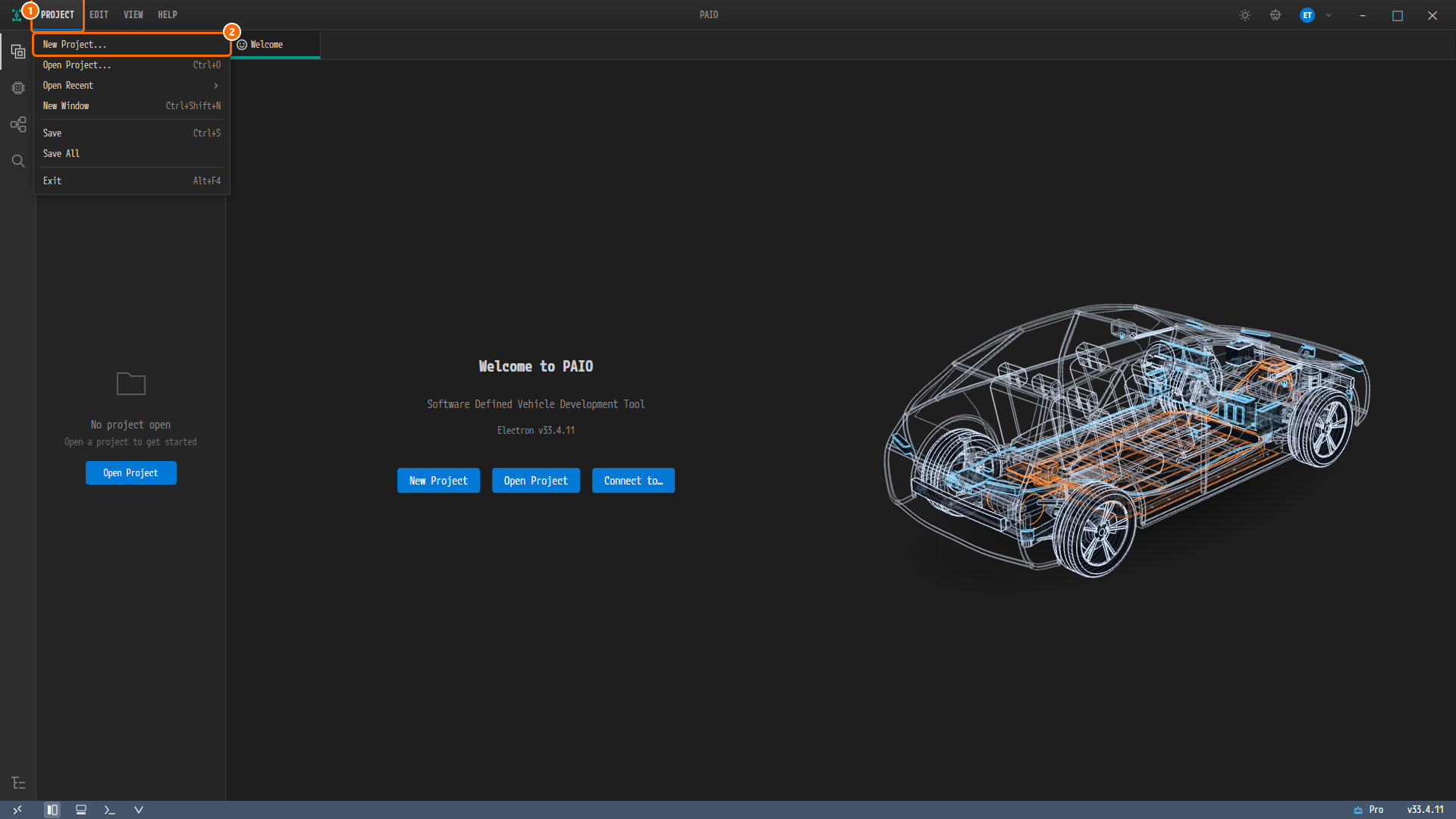
Figure 1-1. The PROJECT menu opened in a window with no project open. ① The PROJECT menu button, ② the New Project... item. The same dropdown holds Open Project..., Open Recent, New Window, Save, Save All and Exit. Behind the menu, the EDITOR view shows
No project openand the Welcome tab is open.
Entering the Name and Creating
-
In the New Project dialog, type
TopologyDesigninto Name. -
Set Location to the folder that will hold the project: type its path, or click Browse… and pick the folder. PAIO creates the project folder
TopologyDesigninside it, and the line below the fields shows that path asThe project will be created in …\TopologyDesign. Create stays disabled until both Name and Location are set. -
Click the Create button.
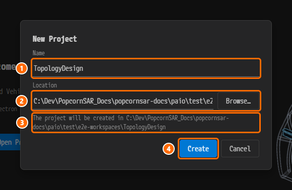
Figure 1-2. The New Project dialog. ① Name with
TopologyDesigntyped in, ② Location and the Browse… button, ③ the lineThe project will be created in …that names the new project folder, ④ the Create button. The folder in the figure is only an example; use a folder of your own.
Finding System in the EDITOR View
-
Confirm that the same window has entered the new project: the title bar reads
PAIO [TopologyDesign]and the view on the left is headedEDITOR: TopologyDesign. -
Confirm that DESIGN and MODULE are open in the EDITOR view and that System is the first row under DESIGN.
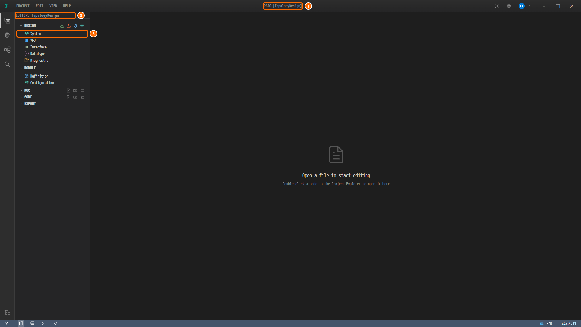
Figure 1-3. The window after Create. ① The title bar
PAIO [TopologyDesign], ② the view headerEDITOR: TopologyDesign, ③ System under DESIGN. The editor area has no tab open yet.
The items of the EDITOR view are as follows.
| Item | Role | In this tutorial |
|---|---|---|
| DESIGN › System | Editor for the vehicle network topology (nodes, controllers, connectors, clusters). The System button on the right edge of its canvas shows the system information | Most of the work, from this chapter on. Chapter 2 changes the system version |
| DESIGN › VFB, Interface, DataType, Diagnostic | Software, interface, data type and diagnostic editors | Not used |
| MODULE › Definition, Configuration | Module definitions and configuration | Not used |
| DOC | Project documents | Not used |
| CODE, EXPORT | Code and export output | EXPORT in chapter 7 |
Right after the project is created, design/ holds three files: IVC.io.model, SYSTEM.io.model, VFB.io.model. At the end of this chapter it still holds the same three files.
Creating the First ECU Node
Opening the System Editor
- In the EDITOR view on the left, click System under DESIGN. A single click opens the System editor.
- Confirm that the tab
TopologyDesign:Systemopens andSystemappears at the top left of the canvas. The canvas is empty.
Note. Creating the project alone does not open an editor. The Welcome tab closes when the window enters the project, and the editor area has no tab until you click System.
Adding an ECU to the Canvas
-
Right-click an empty spot at the top left of the canvas. The menu shows two items: Add ECU and Add HPC.
-
Click Add ECU.
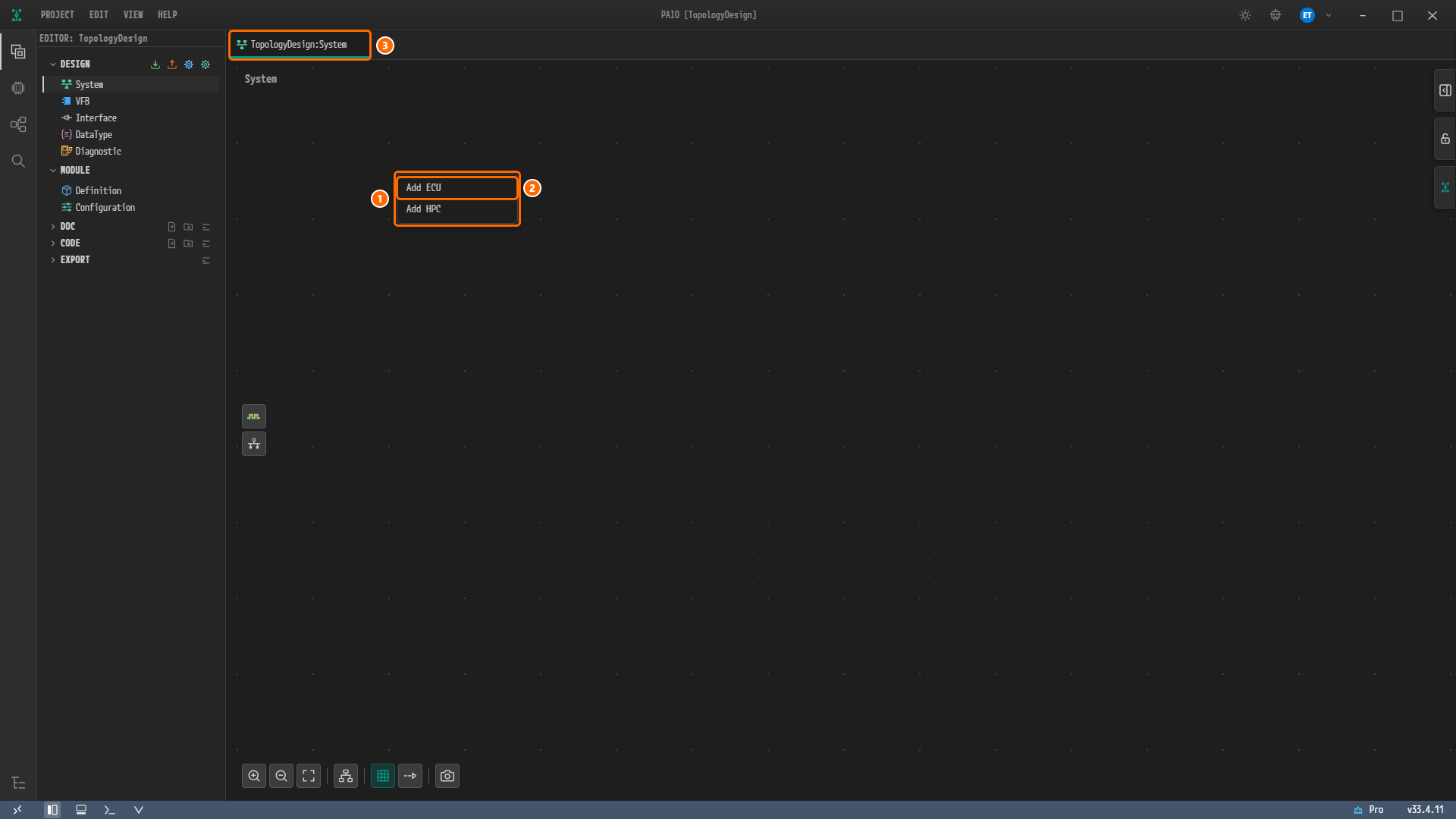
Figure 1-4. The right-click menu of the empty System editor canvas. ① The two menu items, ② Add ECU, ③ the tab
TopologyDesign:System. -
The node
ECU_0appears where you right-clicked. A blue dot (the modified mark) appears next to the tab title. -
Click the header
ECU_0of the node. A property panel titled ECU opens on the right.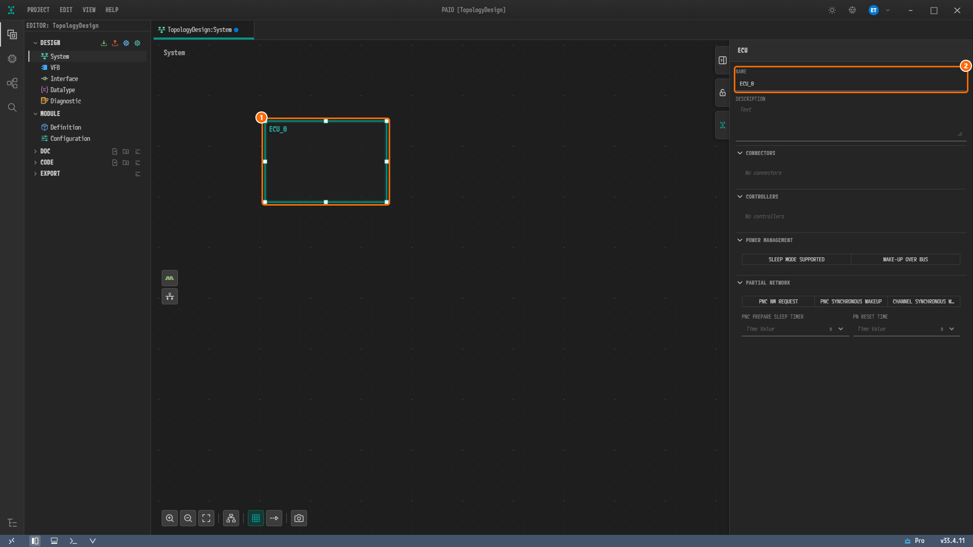
Figure 1-5. The node you just created. ① The selected node
ECU_0, ② the NAME field of the property panel. Below it are the sections DESCRIPTION, CONNECTORS (No connectors), CONTROLLERS (No controllers), POWER MANAGEMENT and PARTIAL NETWORK.
The property panel of an ECU node has the following sections. In this chapter you change only NAME.
| Section | What it shows now | In this tutorial |
|---|---|---|
| CONNECTORS | No connectors | Connectors appear in chapters 3 to 5 |
| CONTROLLERS | No controllers | Controllers appear in chapters 3 to 5 |
| POWER MANAGEMENT | Toggles SLEEP MODE SUPPORTED and WAKE-UP OVER BUS (both off) | Turned on in ECU Properties |
| PARTIAL NETWORK | Toggles such as PNC NM REQUEST and timer fields | Not used |
Renaming It to ECU
-
Delete
ECU_0in the NAME field of the property panel and typeECU. -
Press
Tab. The node header on the canvas changes toECU. The focus moves to DESCRIPTION. Leave DESCRIPTION empty.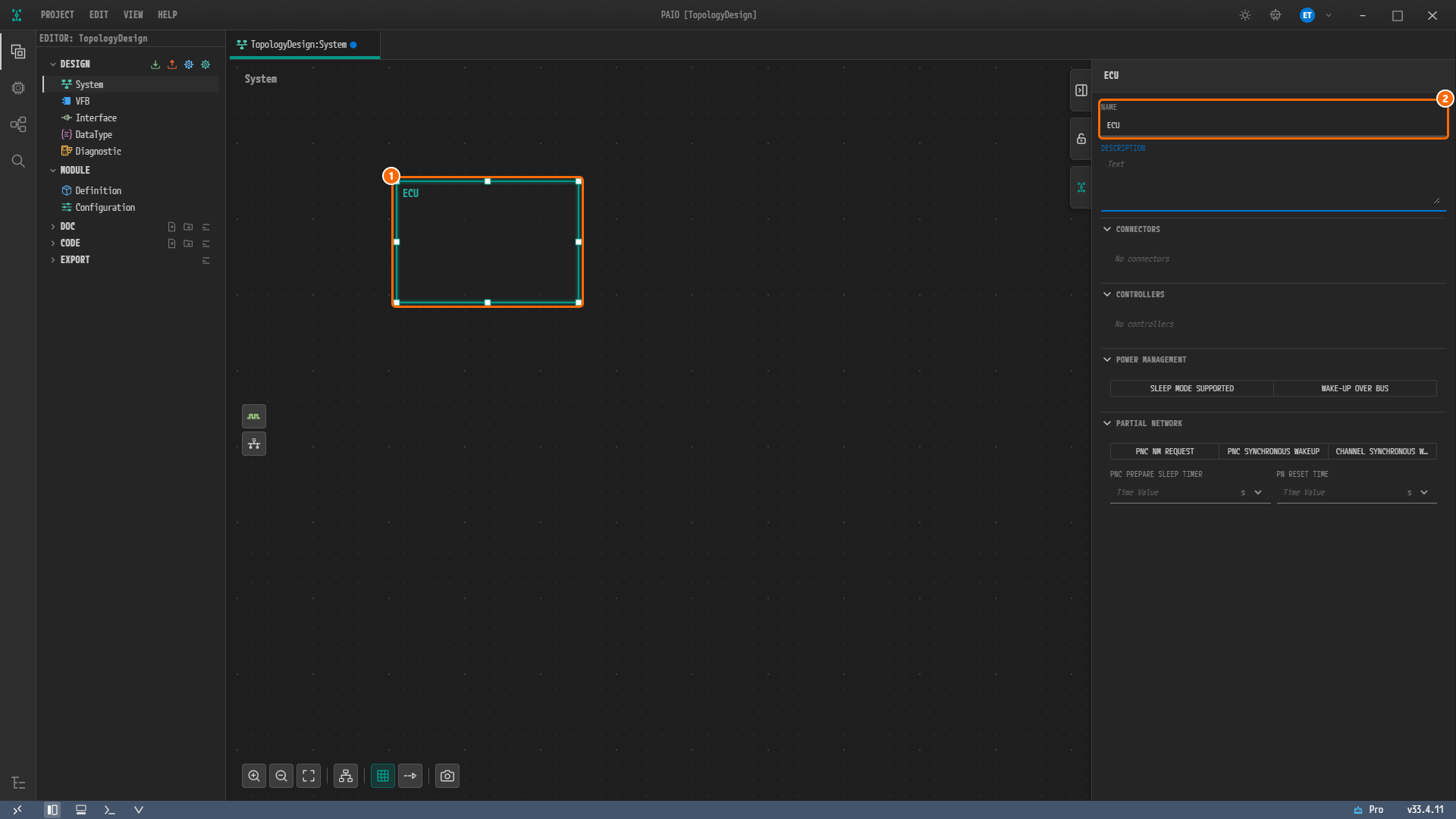
Figure 1-6. The renamed node. ① The node whose header now reads
ECU, ②ECUin the NAME field. The DESCRIPTION label, which now has the focus, shows in blue.
Creating the Remaining Nodes
Making the Second ECU into ZONE
-
Right-click an empty spot at the top right of the canvas and click Add ECU.
-
Confirm that the new node is named
ECU_0again. Because you renamed the previous node, the same default name is used again.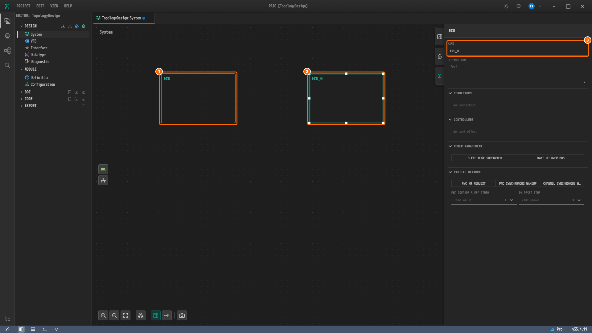
Figure 1-7. The second ECU node. ①
ECU, created earlier, ② the new nodeECU_0, ③ECU_0in the NAME field. -
With the new node selected, type
ZONEinto the NAME field and pressTab.
Adding the Third ECU and the HPC
-
Right-click an empty spot at the bottom left of the canvas and click Add ECU. Type
SLAVE_ECUinto the NAME of the new nodeECU_0and pressTab. -
Right-click an empty spot at the bottom right of the canvas and this time click Add HPC.
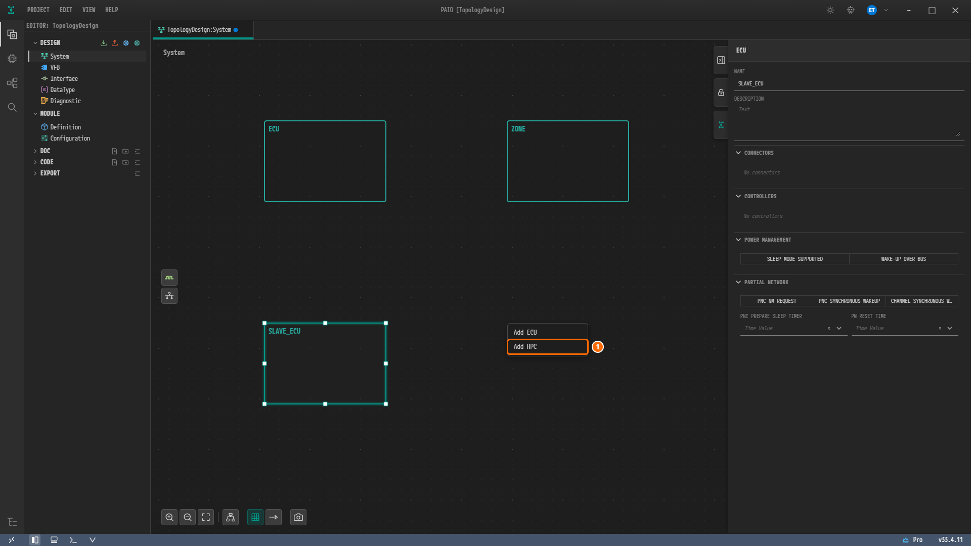
Figure 1-8. The menu opened at the bottom right after three nodes exist. ① Add HPC.
ECUandZONEare at the top, and the selectedSLAVE_ECUis at the bottom left. -
The node
HPC_0appears. Click its header and a property panel titled HPC opens.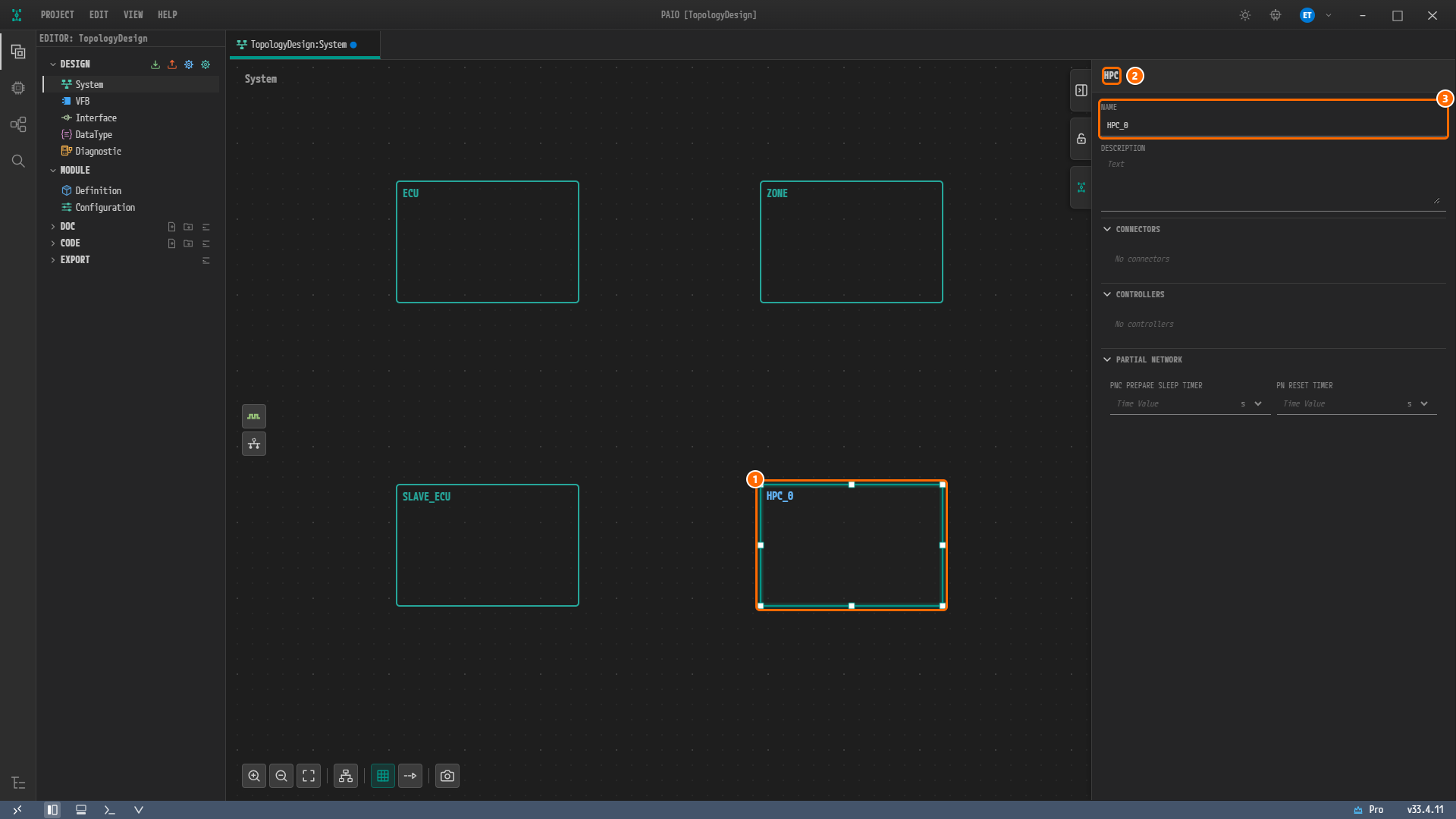
Figure 1-9. The HPC node you just created. ① The node
HPC_0, ② the panel title HPC, ③HPC_0in the NAME field. Unlike the ECU panel, it has no POWER MANAGEMENT section. -
Type
HPCinto the NAME field and pressTab.
The values for the four nodes are collected below. Always add them in the order of the table.
| Order | Right-click position | Menu item | Node created | Type into NAME |
|---|---|---|---|---|
| 1 | Top left of the canvas | Add ECU | ECU_0 | ECU |
| 2 | Top right of the canvas | Add ECU | ECU_0 | ZONE |
| 3 | Bottom left of the canvas | Add ECU | ECU_0 | SLAVE_ECU |
| 4 | Bottom right of the canvas | Add HPC | HPC_0 | HPC |
Caution. Keep the order
ECU→ZONE→SLAVE_ECU→HPC. The order fixes no name: each node is saved under the name you type into NAME, and the default namesECU_0andHPC_0do not remain in the project once you rename the nodes. The ECU nodes are, however, saved and exported in the order you add them, so the line numbers quoted in ARXML Export match only in the order of the table.
Saving
-
Click the empty canvas between the four nodes. The selection clears and the property panel collapses.
-
Press
Ctrl+Sto save. The blue dot on the tab title disappears.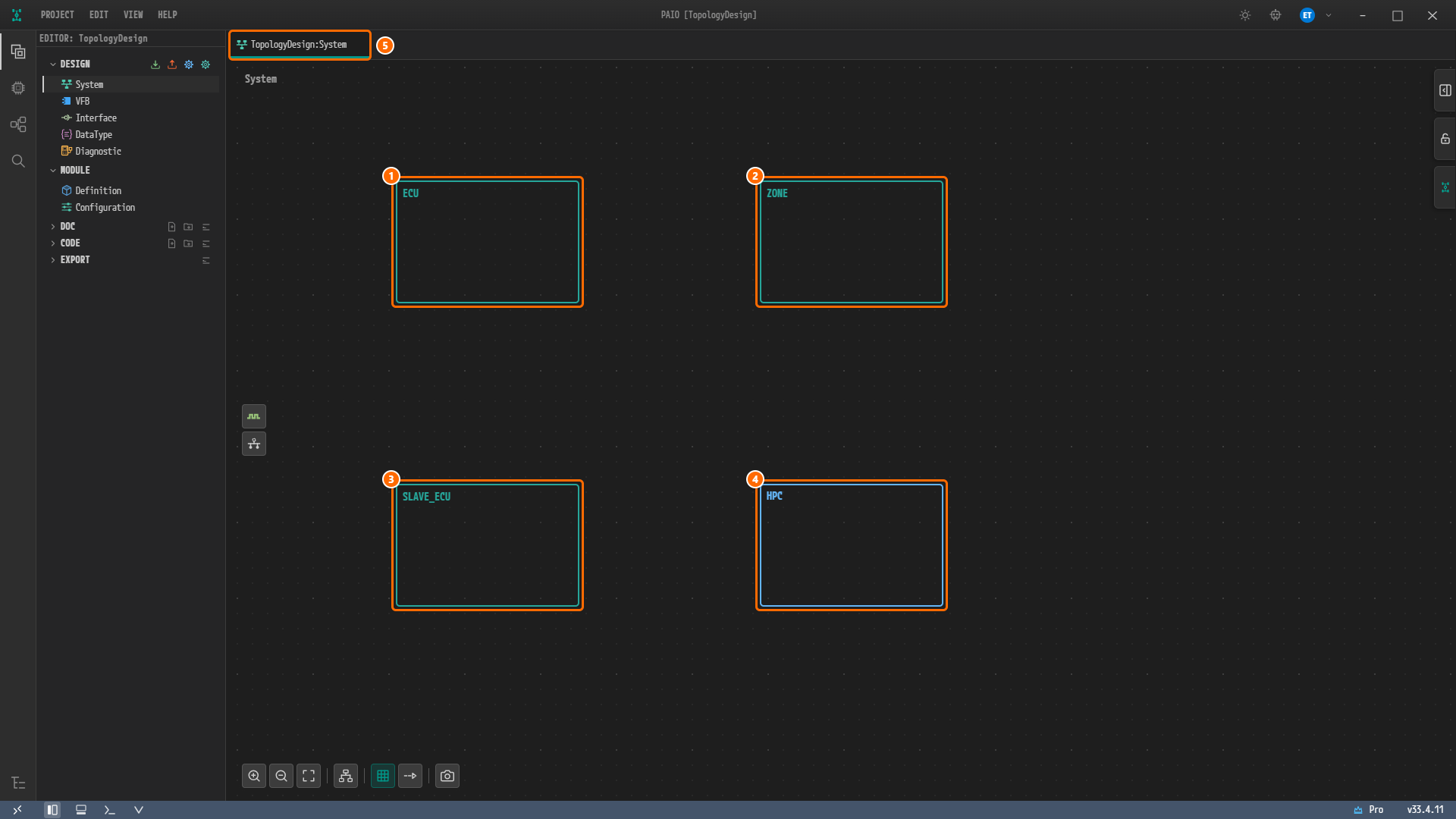
Figure 1-10. The System editor after saving. ①
ECU, ②ZONE, ③SLAVE_ECU, ④HPC, ⑤ the tabTopologyDesign:Systemwithout the modified mark. The ECU nodes have a teal border, the HPC node a blue one.
Note. To clear the selection, click the middle of the canvas where there is no node. Clicking the edge of the canvas, especially near the bottom toolbar, can leave the selection as it is.
Viewing the Validation Result
-
Click the V icon (tooltip
Toggle Validation) in the footer at the bottom of the window to open the VALIDATION panel. When the panel opens, the canvas shrinks upward.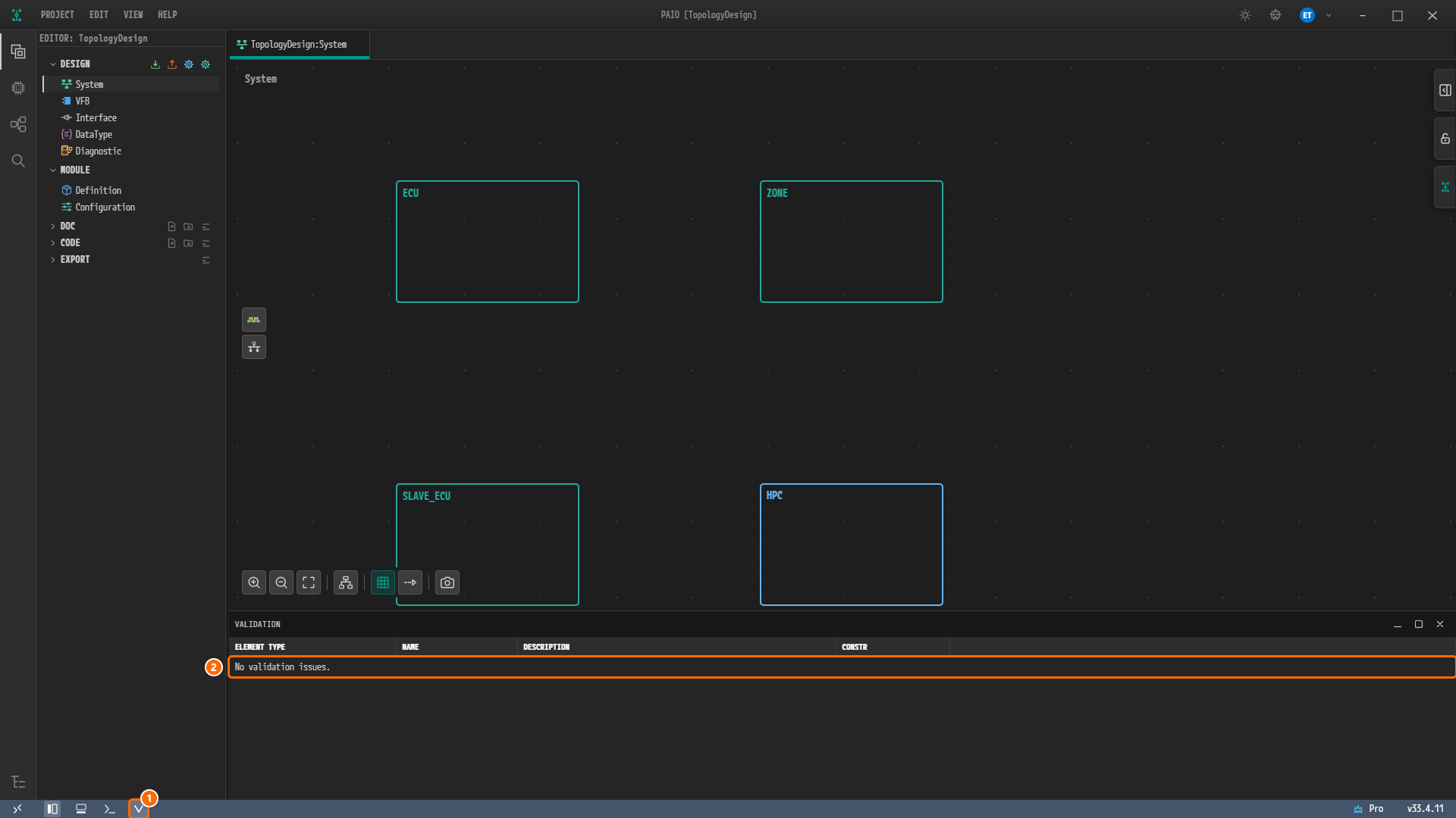
Figure 1-11. The VALIDATION panel. ① The V icon in the footer, ② the row
No validation issues.. The columns are ELEMENT TYPE / NAME / DESCRIPTION / CONSTR.
The validation result is zero findings (0 errors, 0 warnings). This result is expected.
Note. Validation checks the project open in the window. There is no project row to select first.
Why Is It Designed This Way?
- The names carry the roles of the four nodes.
ECUis the ECU with both CAN and a LIN master,ZONEis the ECU with both CAN and Ethernet,SLAVE_ECUis the LIN slave ECU, andHPCis the HPC node connected only to Ethernet. Later chapters tell the nodes apart by these names when they add the buses. - Only
HPCis created as an HPC node. An HPC node is stored as a different element (a machine design) from an ECU node, and its property panel has no POWER MANAGEMENT section. That is why the next chapter turns on the power management settings only on the three ECU nodes. - The nodes are placed in a 2x2 grid without Auto Layout. A node appears where you right-click, so choosing the positions yourself lets you follow later chapters with the same screen as their figures.
Checklist
- The title bar reads
PAIO [TopologyDesign], and System, VFB, Interface, DataType, Diagnostic are listed under DESIGN in the EDITOR view. - The System editor (tab
TopologyDesign:System) holds the nodesECU,ZONE,SLAVE_ECU,HPCin a 2x2 grid. -
ECU,ZONE,SLAVE_ECUhave a teal border andHPCa blue one. - Selecting
HPCshows the panel title HPC; selecting any of the other three shows ECU. - The tab
TopologyDesign:Systemcarries no modified mark. -
design/in the project folder holds three files:IVC.io.model,SYSTEM.io.model,VFB.io.model. - The VALIDATION panel shows
No validation issues..
Next Step
In ECU Properties you change the system version and turn on the POWER MANAGEMENT toggles of the three ECU nodes.