Ethernet Bus
What You Will Do
In this chapter you join the nodes ZONE and HPC with an Ethernet bus, in the System editor as you left it in CAN Bus.
You create one Ethernet controller (EthernetCommController, EthernetController) and one Ethernet connector (EthernetConnector) on each of the two nodes and enter IPv4 addresses on the connectors. You then create the Ethernet cluster EthernetCluster from the + badge of a connector and connect both connectors to the physical channel PhysicalChannel, whose VLAN ID is 13.
Network management (NM) is off for a new cluster and is turned on per cluster in the Communication Cluster Configuration window. The reference design has no NM, so you only check in that window that it is off.
When you finish this chapter, the design in which EthernetCluster joins ZONE and HPC is saved in the System editor, and the VALIDATION panel shows No validation issues..
Before You Begin
- Start after finishing CAN Bus.
ECUandZONEhave CAN controllers and connectors and are joined byCanCluster, whileSLAVE_ECUandHPCare still empty. The VALIDATION panel showsNo validation issues.. - If the tab
TopologyDesign:Systemis not open, click System under DESIGN in the EDITOR view. - If the VALIDATION panel is open, close it with the V icon in the footer. The figures show the screen with the panel closed.
- When you select an element, the property panel opens on the right and covers the right side of the canvas. If the node
HPCis hidden under the panel, click Fit to View in the toolbar below the canvas and then click Zoom Out a few times until all four nodes are visible. The figures in this chapter show the canvas zoomed out this way.
The values you enter in this chapter are listed below. The channel name PhysicalChannel is a default that is filled in automatically when the cluster is created, so you do not type it.
| Where | Item | Value |
|---|---|---|
ETHERNET CONTROLLER panel (node ZONE) | NAME / MAC ADDRESS | EthernetCommController / 11:22:EE:44:55:66 |
ETHERNET CONTROLLER panel (node HPC) | NAME / MAC ADDRESS | EthernetController / 00:11:22:33:44:55 |
ETHERNET CONNECTOR panel (node ZONE) | NAME / CONTROLLER | EthernetConnector / select EthernetCommController |
ETHERNET CONNECTOR panel (node ZONE) | UNICAST IPV4 ADDRESS / ADDRESS SOURCE | 192.168.0.19 / click FIXED |
ETHERNET CONNECTOR panel (node HPC) | NAME / CONTROLLER | EthernetConnector / select EthernetController |
ETHERNET CONNECTOR panel (node HPC) | UNICAST IPV4 ADDRESS / ADDRESS SOURCE | 192.168.0.11 / click FIXED |
ETHERNET CONNECTOR panel (node HPC) | MULTICAST IPV4 ADDRESS | 224.0.0.1 |
| ETHERNET CLUSTER panel | NAME / VLAN ID | EthernetCluster / 13 |
| ETHERNET CLUSTER panel | PHYSICAL CHANNELS › CHANNEL NAME | PhysicalChannel (default, leave as is) |
| Communication Cluster Configuration window | NM CLUSTER, TIME DOMAIN tabs | Disabled (default, leave as is) |
Note. A field in the property panel commits its value only when you leave the field. In this chapter you press the
Tabkey after entering a value in the property panel.
Creating the Ethernet Controllers
Adding a Controller
-
On the canvas, right-click an empty spot inside the node
ZONE. The menu shows Add Connector, Add Controller, Add Ethernet Switch, Add Gateway, SW Mapping, Extract ECU and Delete. -
Hover over Add Controller and click Ethernet in the submenu.
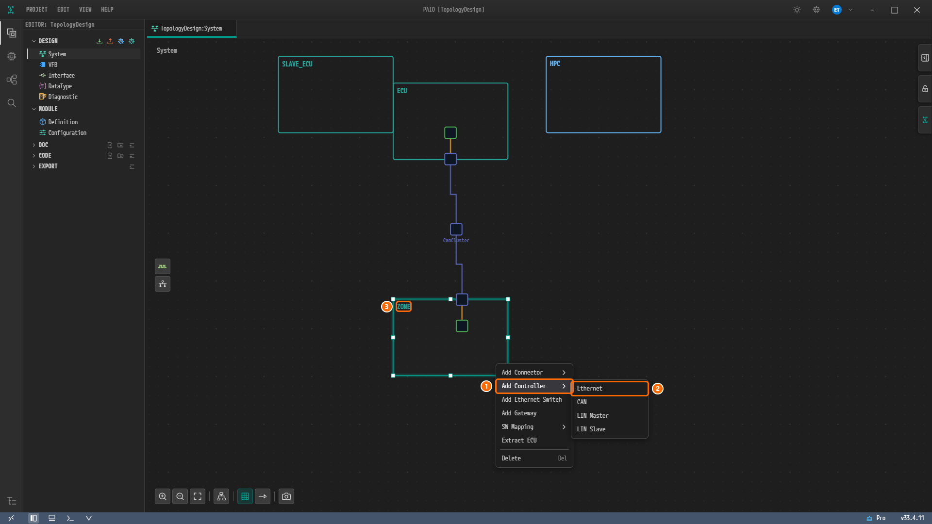
Figure 4-1. The context menu of the node
ZONE. ① Add Controller, ② Ethernet in the submenu, ③ the right-clicked nodeZONE. The submenu of Add Controller holds Ethernet, CAN, LIN Master and LIN Slave. -
A small square appears inside the node. This is the Ethernet controller. The new controller is not selected automatically, so click the square. The property panel on the right is titled ETHERNET CONTROLLER, and NAME holds the default name
ZONE_Ethernet_Controller_0.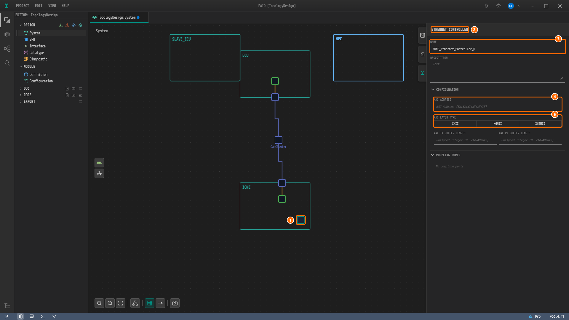
Figure 4-2. The new Ethernet controller. ① The controller inside the node, ② the panel title ETHERNET CONTROLLER, ③ NAME =
ZONE_Ethernet_Controller_0, ④ the empty MAC ADDRESS, ⑤ MAC LAYER TYPE with all three values off.
The CONFIGURATION section of the ETHERNET CONTROLLER panel holds MAC ADDRESS, MAC LAYER TYPE, MAX TX BUFFER LENGTH and MAX RX BUFFER LENGTH, and the COUPLING PORTS section below it shows No coupling ports. This chapter uses only NAME and MAC ADDRESS.
Entering the Name and MAC Address
-
In the NAME field, delete
ZONE_Ethernet_Controller_0, typeEthernetCommControllerand press theTabkey. -
Type
11:22:EE:44:55:66into MAC ADDRESS and press theTabkey. An empty field shows the hintMAC Address (XX:XX:XX:XX:XX:XX). The value you typed is immediately shown in lowercase as11:22:ee:44:55:66. -
Do not click XMII, XGMII or XXGMII of MAC LAYER TYPE.
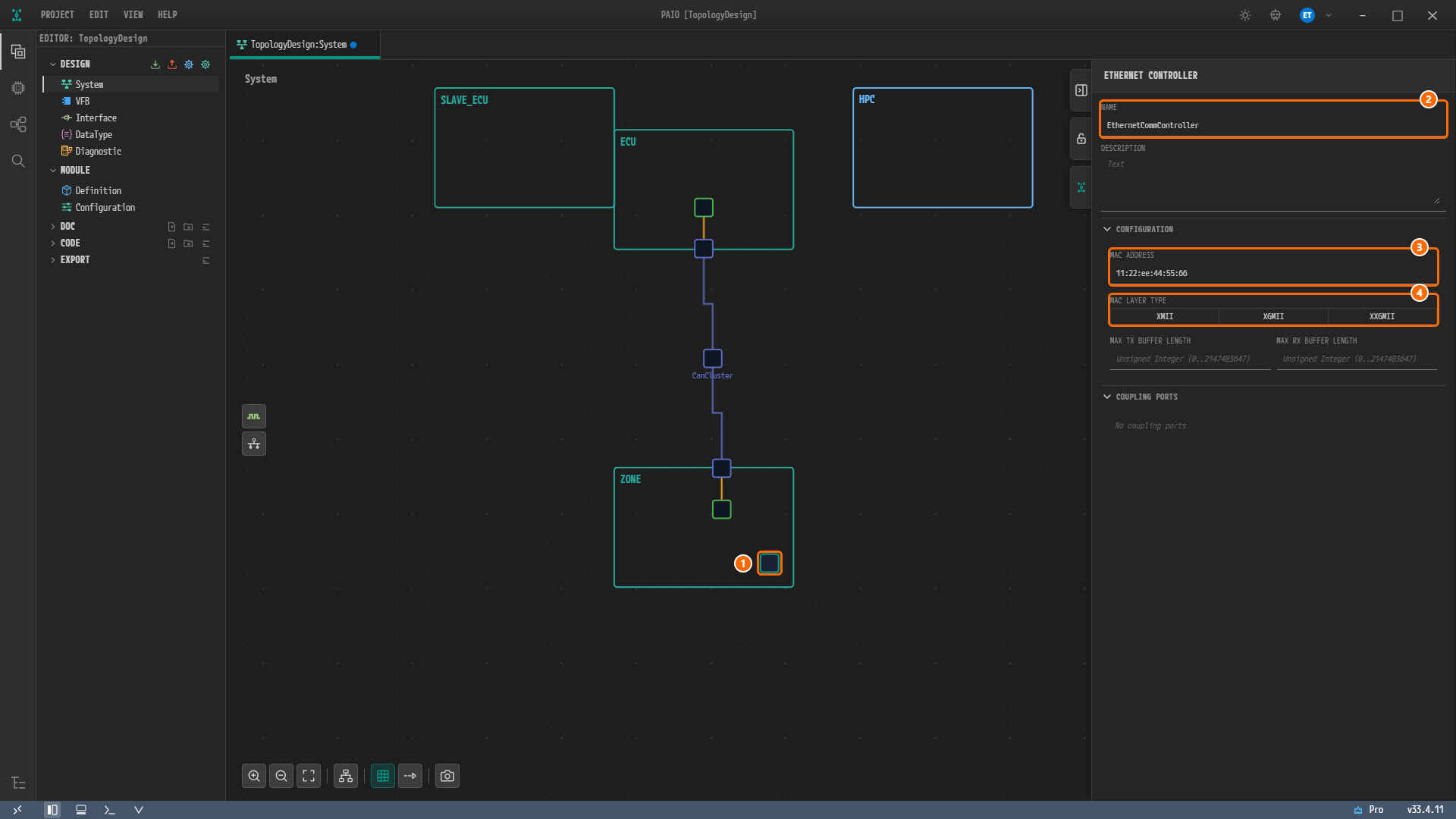
Figure 4-3. After entering the values. ① The controller, ② NAME =
EthernetCommController, ③ MAC ADDRESS shown in lowercase as11:22:ee:44:55:66, ④ MAC LAYER TYPE, left unclicked.
Note. MAC ADDRESS is saved in lowercase even when you type it in uppercase, and no warning appears. It differs from the reference design value
11:22:EE:44:55:66only in letter case and is the same address.
Caution. Do not click MAC LAYER TYPE. The two Ethernet controllers of the reference design have the MAC layer type
X-MII, but the values of this toggle areXMII,XGMIIandXXGMII. Clicking XMII putsXMIIinto the exported ARXML as is. The AUTOSAR schema (XSD) allows onlyX-MII,XG-MIIandXXG-MII, soXMIIis not a schema value, and the XML editor's schema check reports it as an error when you open the exported file. If you leave the toggle alone, the export result has no MAC layer type. This difference is covered in ARXML Export.
Creating a Controller on HPC
-
Right-click an empty spot inside the node
HPC. The menu is the same as forZONE, except that the item just above Delete is Extract Machine instead of Extract ECU. -
Click Add Controller › Ethernet.
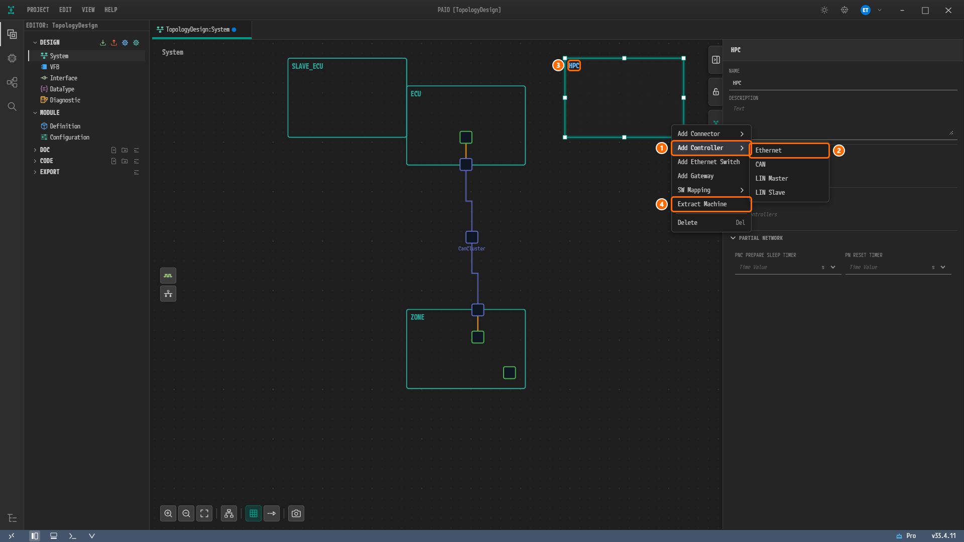
Figure 4-4. The context menu of the node
HPC. ① Add Controller, ② Ethernet in the submenu, ③ the right-clicked nodeHPC, ④ Extract Machine. Right-clicking selects the nodeHPC, so the panel now shows the HPC panel with NAMEHPC. -
A controller square appears inside
HPC. Click it; the ETHERNET CONTROLLER panel shows NAMEHPC_Ethernet_Controller_0. TypeEthernetControllerinto NAME and press theTabkey. -
Type
00:11:22:33:44:55into MAC ADDRESS and press theTabkey. Again, do not click MAC LAYER TYPE.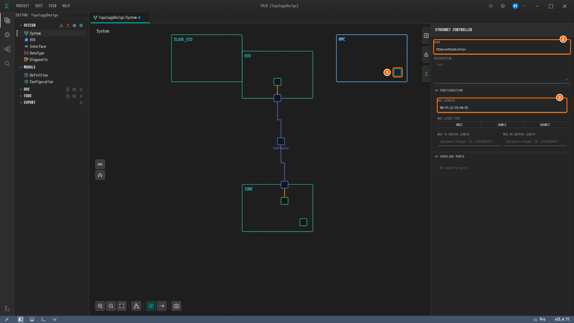
Figure 4-5. The Ethernet controller of the node
HPC. ① The controller insideHPC, ② NAME =EthernetController, ③ MAC ADDRESS =00:11:22:33:44:55.
The values of the two controllers are collected below.
| Node | Default name | NAME | MAC ADDRESS | MAC LAYER TYPE |
|---|---|---|---|---|
ZONE | ZONE_Ethernet_Controller_0 | EthernetCommController | Type 11:22:EE:44:55:66 (saved as 11:22:ee:44:55:66) | Do not click |
HPC | HPC_Ethernet_Controller_0 | EthernetController | 00:11:22:33:44:55 | Do not click |
Creating the Ethernet Connectors
Adding a Connector
-
Right-click an empty spot inside the node
ZONE. -
Hover over Add Connector and click Ethernet in the submenu. The submenu holds Ethernet, CAN and LIN.
-
A connector square appears on the bottom edge of the node
ZONE, with a green + badge below it. The connector is not selected automatically either, so click the connector square. The panel is titled ETHERNET CONNECTOR; NAME isZONE_Ethernet_Connector_0, CONTROLLER isSelect controller...and CONNECTED CHANNEL is(None). CONTROLLER is a required field: while it is empty, its label is red with the hintController is required, and the V icon in the footer shows the red badge1.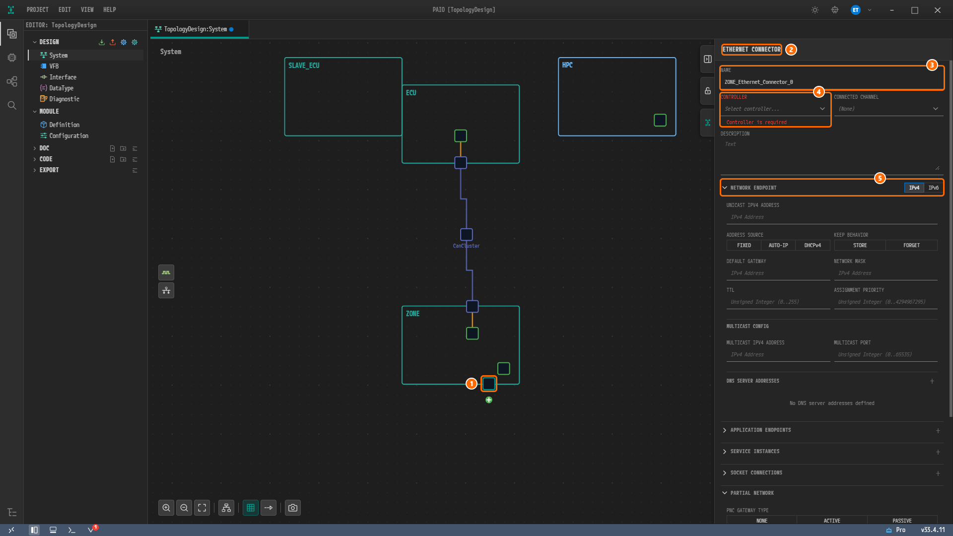
Figure 4-6. The new Ethernet connector. ① The connector on the bottom edge of the node, ② the panel title ETHERNET CONNECTOR, ③ NAME =
ZONE_Ethernet_Connector_0, ④ CONTROLLER =Select controller..., red withController is required, ⑤ the NETWORK ENDPOINT header with IPv4 on. All endpoint fields are empty, all three values of ADDRESS SOURCE are off, and the V icon in the footer shows the badge1.
The NETWORK ENDPOINT section holds UNICAST IPV4 ADDRESS, ADDRESS SOURCE (FIXED, AUTO-IP, DHCPv4), KEEP BEHAVIOR, DEFAULT GATEWAY, NETWORK MASK, TTL, ASSIGNMENT PRIORITY, MULTICAST IPV4 ADDRESS and MULTICAST PORT under the subheading MULTICAST CONFIG, and DNS SERVER ADDRESSES. Below it follow APPLICATION ENDPOINTS, SERVICE INSTANCES, SOCKET CONNECTIONS, PARTIAL NETWORK, TX PDUS and RX PDUS. This chapter uses only NAME, CONTROLLER, UNICAST IPV4 ADDRESS, ADDRESS SOURCE and MULTICAST IPV4 ADDRESS.
Setting the Name, Controller and Address
-
Type
EthernetConnectorinto NAME and press theTabkey. -
Click the CONTROLLER field and click
EthernetCommControllerin the list. The list holds only one item,EthernetCommController, the Ethernet controller of the same node. An orange line joining the connector and the controller appears on the canvas. The red mark of CONTROLLER and the badge on the V icon disappear. -
Type
192.168.0.19into UNICAST IPV4 ADDRESS and press theTabkey. An empty field shows the hintIPv4 Address. -
Click FIXED of ADDRESS SOURCE.
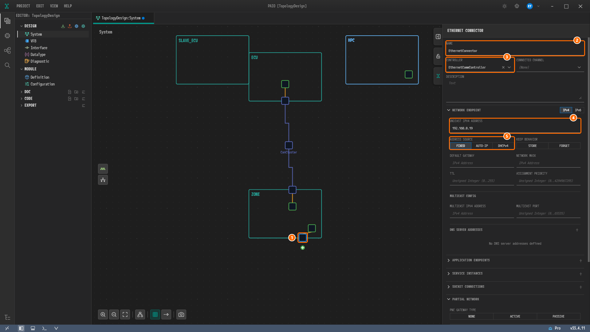
Figure 4-7. After entering the values. ① The connector, ② NAME =
EthernetConnector, ③ CONTROLLER =EthernetCommController, ④ UNICAST IPV4 ADDRESS =192.168.0.19, ⑤ ADDRESS SOURCE with FIXED on.
Caution. All three values of ADDRESS SOURCE are off at first. If you do not click FIXED, the connector is saved with no address source.
Creating a Connector on HPC
-
Right-click an empty spot inside the node
HPCand click Add Connector › Ethernet. A connector square appears on the bottom edge ofHPC. Click it; the ETHERNET CONNECTOR panel shows NAMEHPC_Ethernet_Connector_0. -
Type
EthernetConnectorinto NAME and press theTabkey. -
Click
EthernetControllerin the CONTROLLER list. It is the only item in the list. -
Type
192.168.0.11into UNICAST IPV4 ADDRESS, press theTabkey, and click FIXED of ADDRESS SOURCE. -
Type
224.0.0.1into MULTICAST IPV4 ADDRESS under MULTICAST CONFIG and press theTabkey. Leave MULTICAST PORT empty.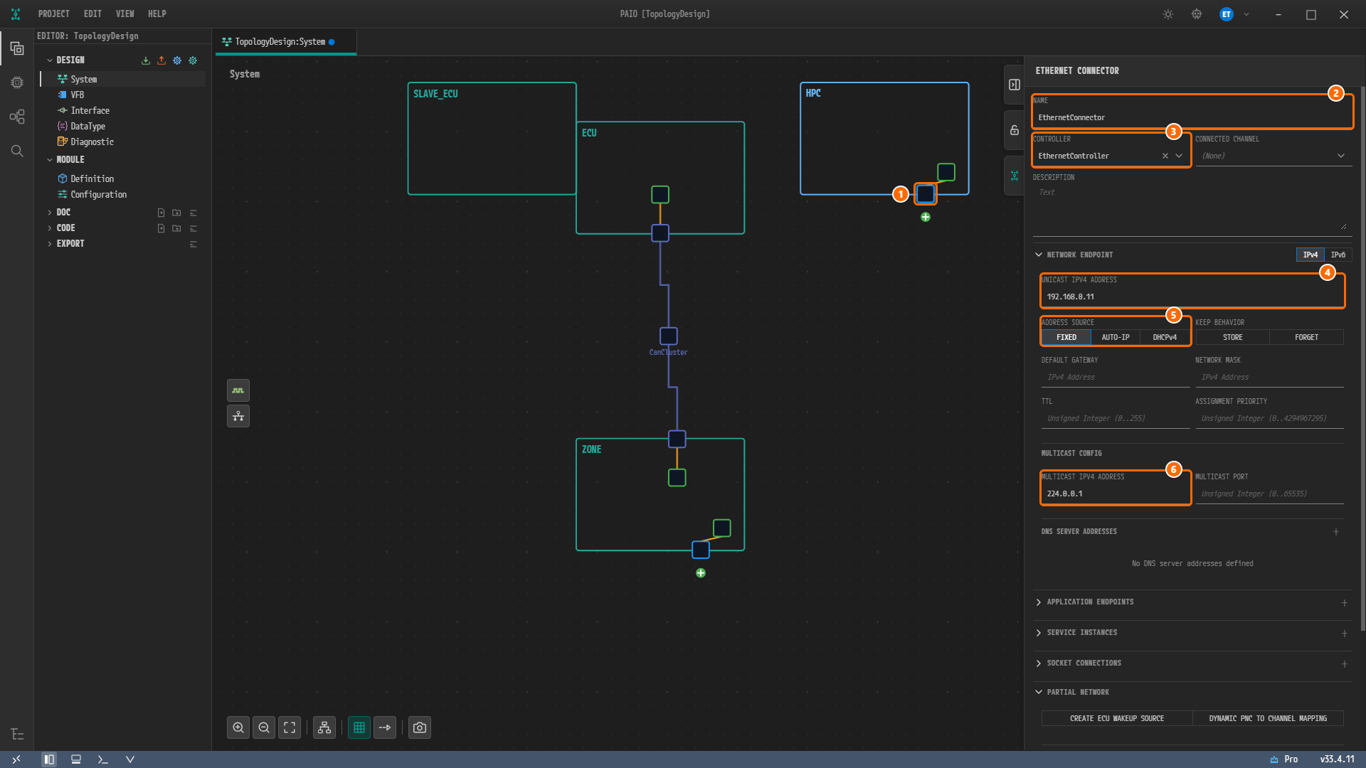
Figure 4-8. The Ethernet connector of the node
HPC. ① The connector ofHPC, ② NAME =EthernetConnector, ③ CONTROLLER =EthernetController, ④ UNICAST IPV4 ADDRESS =192.168.0.11, ⑤ ADDRESS SOURCE with FIXED on, ⑥ MULTICAST IPV4 ADDRESS =224.0.0.1.
The values of the two connectors are collected below.
| Node | Default name | NAME | CONTROLLER | UNICAST IPV4 ADDRESS | ADDRESS SOURCE | MULTICAST IPV4 ADDRESS |
|---|---|---|---|---|---|---|
ZONE | ZONE_Ethernet_Connector_0 | EthernetConnector | EthernetCommController | 192.168.0.19 | FIXED | Leave empty |
HPC | HPC_Ethernet_Connector_0 | EthernetConnector | EthernetController | 192.168.0.11 | FIXED | 224.0.0.1 |
Note. In the reference design, the connector
EthernetConnectorofHPChas no controller assigned, and its unicast address points to the endpoint ofZONE(192.168.0.19). This tutorial corrects that and builds the connector with the own controller ofHPC,EthernetController, and the address192.168.0.11. The difference is covered in detail in ARXML Export.
Endpoints and Connector Addresses
The reference design places three network endpoints under the Ethernet channel, and the connectors point to these endpoints. The System editor has no field for creating an endpoint separately and no field for an endpoint name; you enter an endpoint through the address fields of a connector. The addresses you entered above correspond as follows.
| Endpoint of the reference design | Address | Where you entered it in this chapter |
|---|---|---|
ZONE_Endpoint | 192.168.0.19 (FIXED) | UNICAST IPV4 ADDRESS and ADDRESS SOURCE of the ZONE connector |
HPC_Endpoint | 192.168.0.11 (FIXED) | UNICAST IPV4 ADDRESS and ADDRESS SOURCE of the HPC connector |
SOMEIP_SD_Multicast | 224.0.0.1 | MULTICAST IPV4 ADDRESS of the HPC connector |
SOMEIP_SD_Multicast is the multicast address used for SOME/IP service discovery (SD), and you enter it only on the HPC connector. On export, PAIO names the endpoints after the node and connector names (for example HPC_EthernetConnector_Endpoint), so the names differ from those of the reference design.
Creating the Ethernet Cluster
Creating the Cluster from the ZONE Connector
The connector from which you create the cluster becomes the first connector of the channel. To match the order of the reference design (ZONE, HPC), you create the cluster from the connector of ZONE.
-
Click the green + badge below
EthernetConnectorof the nodeZONE. -
Click Create CommunicationCluster [Ethernet] in the menu that opens. It is the only item in the menu.
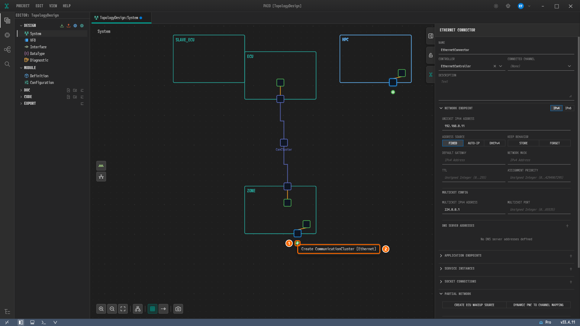
Figure 4-9. The + badge menu of the
ZONEconnector. ① The + badge, ② Create CommunicationCluster [Ethernet]. The panel still shows the connector ofHPCedited before. -
A cluster square appears below
ZONE, with its nameEthernetCluster_0written under it. If you cannot see it, click Fit to View, and ifHPCis hidden under the panel, click Zoom Out. -
Click the cluster square. The panel is titled ETHERNET CLUSTER, and NAME is
EthernetCluster_0.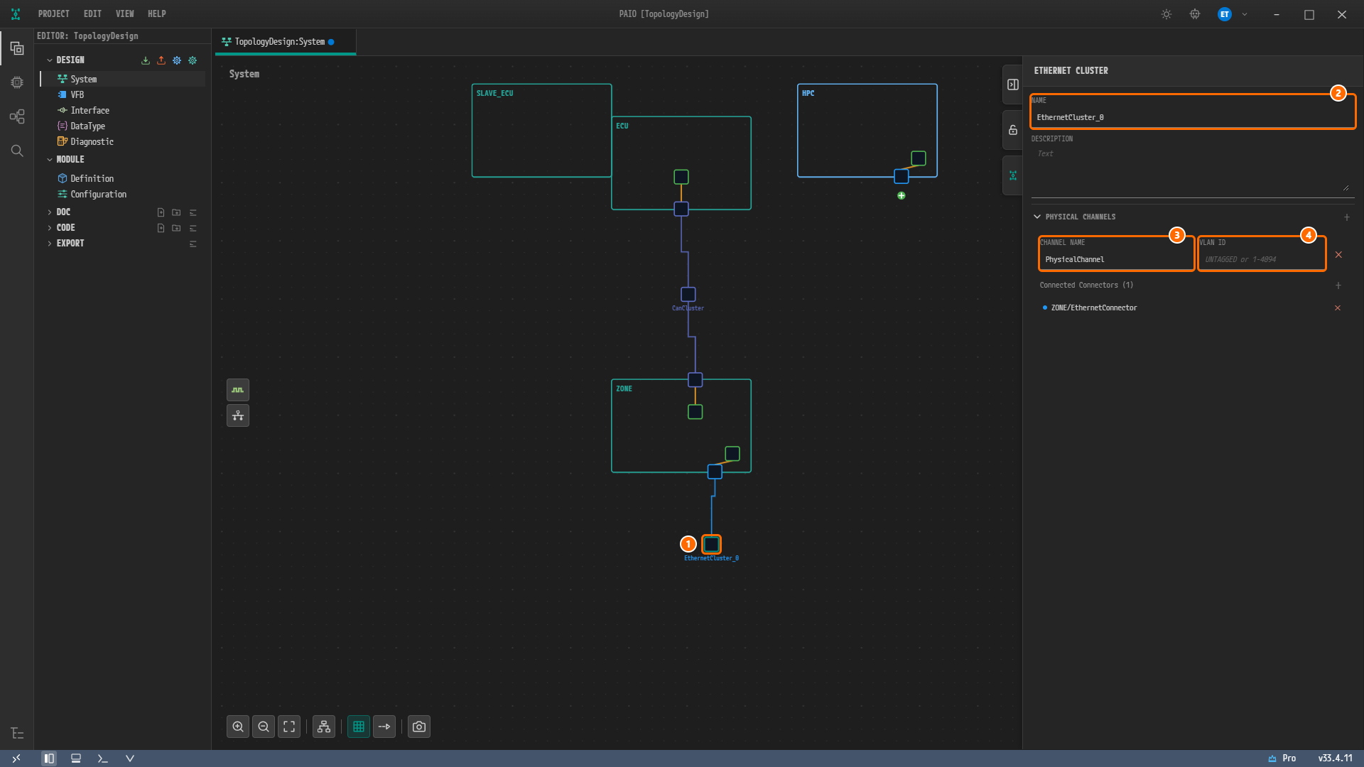
Figure 4-10. The new Ethernet cluster. ① The cluster square, ② NAME =
EthernetCluster_0, ③ CHANNEL NAME holding the defaultPhysicalChannel, ④ the empty VLAN ID showing the hintUNTAGGED or 1-4094.ZONE/EthernetConnectoris listed under Connected Connectors (1). -
Type
EthernetClusterinto NAME and press theTabkey. The name under the square changes toEthernetCluster. -
Type
13into VLAN ID and press theTabkey. Leave CHANNEL NAME as it is.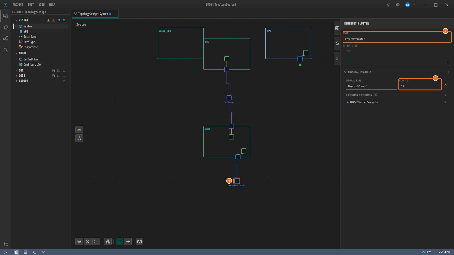
Figure 4-11. After entering the values. ① The cluster square, ② NAME =
EthernetCluster, ③ VLAN ID =13.
Note. Unlike the CAN CLUSTER panel, the ETHERNET CLUSTER panel has no PROTOCOL section. There are no fields for a baud rate or a protocol name, and the VLAN is set only through the VLAN ID of the channel.
Connecting the HPC Connector to the Channel
-
Click the green + badge below
EthernetConnectorof the nodeHPC. This time the menu holds Create CommunicationCluster [Ethernet] and Connect to Channel.... -
Hover over Connect to Channel..., hover over EthernetCluster in its submenu, and click PhysicalChannel (VLAN: 13) in the next submenu. The VLAN ID is shown next to the channel name.
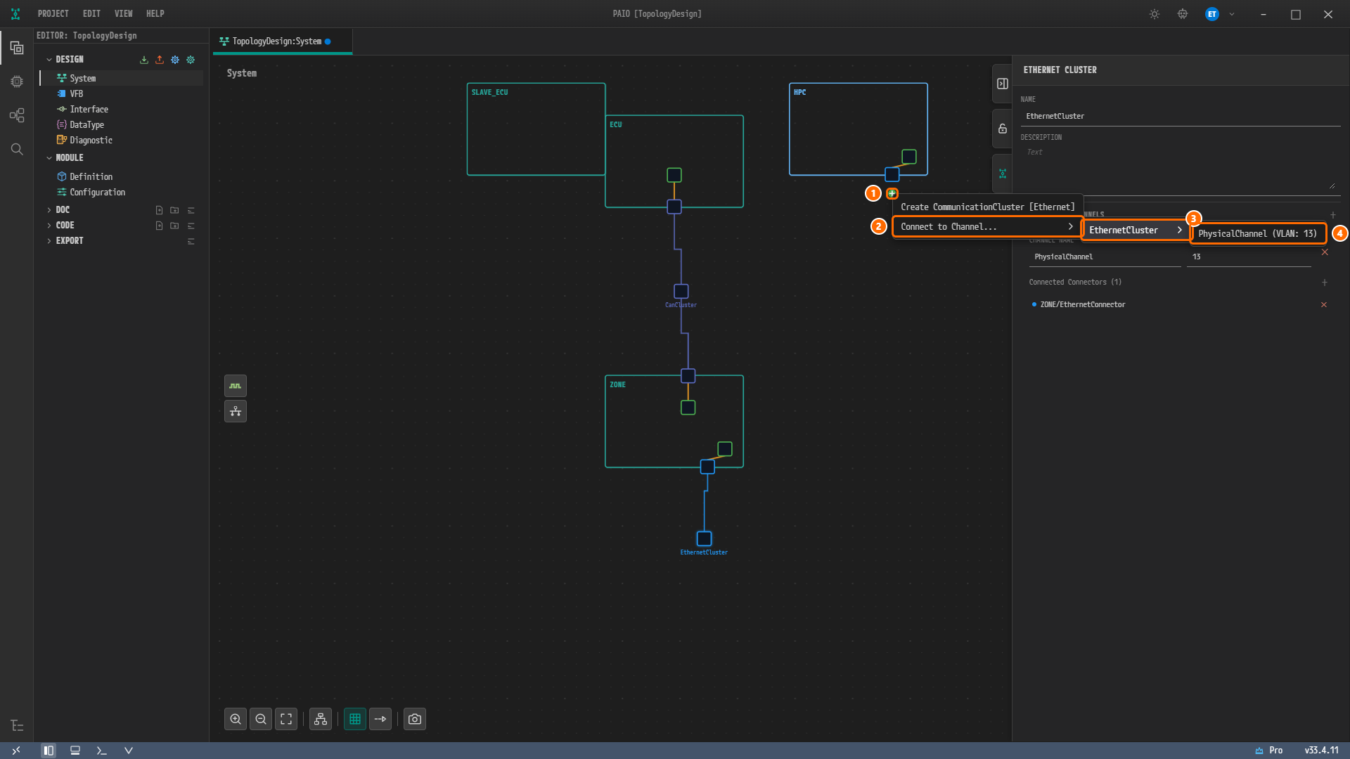
Figure 4-12. The + badge menu of the
HPCconnector. ① The + badge, ② Connect to Channel..., ③ EthernetCluster, ④ PhysicalChannel (VLAN: 13).
Note. The + badge of the
HPCconnector is smaller than the one on theZONEside. If it is hard to click, zoom in before clicking it. Also, when the connector is close to the right edge of the screen, the third menu may open to the left and cover the earlier menus. In that case, close the menu, click Zoom Out once more, and open it again.
Caution. Create CommunicationCluster [Ethernet] in this menu creates a new cluster. Connect the connector of
HPCto the channel created earlier with Connect to Channel....
Tidying the Layout and Saving
-
Click Auto Layout in the toolbar below the canvas, then click Fit to View. If
HPCis hidden under the panel, click Zoom Out. -
Click the Ethernet cluster square and confirm that VLAN ID is
13and thatZONE/EthernetConnectorandHPC/EthernetConnectorare listed under Connected Connectors (2).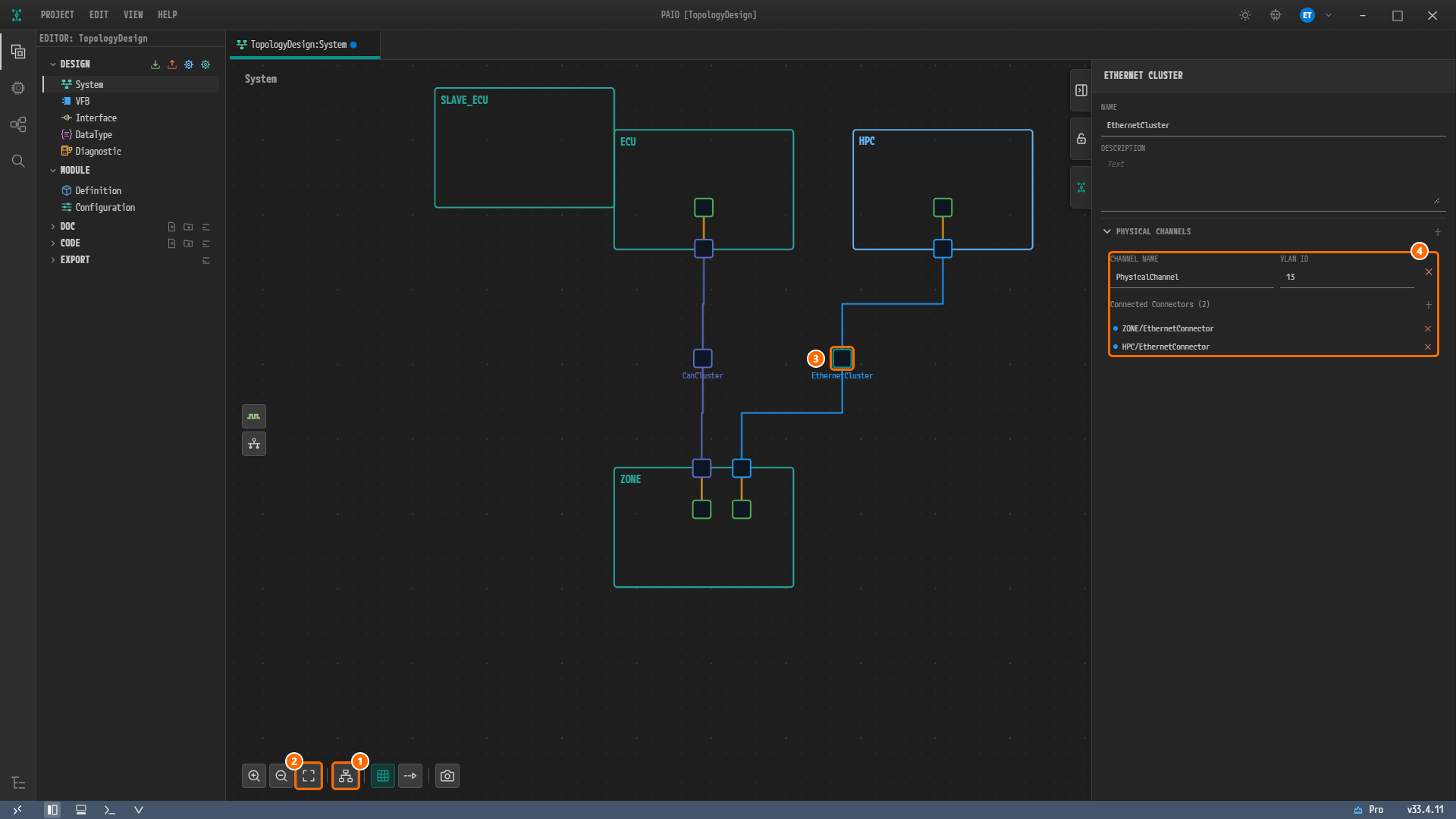
Figure 4-13. The canvas after Auto Layout. ① Auto Layout, ② Fit to View, ③ the Ethernet cluster square, ④ CHANNEL NAME
PhysicalChannel, VLAN ID13andZONE/EthernetConnector,HPC/EthernetConnectorunder Connected Connectors (2). The Ethernet cluster sits betweenHPCandZONE, withCanClusterto its left. -
Click the empty canvas where there is no node, then press
Ctrl+Sto save. The blue dot on the tabTopologyDesign:Systemdisappears.
Once connected, the CONNECTED CHANNEL of both connectors shows EthernetCluster / PhysicalChannel (VLAN: 13). The layout after Auto Layout may differ slightly from the figure.
Viewing the Validation Result
-
Click the V icon in the footer to open the VALIDATION panel.
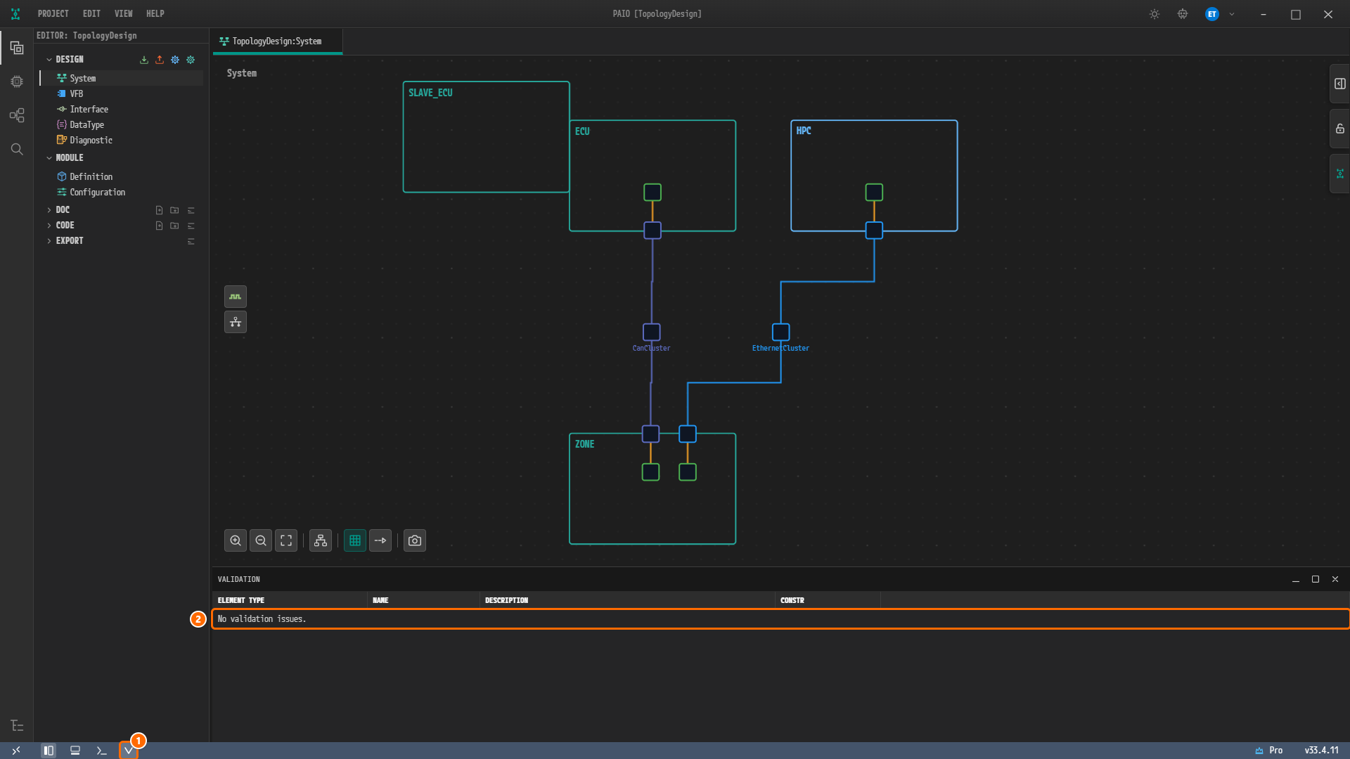
Figure 4-14. The VALIDATION panel after saving. ① The V icon in the footer, ② the row
No validation issues..
The validation result is zero findings, the same as at the end of CAN Bus. Creating EthernetCluster adds no UDP NM (network management) cluster to the design, because NM is off for a new cluster. The next section shows the tab where NM is turned on.
Note. While CONTROLLER of a connector was empty, the V icon showed the red badge
1. The badge disappears when the count drops back to zero, but the tooltip of the V icon keeps the last count,Validation: 1 error(s), 0 warning(s), 0 info(s). The VALIDATION panel shows the current result.
Checking the Network Management Tab
Opening the Cluster Configuration Window
-
Click the V icon in the footer again to close the VALIDATION panel.
-
Double-click the
EthernetClustersquare on the canvas. The window Communication Cluster Configuration [EthernetCluster] opens. Its tabs are CLUSTER, NM CLUSTER and TIME DOMAIN, and it first shows the CLUSTER tab: the table PDU TRIGGERINGS [PHYSICALCHANNEL VLAN 13] readsNo PDU triggering. [+] adds a PDU of the Signal model., and SIGNAL LAYOUT readsSelect a frame or PDU triggering to see where it is sent and its signal layout.. -
Click the NM CLUSTER tab.
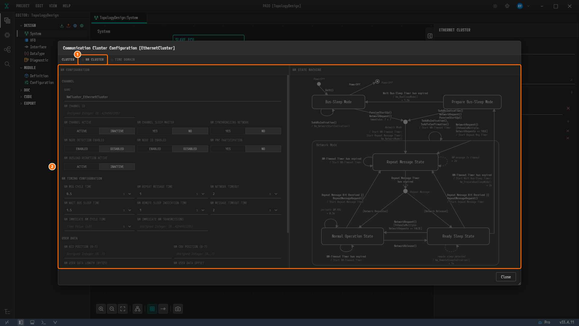
Figure 4-15. The NM CLUSTER tab. ① The tab NM CLUSTER with a hollow dot in front of its name, ② the dimmed editing area, which takes no input.
A hollow dot in front of a tab name means that the feature is off for this cluster. NM CLUSTER and TIME DOMAIN both carry it, and their names appear dimmed. Hovering over such a tab shows the tooltip Disabled. Right-click to enable., and right-clicking it opens a menu with one item, Enable.
While NM is off, the tab shows the NM editor only as a dimmed preview, and nothing in the preview is stored in the design. CHANNEL in NM CONFIGURATION on the left shows NAME NmCluster_EthernetCluster, and NM TIMING CONFIGURATION shows NM MSG CYCLE TIME 0.5, NM REPEAT MESSAGE TIME 1, NM NETWORK TIMEOUT 2, NM WAIT BUS SLEEP TIME 1.5, NM REMOTE SLEEP INDICATION TIME 1 and NM MESSAGE TIMEOUT TIME 2 (all in s). NM STATE MACHINE on the right is the NM state diagram.
Caution. Do not choose Enable. The reference design has no NM settings, so this tutorial leaves NM off for
EthernetCluster.
Closing the Window
- Click Close at the bottom right of the window. The window closes without a save prompt.
Note. Unlike the window of
CanClusterin CAN Bus, this window has no TRANSPORT PROTOCOL tab. PAIO offers that tab only for CAN and LIN clusters.
Validating Again
- Click the V icon in the footer to open the VALIDATION panel. It still shows
No validation issues., and the tabTopologyDesign:Systemcarries no modified mark.
Closing the window without choosing Enable leaves the design as it was, and this result is expected.
Values Without an Input Field
The Ethernet part of the reference design has values for which the System editor has no input field. You do not create these values in this chapter. The difference in the export result is covered in ARXML Export.
| Value in the reference design | Location | System editor |
|---|---|---|
Protocol name PROTOCOL-NAME = IEEE 802.3 | EthernetCluster | The ETHERNET CLUSTER panel has no PROTOCOL section |
Category CATEGORY = WIRED | The channel, both controllers, both connectors | No field in the cluster, controller or connector panels |
WAKE-UP-BY-CONTROLLER-SUPPORTED = false | EthernetController of HPC | No field in the ETHERNET CONTROLLER panel |
VLAN name Vlan_13 | The channel | Only a VLAN ID field, no name field |
Endpoint names ZONE_Endpoint, HPC_Endpoint, SOMEIP_SD_Multicast | The channel | Endpoints are entered through the address fields of the connectors, with no name field |
Why Is It Designed This Way?
- The Ethernet bus joins
ZONEandHPC. In the reference design, the channelPhysicalChannelofEthernetClusterholds the connectorsEthernetConnectorofZONEandHPC, in that order. You create the cluster from theZONEside to match this order. - The controller names differ per node, while the connector names are the same. The reference design calls the controller of
ZONEEthernetCommControllerand the controller ofHPCEthernetController, and calls both connectorsEthernetConnector. Since the nodes differ, the names may be the same. - Addresses go on the connectors. The three endpoints of the reference design become the unicast address of the
ZONEconnector, the unicast address of theHPCconnector and the multicast address of theHPCconnector. - The
HPCconnector is built with the reference design corrected. In the reference design this connector has no controller and points to the address ofZONE. Following it as is would give both connectors the same address and leave theHPCaddress192.168.0.11unused, so this tutorial builds it with the own controller and address ofHPC. - The VLAN ID is
13. The channel of the reference design has a VLAN whose VLAN ID is13. - MAC LAYER TYPE is left empty. The toggle value
XMIIdiffers from the AUTOSAR schema valueX-MII, so clicking it exports a value that is not in the schema. - NM stays off. The reference design has no NM settings. NM is turned on per cluster with Enable on the NM CLUSTER tab, and a new cluster has it off, so you leave it off and
EthernetClustergets no UDP NM cluster.
Checklist
- The node
ZONEhas the Ethernet controllerEthernetCommController(MAC ADDRESS11:22:ee:44:55:66) and the Ethernet connectorEthernetConnector(CONTROLLER =EthernetCommController, UNICAST IPV4 ADDRESS192.168.0.19, FIXED). - The node
HPChas the Ethernet controllerEthernetController(MAC ADDRESS00:11:22:33:44:55) and the Ethernet connectorEthernetConnector(CONTROLLER =EthernetController, UNICAST IPV4 ADDRESS192.168.0.11, FIXED, MULTICAST IPV4 ADDRESS224.0.0.1). - MAC LAYER TYPE of both Ethernet controllers has all three values off.
- Selecting the cluster
EthernetClustershows CHANNEL NAMEPhysicalChanneland VLAN ID13, and listsZONE/EthernetConnectorandHPC/EthernetConnector, in that order, under Connected Connectors (2). - In Communication Cluster Configuration [EthernetCluster], the tabs NM CLUSTER and TIME DOMAIN have a hollow dot in front of their names.
- The tab
TopologyDesign:Systemcarries no modified mark. - The VALIDATION panel shows
No validation issues..
Next Step
In LIN Bus you create LIN controllers and connectors on the nodes ECU and SLAVE_ECU and join them with the LIN cluster LinCluster.