ECU Properties
What You Will Do
In this chapter you fill in properties of the nodes you placed in Project and Nodes.
First, in the System editor, you turn on the POWER MANAGEMENT toggles SLEEP MODE SUPPORTED and WAKE-UP OVER BUS of the three ECU nodes (ECU, ZONE, SLAVE_ECU). You also confirm that the HPC node HPC has no such section.
Next, you open the SYSTEM panel of the System editor and change VERSION from 1.0.0 to 1.0.0;POPCORNSAR.
When you finish this chapter, the power management settings of the three ECU nodes and the system version are saved, and the VALIDATION panel still shows No validation issues..
Before You Begin
- Start after finishing Project and Nodes. The System editor must hold the nodes
ECU,ZONE,SLAVE_ECU,HPC, saved in a 2x2 grid. - You may close the VALIDATION panel opened in chapter 1. To follow along with the same screen as the figures, close the panel with the V icon (
Toggle Validation) in the footer.
You type only one value with the keyboard in this chapter. The rest is six clicks on toggle buttons (three ECU nodes × two toggles).
| Where | Item | Value |
|---|---|---|
System editor, nodes ECU, ZONE, SLAVE_ECU | POWER MANAGEMENT › SLEEP MODE SUPPORTED | On |
System editor, nodes ECU, ZONE, SLAVE_ECU | POWER MANAGEMENT › WAKE-UP OVER BUS | On |
System editor, node HPC | — | No change (check only) |
| System editor, SYSTEM panel | VERSION | 1.0.0;POPCORNSAR |
Turning On Power Management of the ECU Nodes
Selecting the ECU Node
-
If the tab
TopologyDesign:Systemis not open, click System under DESIGN in the EDITOR view. -
Click the header of the node
ECUon the canvas. A property panel titled ECU opens on the right. -
Confirm that the POWER MANAGEMENT section of the panel holds two buttons, SLEEP MODE SUPPORTED and WAKE-UP OVER BUS, and that both are off.
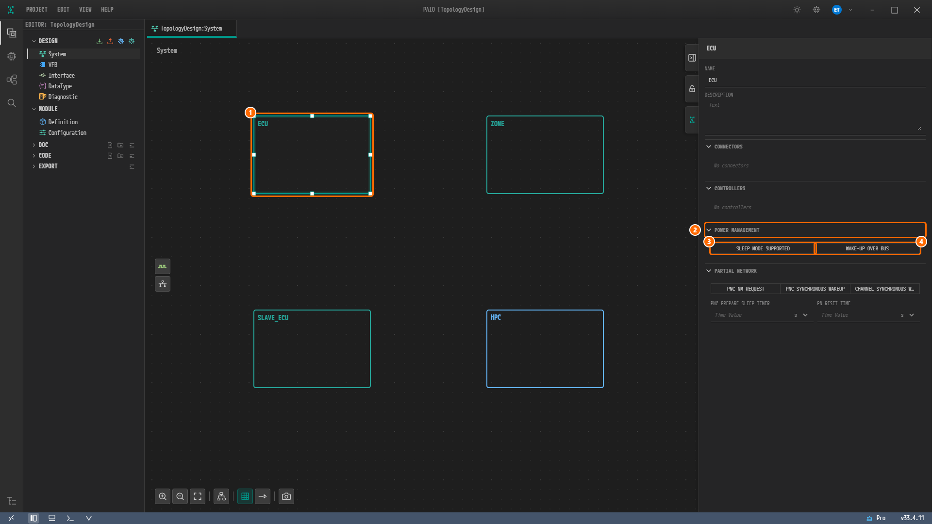
Figure 2-1. The System editor with the node
ECUselected. ① The selected nodeECU, ② the POWER MANAGEMENT section, ③ the SLEEP MODE SUPPORTED button, ④ the WAKE-UP OVER BUS button. A button that is off has no background and gray text.
From the top, the property panel of an ECU node holds NAME, DESCRIPTION, CONNECTORS (No connectors), CONTROLLERS (No controllers), POWER MANAGEMENT and PARTIAL NETWORK. This chapter deals only with POWER MANAGEMENT.
Turning On the Two Toggles
-
Click the SLEEP MODE SUPPORTED button.
-
Click the WAKE-UP OVER BUS button. The two buttons turn on and off independently, and both can be on.
-
Confirm that a blue dot (the modified mark) appears next to the tab title
TopologyDesign:System.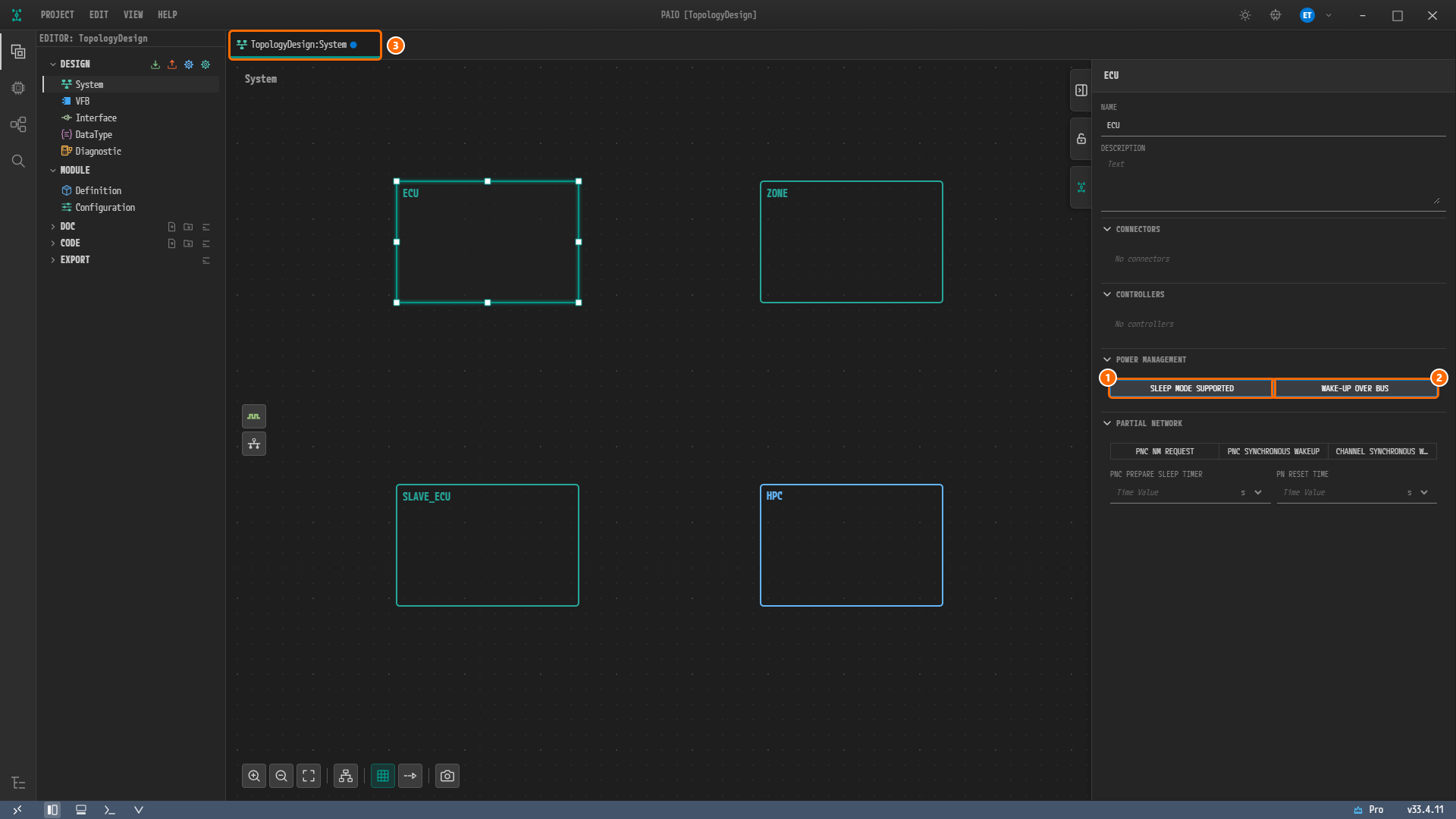
Figure 2-2. After turning on both toggles. ① SLEEP MODE SUPPORTED, ② WAKE-UP OVER BUS, ③ the tab
TopologyDesign:Systemwith the modified mark. A button that is on has a gray filled background and white text.
Turning Them On for ZONE and SLAVE_ECU
- Click the header of the node
ZONEon the canvas. The panel title is again ECU, and the NAME field showsZONE. - Click SLEEP MODE SUPPORTED and WAKE-UP OVER BUS to turn both on.
- Turn on the two toggles of the node
SLAVE_ECUin the same way.
The values for the three ECU nodes are collected below.
| Node | Panel title | SLEEP MODE SUPPORTED | WAKE-UP OVER BUS |
|---|---|---|---|
ECU | ECU | On | On |
ZONE | ECU | On | On |
SLAVE_ECU | ECU | On | On |
HPC | HPC | No section | No section |
Note. The panel title is the node kind, not the node name. All three ECU nodes show the title ECU, so check the NAME field to see which node you are editing.
Checking the HPC Node
You do not change any value in this step.
-
Click the header of the node
HPCon the canvas. -
Confirm that the panel title is HPC and that there is no POWER MANAGEMENT section.
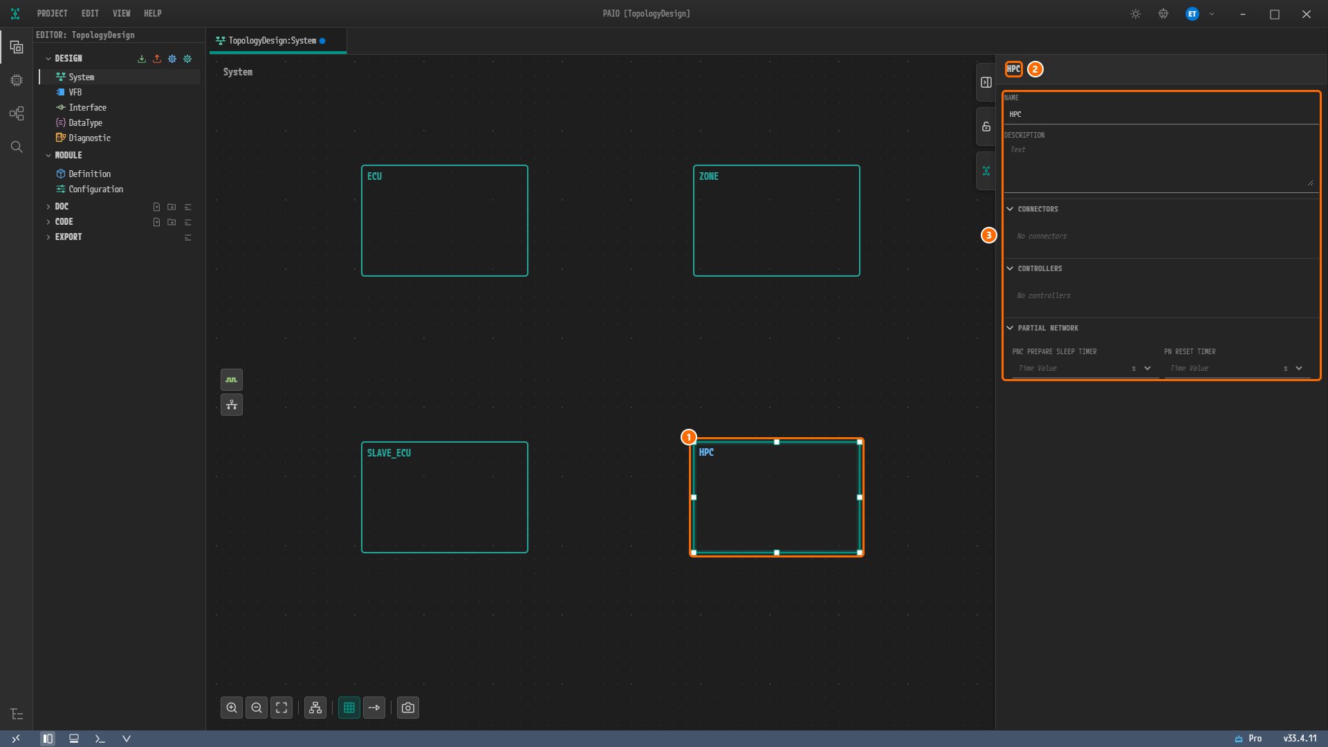
Figure 2-3. The node
HPCselected. ① The selected nodeHPC, ② the panel title HPC, ③ all items of the panel. There are only NAME, DESCRIPTION, CONNECTORS, CONTROLLERS and PARTIAL NETWORK; POWER MANAGEMENT is absent. The modified mark on the tab comes from the three ECU nodes changed earlier.
Note. The ECU
ECUof the reference design has two partitions,ECU_Partition0(EXEC-IN-USER-MODEtrue) andECU_Partition1(EXEC-IN-USER-MODEfalse). The System editor of PAIO has no field for entering partitions, and the ARXML export contains no partitions either. This tutorial does not create partitions.
Saving the System Editor
- Click the empty canvas between the four nodes. The selection clears and the property panel collapses.
- Press
Ctrl+Sto save. The blue dot on the tab titleTopologyDesign:Systemdisappears.
Changing the System Version
Opening the SYSTEM Panel
-
Click the System button (the PAIO logo, tooltip
System) on the right edge of the canvas. It is the third of the three vertical buttons there, below the panel toggle and the lock. -
The property panel expands with the title SYSTEM, and the three buttons move to the left edge of the panel. No new tab opens: the only tab is still
TopologyDesign:System, and it carries no modified mark.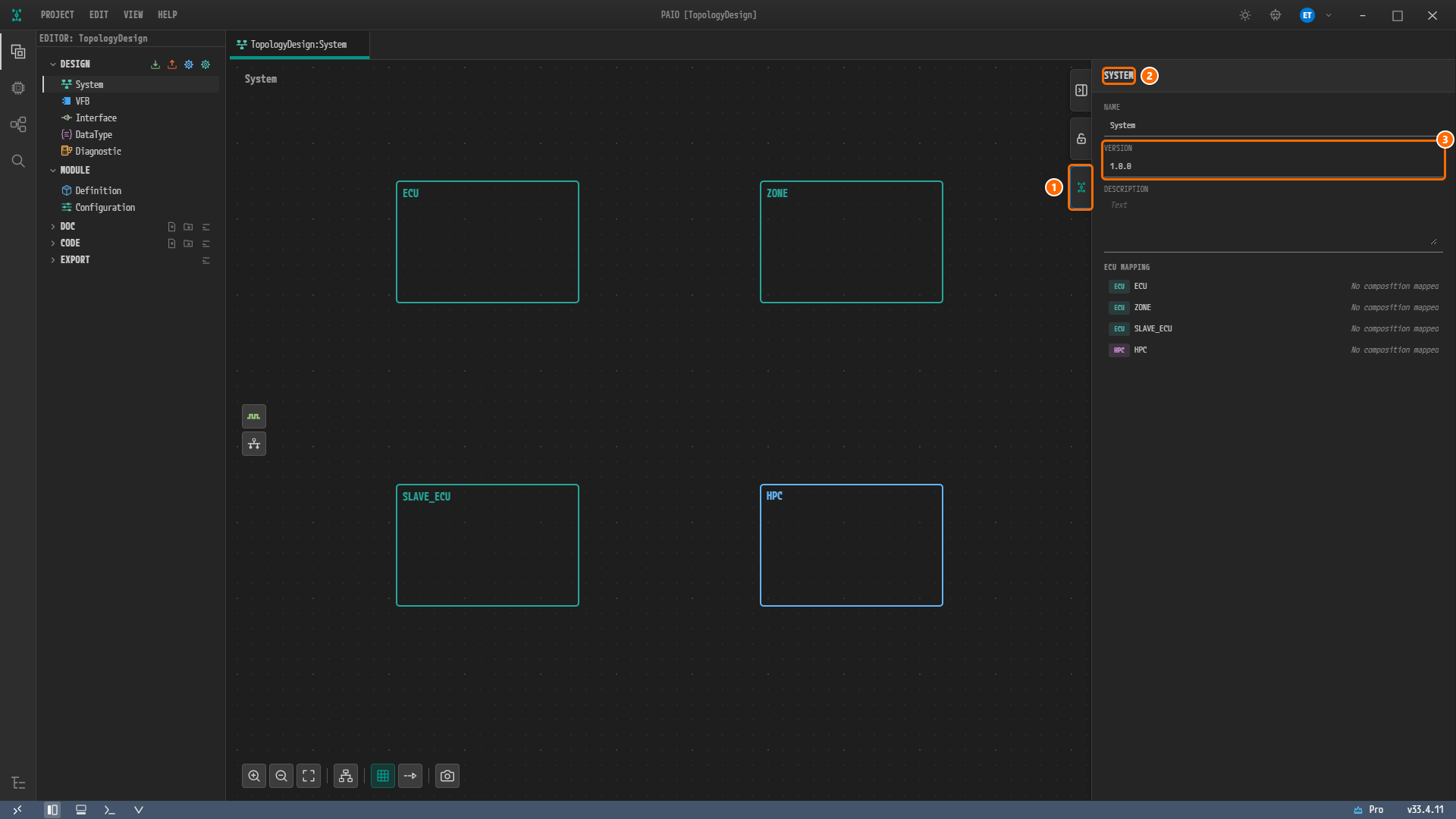
Figure 2-4. The SYSTEM panel. ① The System button, ② the panel title SYSTEM, ③ the default value
1.0.0in the VERSION field. ECU MAPPING below the fields shows the four nodes of the canvas.
The SYSTEM panel holds the following items.
| Item | What you see now | In this tutorial |
|---|---|---|
| NAME | System | Not changed |
| VERSION | 1.0.0 | Changed to 1.0.0;POPCORNSAR |
| DESCRIPTION | Empty | Left empty |
| ECU MAPPING | ECU, ZONE, SLAVE_ECU, HPC, each with No composition mapped | Check only |
The ECU and HPC badges in front of each ECU MAPPING row are the node kinds. Clicking a row selects that node on the canvas and switches the panel back to the node's properties; it changes no value.
Entering VERSION
-
In the VERSION field, select
1.0.0and type1.0.0;POPCORNSARover it. Each keystroke is saved todesign/SYSTEM.io.modelat once. While you type the first characters, the field shows the warningMust be major.minor.patch (e.g. 1.0.0); it disappears once1.0.0is typed. -
Press the
Tabkey. The focus moves to DESCRIPTION. Leave DESCRIPTION empty. The value is already saved, so no blue dot appears on the tabTopologyDesign:Systemand there is nothing to save withCtrl+S.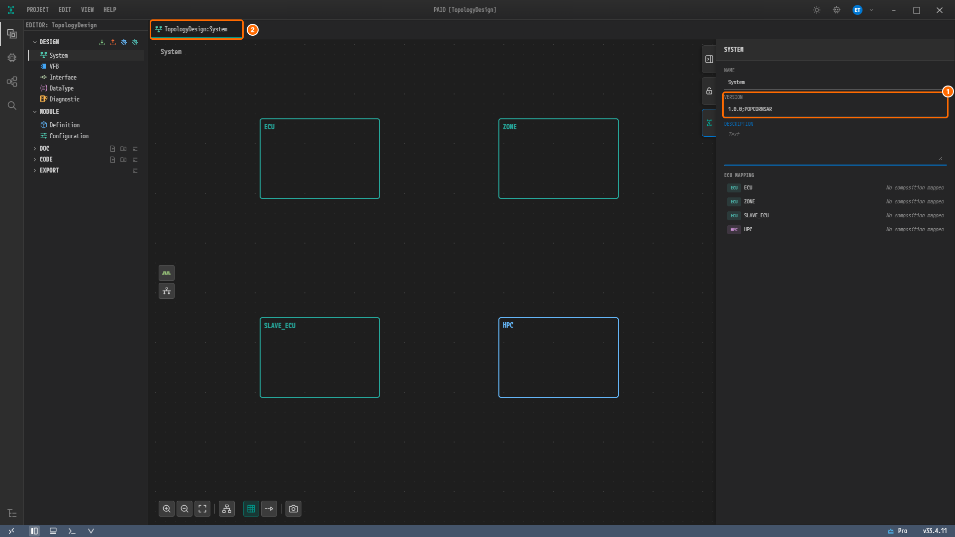
Figure 2-5. After entering the value. ① VERSION =
1.0.0;POPCORNSAR, ② the tabTopologyDesign:Systemwithout the modified mark. The DESCRIPTION label, which now has the focus, appears blue. -
Confirm that ECU MAPPING below the fields holds four rows,
ECU,ZONE,SLAVE_ECUandHPC, each withNo composition mapped.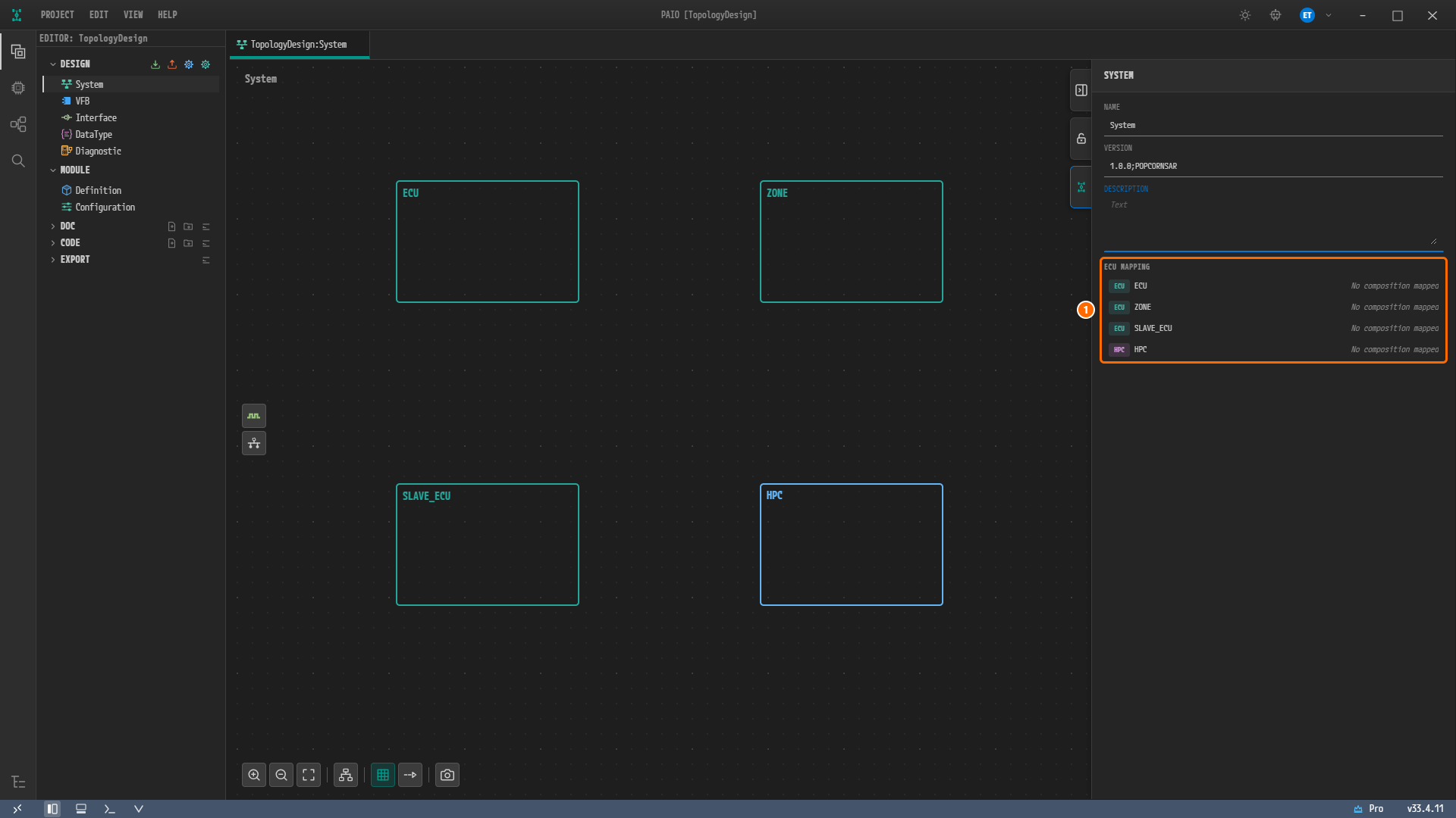
Figure 2-6. ECU MAPPING in the SYSTEM panel. ① The four rows
ECU,ZONE,SLAVE_ECU,HPC, each withNo composition mapped. VERSION is1.0.0;POPCORNSAR.
A ; in VERSION produces no error or warning text.
The SYSTEM panel writes only the field you change into the system information design/SYSTEM.io.model. ECU MAPPING shows the nodes on the canvas and is not written into that file. The three ECUs and the one HPC that the system references in ARXML Export come from the nodes on the canvas.
Viewing the Validation Result
-
Click the V icon (tooltip
Toggle Validation) in the footer to open the VALIDATION panel.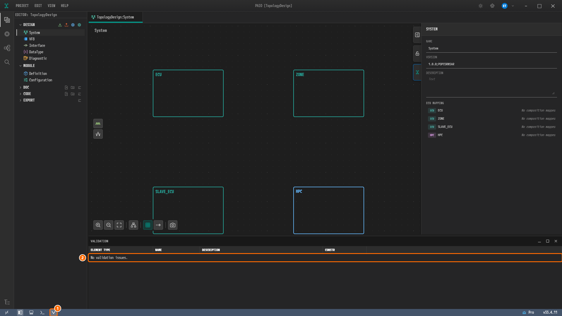
Figure 2-7. The VALIDATION panel. ① The V icon in the footer, ② the row
No validation issues.. The editor area has only the tabTopologyDesign:System, and the SYSTEM panel stays open on the right.
The validation result is zero findings (0 errors, 0 warnings). It is the same as at the end of chapter 1, and this result is expected.
Why Is It Designed This Way?
- The three ECU nodes support sleep and wake-up over the bus. In the reference design, the ECUs
ECU,ZONEandSLAVE_ECUall haveSLEEP-MODE-SUPPORTEDandWAKE-UP-OVER-BUS-SUPPORTEDset totrue. The SLEEP MODE SUPPORTED and WAKE-UP OVER BUS toggles become these two values. HPChas no power management settings. An HPC node is stored as a different element (a machine design) from an ECU node, and that element has neither of these two attributes. That is why its panel has no POWER MANAGEMENT section either.- The system version is
1.0.0;POPCORNSAR. It becomesSYSTEM-VERSIONin the exported ARXML and equals the value of the reference design. - The SYSTEM panel writes only the field you change. Changing VERSION writes the version into the system information and nothing else. ECU MAPPING reads the four nodes from the canvas, so there is nothing to save for it.
- Partitions are not created. The System editor has no field for them and the export does not contain them, so the result of this tutorial has no
ECU_Partition0orECU_Partition1.
Checklist
- Selecting each of the nodes
ECU,ZONE,SLAVE_ECUshows both SLEEP MODE SUPPORTED and WAKE-UP OVER BUS of POWER MANAGEMENT turned on. - Selecting the node
HPCshows the panel title HPC and no POWER MANAGEMENT section. - The tab
TopologyDesign:Systemcarries no modified mark. - VERSION in the SYSTEM panel is
1.0.0;POPCORNSAR. - ECU MAPPING in the SYSTEM panel holds four rows:
ECU,ZONE,SLAVE_ECU,HPC. - The only open tab is
TopologyDesign:System. - The VALIDATION panel shows
No validation issues..
Next Step
In CAN Bus you create CAN controllers and connectors on the nodes ECU and ZONE and join them with the CAN cluster CanCluster.