Appendix
What You Will Do
This appendix is reference material, not a chapter you follow along with. Use it after finishing ARXML Export to review your design, or to find again which value you entered in which chapter.
- Checklist of the finished design — what the screen must show in a design finished through chapter 7
- All value tables — every value entered in chapters 1 to 6
- Project file layout — the files under
design/and the chapters that write them - Differences from the reference design — where your export differs from the reference design
System_Design.arxml, and why - Common problems — validation messages and symptoms, and the chapter that fixes each
Before You Begin
- The values in this appendix are the same as in the bodies of chapters 1 to 7. If a value looks different, follow the body of that chapter.
- The finished design is the state after Validation and ARXML Export. The VALIDATION panel shows
No validation issues..
Checklist of the Finished Design
Nodes and System
- The System editor (tab
TopologyDesign:System) holds the nodesECU,ZONE,SLAVE_ECUandHPC. The first three show the panel title ECU, andHPCshows HPC. - Selecting each of
ECU,ZONEandSLAVE_ECUshows both SLEEP MODE SUPPORTED and WAKE-UP OVER BUS of POWER MANAGEMENT turned on. - Selecting
HPCshows no POWER MANAGEMENT section. - VERSION in the SYSTEM panel is
1.0.0;POPCORNSAR, and ECU MAPPING holds four rows:ECU,ZONE,SLAVE_ECU,HPC.
CAN Bus
-
ECUhas the CAN controllerCanController(CAN on, four bit timing fields0) and the CAN connectorCanConnector(CONTROLLER =CanController). -
ZONEhas the CAN controllerCanCommControllerand the CAN connectorCanConnector(CONTROLLER =CanCommController). - CHANNEL NAME of the cluster
CanClusterisPhysicalChannel, and Connected Connectors (2) listsZONE/CanConnectorandECU/CanConnector, in that order. - In Communication Cluster Configuration [CanCluster], the tabs NM CLUSTER, TRANSPORT PROTOCOL and TIME DOMAIN have a hollow dot in front of their names.
Ethernet Bus
-
ZONEhas the Ethernet controllerEthernetCommController(MAC ADDRESS11:22:ee:44:55:66) and the Ethernet connectorEthernetConnector(CONTROLLER =EthernetCommController, UNICAST IPV4 ADDRESS192.168.0.19, FIXED). -
HPChas the Ethernet controllerEthernetController(MAC ADDRESS00:11:22:33:44:55) and the Ethernet connectorEthernetConnector(CONTROLLER =EthernetController, UNICAST IPV4 ADDRESS192.168.0.11, FIXED, MULTICAST IPV4 ADDRESS224.0.0.1). - All three values of MAC LAYER TYPE are off on both Ethernet controllers.
- CHANNEL NAME of the cluster
EthernetClusterisPhysicalChannel, VLAN ID is13, and Connected Connectors (2) listsZONE/EthernetConnectorandHPC/EthernetConnector, in that order. - In Communication Cluster Configuration [EthernetCluster], the tabs NM CLUSTER and TIME DOMAIN have a hollow dot in front of their names.
LIN Bus
-
ECUhas the LIN master controllerLinController_Master(PROTOCOL VERSIONLIN 2.0, TIME BASE1ms, TIME BASE JITTER1ms) and the LIN connectorLinConnector_Master(CONTROLLER =LinController_Master). -
SLAVE_ECUhas the LIN slave controllerLinSlaveController(PROTOCOL VERSIONLIN 2.0) and the LIN connectorLinConnector(CONTROLLER =LinSlaveController). - CHANNEL NAME of the cluster
LinClusterisPhysicalChannel, IDLE TIMEOUT is empty, and Connected Connectors (2) listsSLAVE_ECU/LinConnectorandECU/LinConnector_Master, in that order.
Validation and Export
- The VALIDATION panel shows
No validation issues., and the V icon in the footer has no badge. - The
exportfolder has the four filesTopologyDesign_COM.arxml,TopologyDesign_DataType.arxml,TopologyDesign_SWC.arxmlandTopologyDesign_System.arxml, and the status bar ofTopologyDesign_System.arxmlandTopologyDesign_COM.arxmlopened in the XML editor showsSchema: R25-11and✓ No problems. - The
HPCconnector inTopologyDesign_COM.arxmlpoints at/System/MachineDesign/HPC/EthernetControllerandHPC_EthernetConnector_Endpoint. - The tab
TopologyDesign:Systemcarries no modified mark.
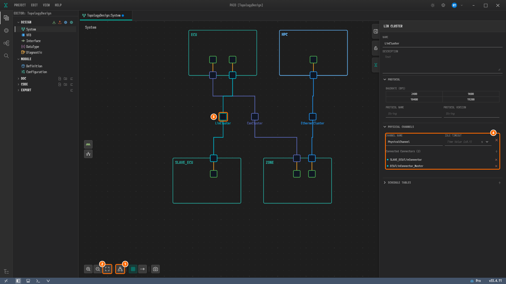
Figure 8-1. The System editor canvas of the finished design (Figure 5-14 in LIN Bus). ECU and HPC are at the top, SLAVE_ECU and ZONE at the bottom, and the cluster squares in the middle row are, from the left, LinCluster, CanCluster and EthernetCluster. ① Auto Layout, ② Fit to View, ③ LinCluster, ④ CHANNEL NAME PhysicalChannel, the empty IDLE TIMEOUT and Connected Connectors (2). The positions of nodes and clusters depend on the Auto Layout result and are not design values. The figure shows the state before Ctrl+S, so the tab still carries the modified mark.
All Value Tables
Project and System (Chapters 1 and 2)
| Item | Value | Chapter |
|---|---|---|
| Project name | TopologyDesign | 1 |
| System name | System (default of a new project, unchanged) | 1 |
| SYSTEM panel VERSION | 1.0.0;POPCORNSAR (default 1.0.0) | 2 |
| SYSTEM panel ECU MAPPING | ECU, ZONE, SLAVE_ECU, HPC (all No composition mapped, only checked) | 2 |
Nodes and Power Management (Chapters 1 and 2)
| Order added | Right-click position | Menu item | Default name | NAME | Panel title | SLEEP MODE SUPPORTED / WAKE-UP OVER BUS |
|---|---|---|---|---|---|---|
| 1 | Top left of the canvas | Add ECU | ECU_0 | ECU | ECU | On / on |
| 2 | Top right of the canvas | Add ECU | ECU_0 | ZONE | ECU | On / on |
| 3 | Bottom left of the canvas | Add ECU | ECU_0 | SLAVE_ECU | ECU | On / on |
| 4 | Bottom right of the canvas | Add HPC | HPC_0 | HPC | HPC | No section |
Keep the order ECU → ZONE → SLAVE_ECU → HPC. A node appears where you right-click, and Auto Layout is used from CAN Bus onward.
| Partition of the reference design | EXEC-IN-USER-MODE | This tutorial |
|---|---|---|
ECU_Partition0 (ECU) | true | Not created. The System editor has no input field for it |
ECU_Partition1 (ECU) | false | Not created. The System editor has no input field for it |
Controllers (Chapters 3 to 5)
| Node | Menu | Panel title | Default name | NAME | Other values | Chapter |
|---|---|---|---|---|---|---|
ECU | Add Controller › CAN | CAN CONTROLLER | ECU_Can_Controller_0 | CanController | CAN on, SYNC JUMP WIDTH, PROPAGATION SEGMENT, TIME SEGMENT 1, TIME SEGMENT 2 all 0 | 3 |
ZONE | Add Controller › CAN | CAN CONTROLLER | ZONE_Can_Controller_0 | CanCommController | CAN on, the four bit timing fields left empty | 3 |
ZONE | Add Controller › Ethernet | ETHERNET CONTROLLER | ZONE_Ethernet_Controller_0 | EthernetCommController | MAC ADDRESS 11:22:EE:44:55:66 entered (saved as 11:22:ee:44:55:66), MAC LAYER TYPE not clicked | 4 |
HPC | Add Controller › Ethernet | ETHERNET CONTROLLER | HPC_Ethernet_Controller_0 | EthernetController | MAC ADDRESS 00:11:22:33:44:55, MAC LAYER TYPE not clicked | 4 |
ECU | Add Controller › LIN Master | LIN MASTER | ECU_LinMaster_Controller_0 | LinController_Master | PROTOCOL VERSION LIN 2.0, TIME BASE 1 ms, TIME BASE JITTER 1 ms, WAKE-UP BY CONTROLLER not clicked | 5 |
SLAVE_ECU | Add Controller › LIN Slave | LIN SLAVE | SLAVE_ECU_LinSlave_Controller_0 | LinSlaveController | PROTOCOL VERSION LIN 2.0. The fields below it are left empty | 5 |
For TIME BASE and TIME BASE JITTER, change the unit box to ms first and then type 1. The saved value is 0.001, in seconds.
Connectors (Chapters 3 to 5)
| Node | Menu | Default name | NAME | CONTROLLER | Cluster / channel | Chapter |
|---|---|---|---|---|---|---|
ECU | Add Connector › CAN | ECU_Can_Connector_0 | CanConnector | CanController | CanCluster / PhysicalChannel | 3 |
ZONE | Add Connector › CAN | ZONE_Can_Connector_0 | CanConnector | CanCommController | CanCluster / PhysicalChannel | 3 |
ZONE | Add Connector › Ethernet | ZONE_Ethernet_Connector_0 | EthernetConnector | EthernetCommController | EthernetCluster / PhysicalChannel | 4 |
HPC | Add Connector › Ethernet | HPC_Ethernet_Connector_0 | EthernetConnector | EthernetController | EthernetCluster / PhysicalChannel | 4 |
ECU | Add Connector › LIN | ECU_Lin_Connector_0 | LinConnector_Master | LinController_Master | LinCluster / PhysicalChannel | 5 |
SLAVE_ECU | Add Connector › LIN | SLAVE_ECU_Lin_Connector_0 | LinConnector | LinSlaveController | LinCluster / PhysicalChannel | 5 |
After connecting, CONNECTED CHANNEL shows EthernetCluster / PhysicalChannel (VLAN: 13) on the Ethernet connectors and LinCluster / PhysicalChannel on the LIN connectors.
Clusters and Channels (Chapters 3 to 5)
| Cluster | Created from | Default name | Panel title | CHANNEL NAME | Channel value | Connected Connectors order | Chapter |
|---|---|---|---|---|---|---|---|
CanCluster | CanConnector of ZONE › + › Create CommunicationCluster [Can] | CanCluster_0 | CAN CLUSTER | PhysicalChannel (default) | — | ZONE/CanConnector, ECU/CanConnector | 3 |
EthernetCluster | EthernetConnector of ZONE › + › Create CommunicationCluster [Ethernet] | EthernetCluster_0 | ETHERNET CLUSTER | PhysicalChannel (default) | VLAN ID 13 | ZONE/EthernetConnector, HPC/EthernetConnector | 4 |
LinCluster | LinConnector of SLAVE_ECU › + › Create CommunicationCluster [Lin] | LinCluster_0 | LIN CLUSTER | PhysicalChannel (default) | IDLE TIMEOUT empty (10 ms is refused) | SLAVE_ECU/LinConnector, ECU/LinConnector_Master | 5 |
The second connector is connected with + › Connect to Channel... › the cluster name › PhysicalChannel. The Ethernet channel appears in the menu as PhysicalChannel (VLAN: 13). You do not enter a baud rate. None of the buttons of BAUDRATE (ARBITRATION, KBPS) in the CAN CLUSTER panel or BAUDRATE (BPS) in the LIN CLUSTER panel is on, but PAIO saves 500000 into CanCluster and 19200 into LinCluster.
Endpoints and VLAN (Chapter 4)
| Reference design element | Value | Where you enter it | Export name |
|---|---|---|---|
ZONE_Endpoint | 192.168.0.19 (FIXED) | UNICAST IPV4 ADDRESS and FIXED of ADDRESS SOURCE on the ZONE connector | ZONE_EthernetConnector_Endpoint |
HPC_Endpoint | 192.168.0.11 (FIXED) | UNICAST IPV4 ADDRESS and FIXED of ADDRESS SOURCE on the HPC connector | HPC_EthernetConnector_Endpoint |
SOMEIP_SD_Multicast | 224.0.0.1 | MULTICAST IPV4 ADDRESS on the HPC connector. MULTICAST PORT is left empty | HPC_EthernetConnector_Multicast |
Vlan_13 | VLAN-IDENTIFIER 13 | VLAN ID of the channel | VLAN_13 |
NM Clusters and TP Configurations (Chapters 3 to 5)
Network management (NM), the transport protocol (TP) and the time domain are turned on per cluster with Enable on the tabs of the Communication Cluster Configuration window that opens when you double-click the cluster. A new cluster has them all off. The reference design has neither NM nor TP, so this tutorial leaves them off, and the design has no NM cluster and no TP configuration.
| Cluster | Tabs of the window | Tabs left off | Chapter |
|---|---|---|---|
CanCluster | CLUSTER, NM CLUSTER, TRANSPORT PROTOCOL, TIME DOMAIN | NM CLUSTER, TRANSPORT PROTOCOL, TIME DOMAIN (hollow dot in front of the name) | 3 |
EthernetCluster | CLUSTER, NM CLUSTER, TIME DOMAIN | NM CLUSTER, TIME DOMAIN (hollow dot in front of the name) | 4 |
LinCluster | CLUSTER, TRANSPORT PROTOCOL | TRANSPORT PROTOCOL. Chapter 5 does not open the window | 5 |
A LIN cluster has no NM CLUSTER tab, because NM does not apply to LIN.
Defects in the Validation Chapter (Chapter 6)
Validation starts from a design that contains the three defects below and restores the original values. The fixed design is the same as the design at the end of LIN Bus.
| Location | Defect value | Fixed value | Validation error |
|---|---|---|---|
EthernetConnector of HPC › UNICAST IPV4 ADDRESS | 224.0.0.1 | 192.168.0.11 | constr_3288 |
LinConnector of SLAVE_ECU › CONTROLLER | Empty (Select controller...) | LinSlaveController | constr_5398 |
LinSlaveController of SLAVE_ECU › PROTOCOL VERSION | Empty (no button on) | LIN 2.0 | constr_5449 |
Project File Layout
The files of a project finished through chapter 7 are listed below. The right column names the chapters that create or change each file.
TopologyDesign/
├── TopologyDesign.io.prj
├── design/
│   ├── IVC.io.model                          Chapters 1 to 6
│   ├── SYSTEM.io.model                       Chapters 1, 2
│   └── VFB.io.model                          Chapter 1
└── export/
    ├── TopologyDesign_COM.arxml              Chapter 7
    ├── TopologyDesign_DataType.arxml         Chapter 7
    ├── TopologyDesign_SWC.arxml              Chapter 7
    └── TopologyDesign_System.arxml           Chapter 7
- The nodes, controllers, connectors and clusters are all stored in the single file
IVC.io.model, the model that the System editor edits. The design has no NM or TP configuration. View state such as node positions and the canvas zoom is stored in this file as well, and is not exported to ARXML. SYSTEM.io.modelholds the information of the systemSystem, such as VERSION. The SYSTEM panel writes VERSION into it as you type in ECU Properties. ECU MAPPING shows the nodes of the canvas and is not stored in this file.VFB.io.modelis a file the new project creates, and this tutorial does not change it.- The export does not change the files in
design/and writes only toexport/. - The project folder also has the folders
doc,code,workflowandimport. This tutorial does not use them.
Differences from the Reference Design
Your export has almost the same design content as the reference design file System_Design.arxml. The four nodes with their controllers and connectors, the sleep and bus wake-up settings, the three clusters and their channels, the addresses of the three endpoints, the VLAN ID and the system version are all there. Only the two partitions are missing as whole elements.
| Reference design | Your export | |
|---|---|---|
| Files | 1 | 4 |
| Elements with a name (packages excluded) | 29 | 79 |
| Elements with the same path | 1 | 1 |
| Elements moved to another package | 22 | 22 |
| Elements renamed in the same place | 4 | 4 |
| Elements only in the reference design | 2 | — |
| Elements only in your export | — | 52 |
Of the 27 elements that have a counterpart, 14 differ in values or references and 13 have the same values and references. The line numbers and the reason for each element are in the section "How Your Export Differs from the Reference Design" of ARXML Export.
Deliberate Departures in This Tutorial
| Difference | Reason | Chapter |
|---|---|---|
EthernetConnector of HPC has an extra COMM-CONTROLLER-REF (/System/MachineDesign/HPC/EthernetController), and its unicast endpoint is HPC_EthernetConnector_Endpoint (192.168.0.11) instead of ZONE_Endpoint | In the reference design this connector has no controller and points at the address of ZONE. Following it would give the two connectors the same address 192.168.0.19, and HPC_Endpoint would be used by no connector | 4, 7 |
The two Ethernet controllers have no MAC-LAYER-TYPE X-MII | Clicking XMII of MAC LAYER TYPE exports XMII, a value not in the schema, which the schema check of the XML editor reports as an error | 4 |
PAIO Naming Rules
| Difference | Content |
|---|---|
| Node packages | /System/VehicleTopology/Ecu/<node> becomes /System/EcuInstance/<node>. The HPC node is placed as a MACHINE-DESIGN in /System/MachineDesign/HPC |
| Cluster packages | /System/VehicleTopology/Cluster/… becomes /System/CommunicationCluster/Can/…, /System/CommunicationCluster/Ethernet/… and /System/CommunicationCluster/Lin/… |
| System category | CATEGORY SYSTEM_DESCRIPTION of SYSTEM becomes SYSTEM_DESIGN_DESCRIPTION |
| Endpoint names | ZONE_Endpoint, HPC_Endpoint and SOMEIP_SD_Multicast become ZONE_EthernetConnector_Endpoint, HPC_EthernetConnector_Endpoint and HPC_EthernetConnector_Multicast |
| VLAN name | Vlan_13 becomes VLAN_13. VLAN-IDENTIFIER 13 is the same |
| MAC address notation | 11:22:EE:44:55:66 goes out in lowercase as 11:22:ee:44:55:66. It is the same address |
| Empty CAN controller | CanCommController has no empty CAN-COMMUNICATION-CONTROLLER-CONDITIONAL. The design content is the same |
Elements PAIO Adds on Its Own
| Element | Content | Chapter |
|---|---|---|
BAUDRATE 500000, 19200 | Values PAIO saves into a new CAN cluster and a new LIN cluster | 3, 5 |
SERVICE-DISCOVERY-CONFIGS of HPC, 2 SD socket elements | When the HPC connector has a MULTICAST IPV4 ADDRESS, the export creates the SD configuration, the socket HPC_EthernetConnector_Multicast_Socket and the APPLICATION-ENDPOINT ApplicationEndpoint | 4 |
ASSIGNMENT-PRIORITY 0 and TTL 0 of the multicast endpoint | Values the export puts into a multicast endpoint | 4 |
| 49 basic data types | The SW-BASE-TYPE, IMPLEMENTATION-DATA-TYPE and other data type elements of TopologyDesign_DataType.arxml. This design does not use them | 7 |
The root composition System | The ROOT-SW-COMPOSITION-PROTOTYPE that the system of a new project has | 1 |
The export has no NM or TP elements, because this design leaves NM and TP off on every cluster that offers them.
Values You Do Not Create on Screen
| Reference design value | Location | Your export | Chapter |
|---|---|---|---|
ECU_Partition0 (EXEC-IN-USER-MODE true), ECU_Partition1 (false) | ECU | None. The System editor has no field for partitions | 2 |
PROTOCOL-NAME CAN-FD | CanCluster | None. PROTOCOL NAME of the CAN CLUSTER panel is left empty | 3 |
PROTOCOL-NAME IEEE 802.3 | EthernetCluster | None. The ETHERNET CLUSTER panel has no PROTOCOL section | 4 |
CATEGORY WIRED | The Ethernet channel, 2 controllers, 2 connectors | None. There is no field for it | 4 |
WAKE-UP-BY-CONTROLLER-SUPPORTED false | EthernetController of HPC | None. The ETHERNET CONTROLLER panel has no field for it | 4 |
WAKE-UP-BY-CONTROLLER-SUPPORTED true | LinController_Master | None. WAKE-UP BY CONTROLLER of the LIN MASTER panel is not clicked | 5 |
BUS-IDLE-TIMEOUT-PERIOD 0.01 | PhysicalChannel of LinCluster | None. IDLE TIMEOUT accepts only 0.1 seconds or more | 5 |
CREATE-ECU-WAKEUP-SOURCE false | EthernetConnector of HPC | None. You do not touch PARTIAL NETWORK › CREATE ECU WAKEUP SOURCE of the connector, so it has no value, and items without a value are left out of the export | 7 |
Defects on the Reference Design Side
| Difference | Content |
|---|---|
EthernetConnector of HPC | It has no COMM-CONTROLLER-REF, and its unicast endpoint is the address of ZONE, ZONE_Endpoint (192.168.0.19). HPC_Endpoint (192.168.0.11) is used by no connector. The error constr_5398 for a connector without a controller checks only the connectors of ECU nodes, so importing the reference design into PAIO as is and validating it gives No validation issues. |
In addition, the reference design has a UUID attribute on all 33 elements with a name, and your export has none. The element order also differs. The namespace http://autosar.org/schema/r4.0 and the schema AUTOSAR_00054.xsd are the same.
Common Problems
| Symptom or validation message | Cause | Fix | Chapter |
|---|---|---|---|
Connector "EthernetConnector" unicast IPv4 "224.0.0.1" is not in the unicast range (first octet 224 > 223). (constr_3288) | UNICAST IPV4 ADDRESS of the HPC connector holds a multicast address. Clicking the row selects the connector of ZONE | Click the HPC connector directly on the canvas, enter 192.168.0.11 in UNICAST IPV4 ADDRESS and press Ctrl+S | Ethernet Bus, Validation |
Connector "LinConnector" on "SLAVE_ECU" has no commController reference; each CommunicationConnector shall reference exactly one communication controller. (constr_5398) | CONTROLLER of the connector is empty. Clicking the row selects this connector | Choose LinSlaveController in the CONTROLLER list and press Ctrl+S | LIN Bus, Validation |
LIN slave controller "LinSlaveController" on "SLAVE_ECU" has no protocolVersion. (constr_5449) | No button of PROTOCOL VERSION is on. Clicking the row selects the node SLAVE_ECU | Click the controller square inside the node, click LIN 2.0 under PROTOCOL VERSION and press Ctrl+S | LIN Bus, Validation |
| TIME BASE becomes one second, IDLE TIMEOUT ten seconds | The unit box defaults to s | Change the unit box to ms first, then type the number. For IDLE TIMEOUT, delete the number and press the Tab key so that the field is empty | LIN Bus |
| An extra cluster appears | Create CommunicationCluster was clicked on the + badge of the second connector | Connect the second connector to the channel created earlier with Connect to Channel... on its + badge | CAN Bus, Ethernet Bus, LIN Bus |
| The order of Connected Connectors is the reverse of the reference design | The connector from which the cluster is created becomes the first connector of the channel | Create the CAN and Ethernet clusters from the connector of ZONE, and the LIN cluster from the connector of SLAVE_ECU | CAN Bus, Ethernet Bus, LIN Bus |
The exported Ethernet controller contains XMII, and the XML editor reports a schema error | XMII of MAC LAYER TYPE was clicked. The schema value is X-MII | Do not click MAC LAYER TYPE | Ethernet Bus |
| All three values of ADDRESS SOURCE are off | FIXED was not clicked | Click FIXED of ADDRESS SOURCE on both Ethernet connectors | Ethernet Bus |
| A MAC ADDRESS typed in uppercase is shown in lowercase | PAIO stores MAC addresses in lowercase | No fix is needed. It is the same address | Ethernet Bus |
| A value entered in the property panel is not applied | A field in the property panel commits its value only when you leave the field | Press the Tab key after entering a value | CAN Bus, Ethernet Bus, LIN Bus |
| Clicking the empty canvas does not clear the selection | The click landed on the edge of the canvas, especially near the toolbar at the bottom | Click the middle of the canvas where there is no node | Project and Nodes |
| The line numbers quoted in ARXML Export do not match your export | The nodes were added in a different order. The ECU nodes are saved and exported in the order you add them | Add the nodes in the order ECU → ZONE → SLAVE_ECU → HPC | Project and Nodes |
The + badge of the HPC connector is hard to click, or the third menu covers the earlier ones | The badge of the HPC connector is small, and near the right edge of the screen the menu opens to the left | Zoom in before clicking, or close the menu, click Zoom Out once more and open it again | Ethernet Bus |
Checklist
- Every item of "Checklist of the Finished Design" matches.
- The values in "All Value Tables" match the values on the screens of your design.
- The files under
design/match "Project File Layout". - The only differences between your export and the reference design are those in "Differences from the Reference Design".
Next Step
To change the design, go back to the chapter concerned, change the value, then follow Validation and ARXML Export again. To start over, return to the Network Topology Design Tutorial.