System Editor and Validation
What You Will Do
In this chapter you review the design you have built so far on two screens.
- SYSTEM panels: see the composition-to-ECU mappings in the System editor and the composition hierarchy of the whole vehicle in the VFB editor at a glance.
- VALIDATION panel: see the result of PAIO checking the model against AUTOSAR constraints (
constr_*) and against PAIO's own rules. Click an error row to jump to the offending element, then correct the value until there are zero errors.
When you finish this chapter you will know how to open and read the validation panel, and how to find the place to fix from an error row. The finished example is in the "No validation issues." state (zero errors), and that is also the target for the project you build by following along.
Before You Begin
- You must have completed PARA Platform Import and PNC Request Ports.
- The screens in this chapter show the finished example (
PNC). Figures 11-4 through 11-12, however, show a draft state in which the SOME/IP consumer ports collided with the providers. If you followed the previous chapters as written, you do not have these errors, so read those figures only to learn the procedure. - Where the project you build by following along differs from the finished example, see Appendix — Differences Between Your Project and the Finished Example.
- For the full feature set of the validation panel, see Validation in the PAIO manual; for the System editor, see System Editor.
Viewing the SYSTEM Panels
-
In the EDITOR view on the left, click System under DESIGN. The System editor opens in the tab
PNC:System. Then click the System button (the PAIO logo), the third of the three buttons on the right edge of the canvas. The properties panel opens with the title SYSTEM and shows NAME, VERSION, DESCRIPTION, and ECU MAPPING.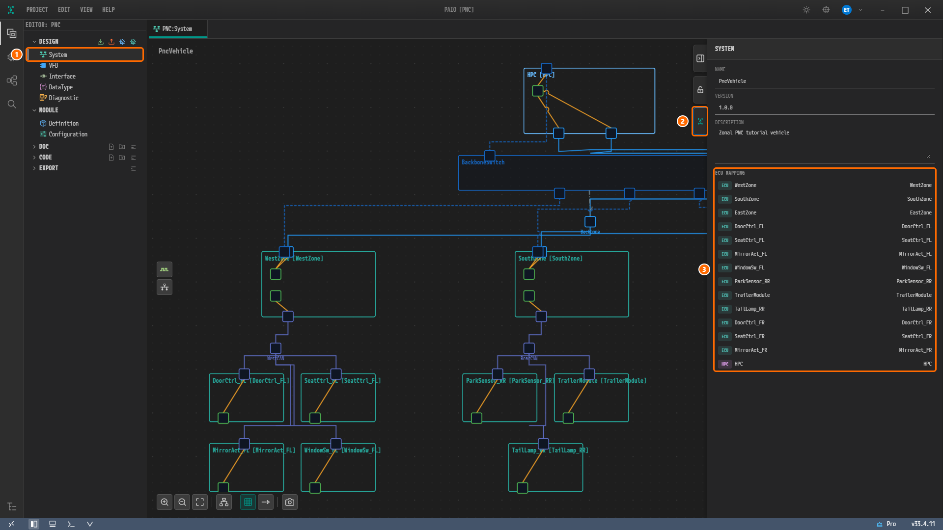
Figure 11-1. The System editor of the finished example with its SYSTEM panel open. The upper part of the panel holds NAME
PncVehicle, VERSION1.0.0, and DESCRIPTIONZonal PNC tutorial vehicle. ① System under DESIGN in the EDITOR view. ② The System button. ③ ECU MAPPING, with one row for each ECU and HPC node, 14 rows in all. -
Check the ECU MAPPING list. Each row is one ECU or HPC node on the canvas: the badge in front of the node name is the kind of node, and the composition mapped to that node is at the right end of the row. There are 14 rows in all.
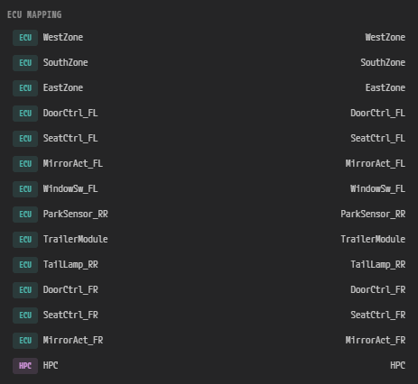
Figure 11-3. ECU MAPPING. The 13 rows with the ECU badge, from
WestZonetoMirrorAct_FR, come first, and the last row isHPCwith the HPC badge: 14 rows in all. Each node is mapped to the composition of the same name. -
In the EDITOR view, click VFB under DESIGN. The VFB editor opens in the tab
PNC:VFB. Click the System button on the right edge of this canvas as well. The properties panel shows NAME, VERSION, DESCRIPTION, ROOT COMPOSITION (PncVehicle), and the COMPOSITIONS tree.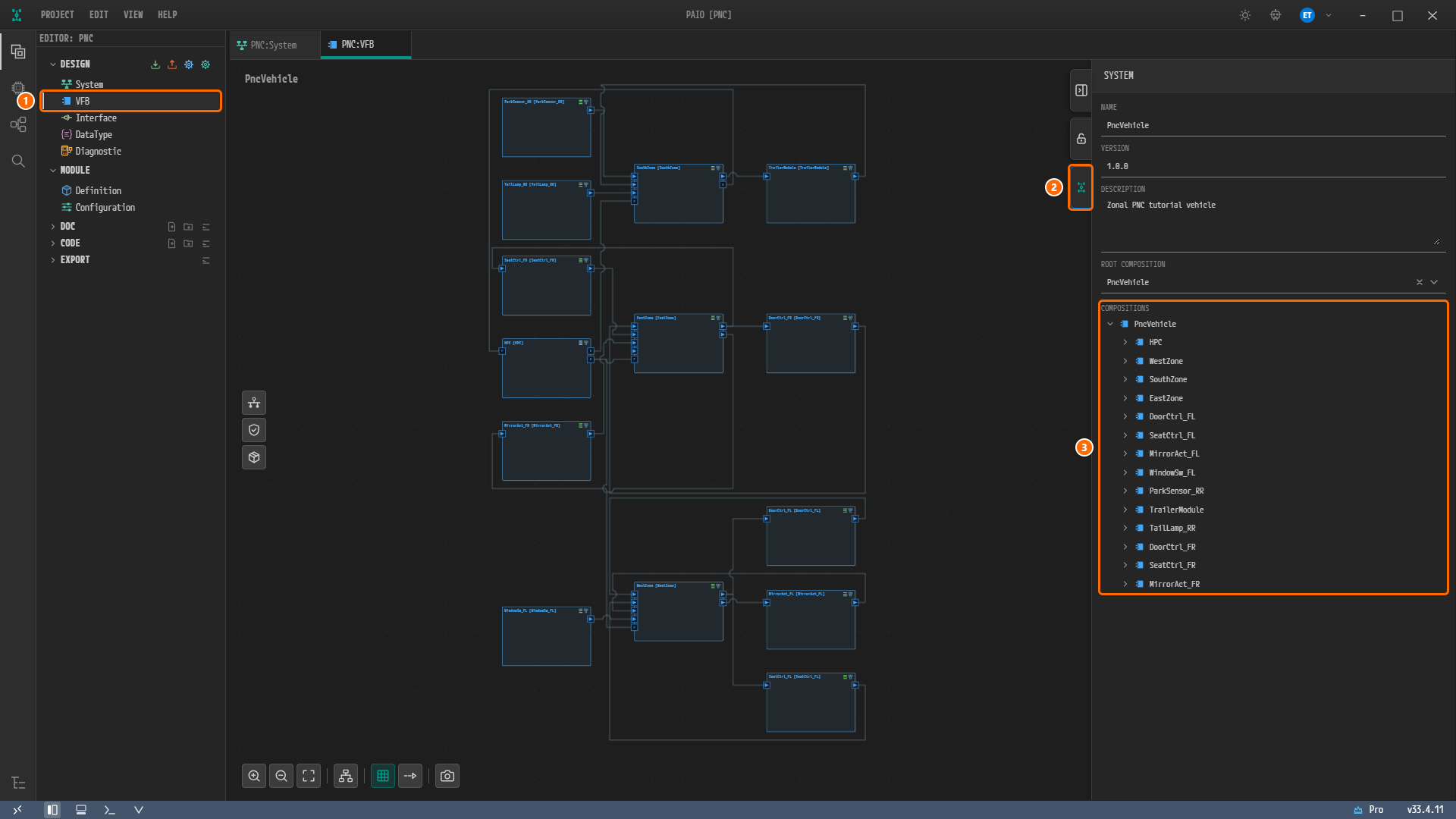
Figure 11-17. The VFB editor with its SYSTEM panel open, shown after the compositions are collapsed in step 4. ① VFB under DESIGN. ② The System button. ③ COMPOSITIONS.
-
In COMPOSITIONS, every row starts expanded, down to the SWCs inside each composition. Click the arrow to the left of each of the 14 compositions under the root
PncVehicleto collapse it. All 14 compositions then fit on one screen.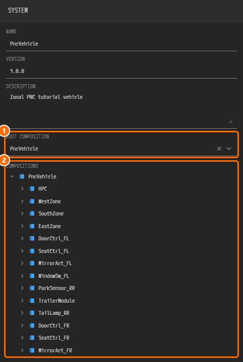
Figure 11-2. The SYSTEM panel of the VFB editor with every composition collapsed. ① ROOT COMPOSITION
PncVehicle. ② COMPOSITIONS: the rootPncVehiclewith the 14 compositions under it, fromHPCandWestZonetoMirrorAct_FR. A row shows an expand arrow, an icon for the kind of element, and the name (plus the type name when it differs). The tree has no column for the mapped node; you read the mapping in ECU MAPPING of the System editor (Figure 11-3).
Note.
PARAis the PARA platform composition contained inside theHPCcomposition; expandHPCin COMPOSITIONS to see it. BecauseHPCis already mapped to theHPCnode, you do not mapPARAseparately, soPARAdoes not appear in ECU MAPPING.
Note. Expanding or collapsing a composition row is only a view state. It does not add the unsaved-change marker (●) to the tab.
Note. Clicking a row in ECU MAPPING or COMPOSITIONS switches the properties panel to that node or composition (title ECU or COMPOSITION, for example). To return to the SYSTEM panel, click the System button again.
Opening the Validation Panel
Validation has no run button. PAIO checks the whole project as soon as the window opens it, and re-checks the model automatically whenever you edit or save it.
-
Check the title bar at the top of the window. It reads
PAIO [PNC], which means this window has the projectPNCopen. The whole project is checked without opening an editor. -
At the far left of the status bar at the bottom of the window sits a row of toggle buttons. The one whose tooltip reads Toggle Validation on hover is the validation icon (the
Vshape). When there are errors, a red number badge appears on the icon and the tooltip changes to the count per severity, such asValidation: 4 error(s), 0 warning(s), 0 info(s).If you followed the previous chapters as written, you do not have the SOME/IP port errors this section covers. The figure below shows the draft state in which the consumer ports collided.
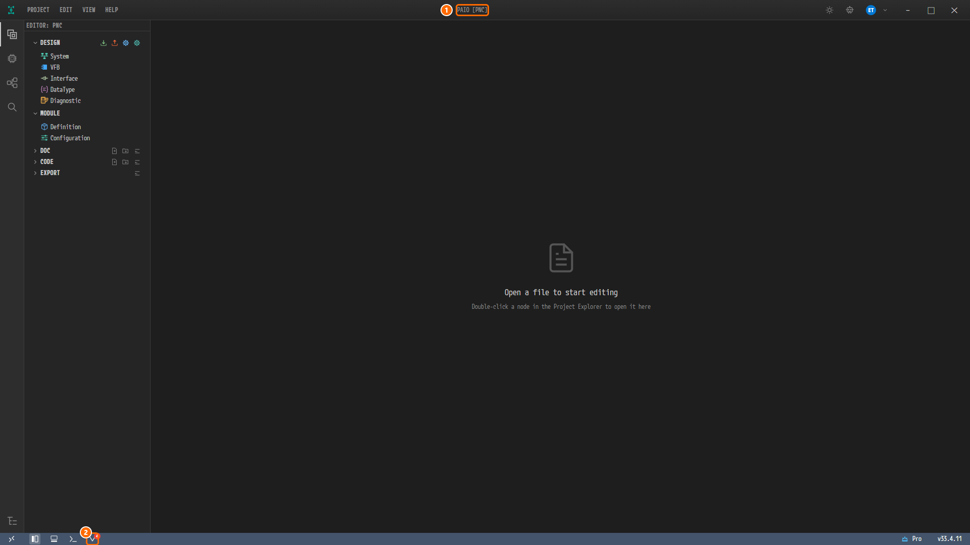
Figure 11-4. The window right after it opens the project in the draft state with colliding SOME/IP ports. ① The title bar
PAIO [PNC]. ② The validation icon in the status bar carries the red badge4, although nothing has been clicked yet. -
Click the validation icon. The VALIDATION panel opens below the editor area. Clicking the same icon again, or the × button at the top right of the panel, closes it.
Reading the Validation Panel
The VALIDATION panel is a table in which each row is one violation. The red badge next to the panel title is the error count.
| Column | Contents |
|---|---|
| ELEMENT TYPE | The kind of element that violates the rule. For example SomeipServiceInstanceToMachineMapping, PhysicalChannel, PncMapping |
| NAME | The element name. For example VehicleState_Consumer, Backbone/VLAN_Body |
| DESCRIPTION | An English sentence describing what is wrong |
| CONSTR | The number of the violated AUTOSAR constraint, such as constr_5093. It is empty for a PAIO rule that has no AUTOSAR number |
- Severity: a colored bar at the far left of the row. Red is error, orange is warning, and blue is info. Every row in this chapter is an error.
- Column width: a long DESCRIPTION sentence is truncated with
…. You can widen the column by dragging the border in the column header. The widened width is not stored in the model, and it returns to the default when you restart the app. In the figures below, the DESCRIPTION column is widened. - Click to navigate: hovering a row shows the tooltip
Go to the element to fix. Clicking the row opens the editor that holds the element and marks the element in red.

Figure 11-5. The VALIDATION panel showing four errors. The badge next to the title is 4. All four rows have ELEMENT TYPE SomeipServiceInstanceToMachineMapping and an empty CONSTR, which marks them as a PAIO rule. The description means that one address and port must be mapped to only one service instance. ① The VehicleState_Consumer row you click in the next section.
Finding and Fixing an Error: Duplicate SOME/IP Ports
This section walks through fixing a draft state in which two consumer instances used the same UDP port as the provider on the same connector. If you set the consumer ports to 30503 in Interfaces and SOME/IP Services, these errors do not appear. In that case, read along with the figures and apply the same sequence (click the row → find where to fix → correct the value → re-validate) to other errors.
| Connector (IP address) | Instance (role) | Draft UDP port | After the fix |
|---|---|---|---|
HPC_Eth_Rear_Conn (192.168.200.1) | VehicleState_Provider (P) | 30501 | 30501 (unchanged) |
HPC_Eth_Rear_Conn (192.168.200.1) | ParkDistance_Consumer (C) | 30501 | 30503 |
SouthZone_Eth_Conn (192.168.200.12) | ParkDistance_Provider (P) | 30502 | 30502 (unchanged) |
SouthZone_Eth_Conn (192.168.200.12) | VehicleState_Consumer (C) | 30502 | 30503 |
Finding the Element from an Error Row
-
In the VALIDATION panel, click the
VehicleState_Consumerrow.The
PNC:Interfacetab opens andSVC_VehicleStateis selected on the SERVICE tab. On the SERVICE INSTANCE tab on the right, theVehicleState_Consumercard expands with a red border.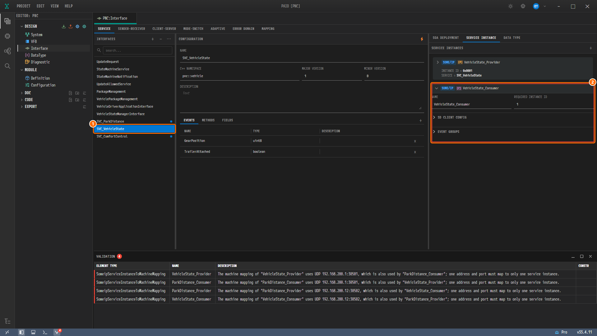
Figure 11-6. The result of clicking the row. ① The selected service interface
SVC_VehicleState. ② The SOME/IP CVehicleState_Consumercard marked with a red border (NAME, REQUIRED INSTANCE ID1). The panel below still holds all four errors.
Note. This card has no UDP port field. The address and port an instance is deployed on are set under SERVICE INSTANCES of the connector in the System editor. Because the place the error row points to differs from the place you correct the value, the next step moves to the System editor.
Fixing the SouthZone_Eth_Conn Port
-
In the EDITOR view on the left, click System under DESIGN to open the System editor (tab
PNC:System). -
On the canvas, click the Ethernet connector above the
SouthZonenode. Confirm that the properties panel on the right is titled ETHERNET CONNECTOR and that NAME isSouthZone_Eth_Conn. -
If SERVICE INSTANCES is collapsed, click it to expand it. Then click the
VehicleState_Consumerline to expand it. The IP ADDRESS192.168.200.12, TCP PORT, and UDP PORT30502fields appear, followed by the empty TLS (TCP) and TLS (UDP) rows.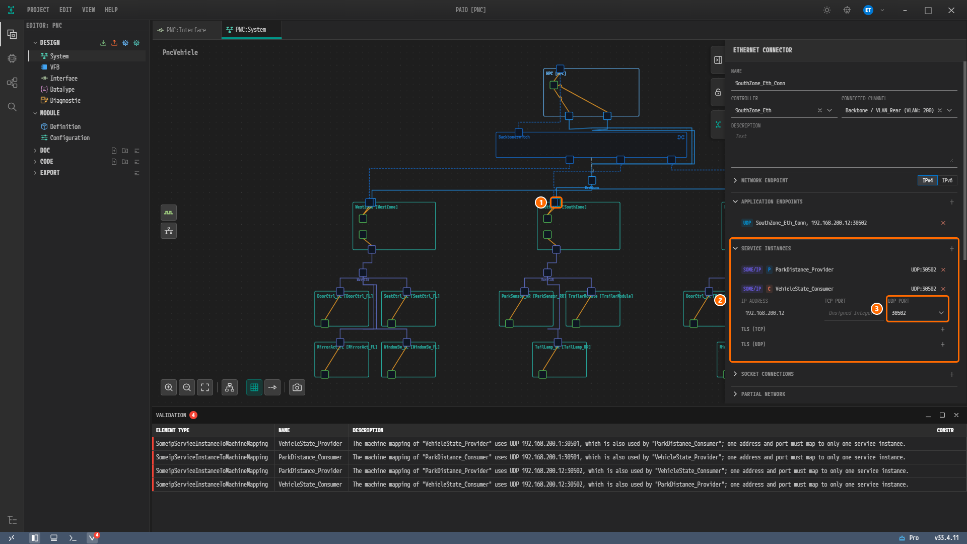
Figure 11-7. ① The selected connector
SouthZone_Eth_Conn. CONNECTED CHANNEL isBackbone / VLAN_Rear (VLAN: 200), and APPLICATION ENDPOINTS holds a single entry,SouthZone_Eth_Conn, 192.168.200.12:30502. ② SERVICE INSTANCES. Both PParkDistance_Providerand CVehicleState_Consumerare onUDP:30502. ③ The UDP PORT30502of the expandedVehicleState_Consumer. -
Type
30503in the UDP PORT field and press Tab.Note. The ▾ list to the right of UDP PORT offers only the Application Endpoint ports of this connector. If
30503is not in the list, type it directly. When you enter a new port, the Application Endpoint for that port (SouthZone_Eth_Conn, 192.168.200.12:30503) is added automatically.The model is re-checked immediately, without saving. The card collapses and the summary changes to
UDP:30503. The two port errors on theSouthZoneside disappear.Changing the port also makes PAIO derive the signals and PDUs of the SOME/IP services (CP-SOA derivation). The derivation writes the
SVC_…signals and PDUs todesign/SIGNAL.io.modelat once and adds theSVC_…_SRandSVC_…_CSinterfaces to the open Interface editor, so thePNC:Interfacetab gets the ● marker as well. The derived elements raise no validation error, so you do not need to undo the derivation. -
Click the
VehicleState_Consumerline again to expand the card, and confirm that UDP PORT is30503. Also confirm that the VALIDATION badge is2. The two remaining findings are on theHPC_Eth_Rear_Connside (192.168.200.1:30501).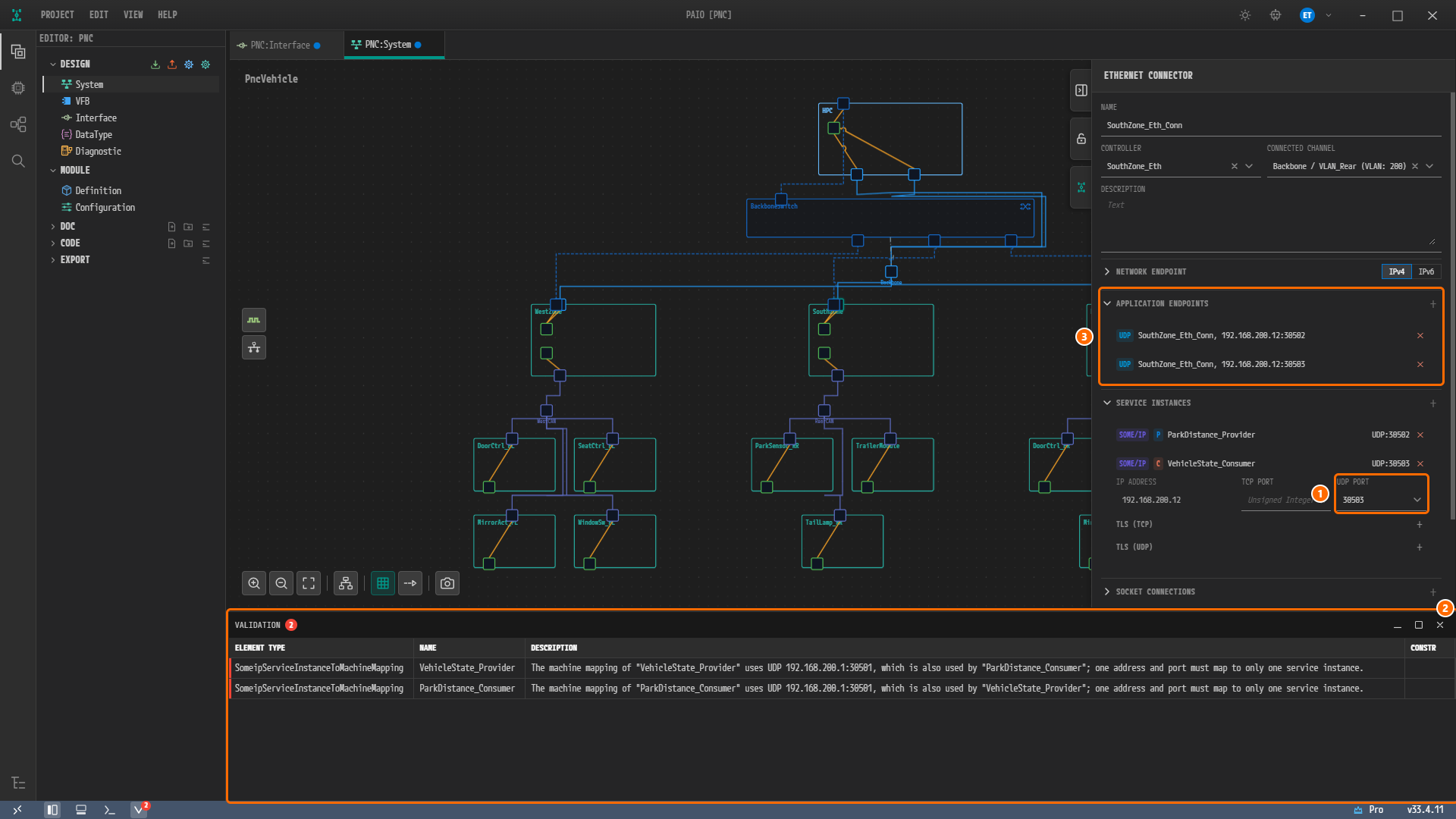
Figure 11-10.
SouthZone_Eth_Connright after the change, with theVehicleState_Consumercard expanded again. ① UDP PORT30503. ② The whole VALIDATION panel, outlined in orange. The badge next to the title is2.VehicleState_ProviderandParkDistance_Consumerstill share192.168.200.1:30501. ③...:30502and...:30503under APPLICATION ENDPOINTS. Both tabs carry ● (unsaved changes). -
Press
Ctrl+S. It saves the active tab,PNC:System, and the ● marker stays onPNC:Interface. Choose PROJECT › Save All to save that tab as well. The ● marker disappears from both tabs.
Fixing the HPC_Eth_Rear_Conn Port
Fix the two remaining findings the same way.
-
In the VALIDATION panel, click the
ParkDistance_Consumerrow. On thePNC:Interfacetab, theParkDistance_Consumercard is marked with a red border.
Figure 11-11. The panel after the first fix is saved. The badge is
2. ① TheParkDistance_Consumerrow to click. -
Return to the
PNC:Systemtab and click the right-hand one of the two connectors on the lower edge of theHPCnode.HPChas two Ethernet connectors (HPC_Eth_Body_ConnandHPC_Eth_Rear_Conn), so confirm that NAME isHPC_Eth_Rear_Connand CONNECTED CHANNEL isBackbone / VLAN_Rear (VLAN: 200). -
Under SERVICE INSTANCES, click the
ParkDistance_Consumerline to expand it. IP ADDRESS is192.168.200.1and UDP PORT is30501. Type30503in UDP PORT and press Tab. -
This time the card stays expanded, and UDP PORT reads
30503. Its summary line, however, still readsUDP:30501; it shows the new port once you select the connector again. -
Confirm that the panel shows "No validation issues.".
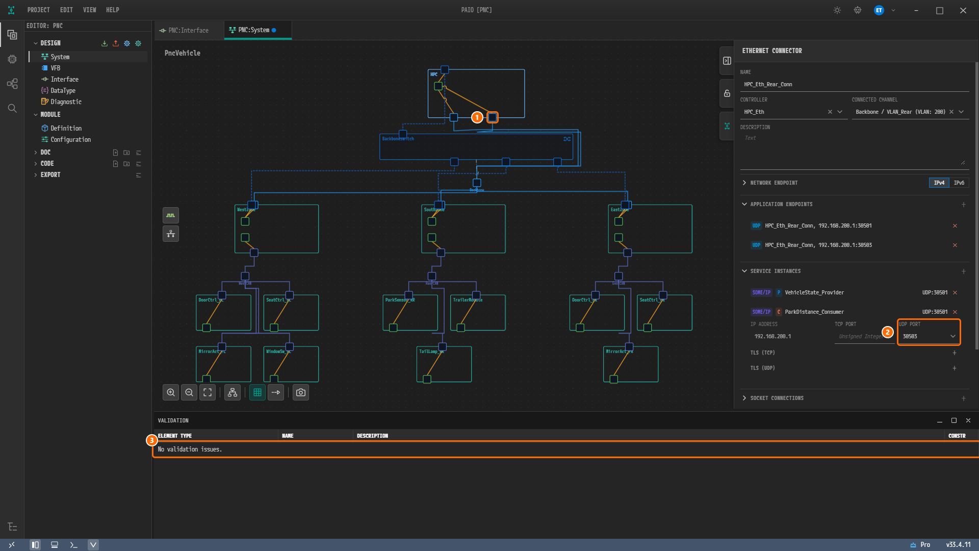
Figure 11-12. ① The selected connector
HPC_Eth_Rear_Conn. APPLICATION ENDPOINTS holds...:30501and...:30503. Under SERVICE INSTANCES, PVehicleState_Provideris onUDP:30501, and the summary line of CParkDistance_Consumerstill readsUDP:30501. ② UDP PORT30503. ③ "No validation issues.". ThePNC:Systemtab still carries ● because the change is not saved yet. -
Press
Ctrl+Sto save. This time onlyPNC:Systemcarries the ● marker, soCtrl+Sis enough.
Re-validating the Saved Result
-
You do not need to click anything: saving re-checks the project by itself.
-
Confirm that the panel shows "No validation issues." and that neither the panel title nor the status bar validation icon carries a badge.
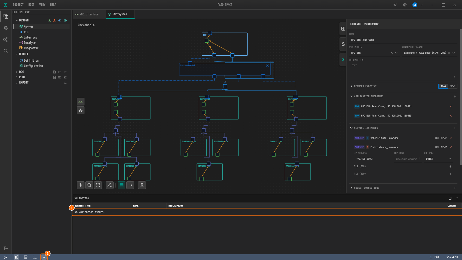
Figure 11-13. The screen after saving. ① "No validation issues.". ② The status bar validation icon without a badge. The summary line of
ParkDistance_Consumerin the properties panel readsUDP:30501until you select the connector again.
Figure 11-14. The VALIDATION panel with zero errors. There is no badge next to the title, and the table holds the single line "No validation issues.".
Checking Live Validation: PNC GATEWAY TYPE
Validation reacts to unsaved edits as well. Deliberately change one gateway setting in the finished example, then revert it and watch the errors disappear. You do not save in this section.
-
Open the
PNC:Systemtab (if the tab is closed, click System under DESIGN in the EDITOR view). Click the Ethernet connector above theEastZonenode and confirm that NAME isEastZone_Eth_Connand CONNECTED CHANNEL isBackbone / VLAN_Body (VLAN: 100). -
If PARTIAL NETWORK in the properties panel is collapsed, click it to expand it. PNC GATEWAY TYPE is set to PASSIVE.
-
Click ACTIVE. Two errors appear in the VALIDATION panel without saving.
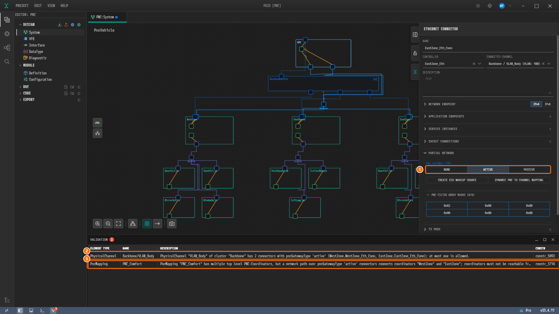
Figure 11-15. NETWORK ENDPOINT / APPLICATION ENDPOINTS / SERVICE INSTANCES / SOCKET CONNECTIONS in the properties panel are collapsed. ① ACTIVE selected among NONE / ACTIVE / PASSIVE of PNC GATEWAY TYPE. ② The
PhysicalChannelBackbone/VLAN_Bodyrow,constr_5093: theVLAN_Bodychannel has two active connectors (WestZone_Eth_ConnandEastZone_Eth_Conn) where at most one is allowed. ③ ThePncMappingPNC_Comfortrow,constr_3714: the top-level PNC coordinatorsWestZoneandEastZoneofPNC_Comfortare connected to each other over an active connector path. The tab now carries the ● marker. -
Click PASSIVE again. Both rows disappear at once and the panel returns to "No validation issues.". The ● marker, however, stays on the tab, even though the setting is back to its saved value.
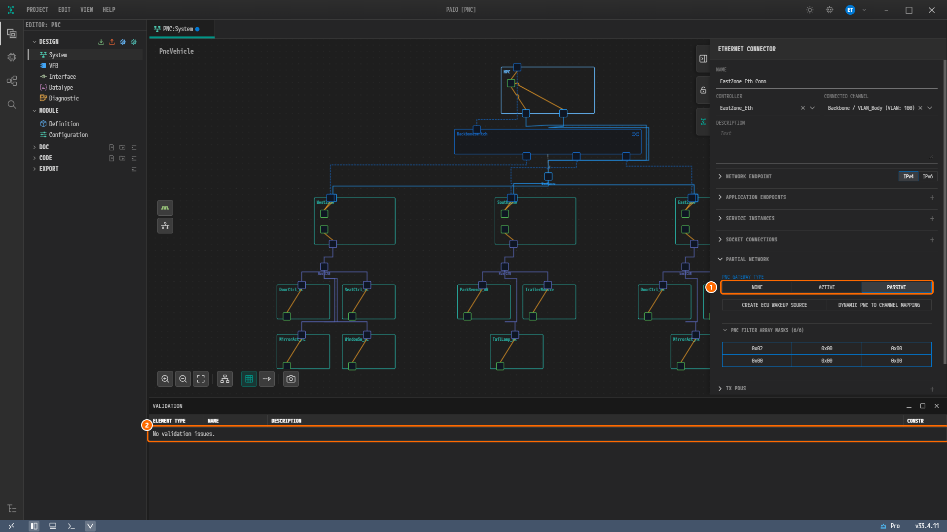
Figure 11-16. ① PNC GATEWAY TYPE back on PASSIVE. ② "No validation issues.". The ● marker next to the tab name is still there.
-
You do not save in this section, so close the tab without saving: hover over the
PNC:Systemtab and click the × (tooltip Close) that appears. When the Unsaved Changes window appears, click Don't Save.
Note. A single cause can violate several constraints at once. Switching only
EastZone_Eth_Connto ACTIVE reports both the channel rule (constr_5093) and the coordinator rule (constr_3714). Fixing the one cause clears both.
Key Constraints Related to PNC Design
The finished example satisfies every constraint below. This table lists what the validation panel reported while the example was first built, together with the correction applied. If you followed the previous chapters as written, these do not appear now. Should you see one of them, review the chapter it belongs to.
| Constraint | What the validation panel reported | Correction | Related chapter |
|---|---|---|---|
constr_3040 | PNC identifiers 8/9/10 lie outside the PNC vector bit range (16..63) | Changed the identifiers to 17/18/19 | PNC Definitions and Connector PNC Properties |
constr_3686 | The filter mask is 3 bytes, which differs from PNC VECTOR LENGTH 6 | Recalculated it to 6 bytes | Reviewing PDU GROUPS, MATRIX, and NM VECTOR |
constr_5093 | The backbone channel has three active gateway connectors | Split the backbone into VLAN_Body and VLAN_Rear, with one active connector per VLAN | Topology Design |
constr_3714 / constr_3781 | Top-level coordinators are connected over an active path / no coordinator exists | WestZone and SouthZone are active on both sides (top-level), and EastZone is passive on the backbone side | PNC Definitions and Connector PNC Properties |
constr_3514 | One I-signal (such as LockCmd) is mapped to two PDUs | Split the left and right signals into _FL and _FR | Signals, PDUs, Frames, and I-PDU Groups |
constr_9157–9159, constr_9162 | Mandatory properties of the CanNm cluster are missing | Filled in the four properties nmBusloadReductionActive, nmImmediateNmTransmissions, nmMessageTimeoutTime, and nmRemoteSleepIndicationTime on the CAN NM CLUSTER tab of the communication cluster dialog | NM Configuration |
constr_5222 | Mandatory properties of the UdpNm cluster are missing | Filled in nmMessageTimeoutTime and nmRemoteSleepIndicationTime on the UDP NM CLUSTER tab of the communication cluster dialog. The remaining mandatory values (nmMsgCycleTime, nmRepeatMessageTime, nmWaitBusSleepTime, nmNetworkTimeout) are filled with defaults when the NM cluster is created. NmCluster_VLAN_Rear cannot be opened from the screen, so it cannot be filled this way | NM Configuration |
constr_9165 / 9166 | Mandatory flags of the NM cluster coupling are missing | Couplings can be neither created nor corrected from the screen in the current version; their values arrive together with the ARXML on import | NM Configuration |
| (PAIO NM rule) | The NetworkHandle has no INACTIVE-to-FunctionGroup state mapping ("PNC release stops nothing") | Added the Off mappings for ParkAssistFG and TrailerFG | AP Machine — NM Handles and FunctionGroups |
constr_10641 | The max-action-list-duration of the SM module is missing | Set it to 1.0 s | AP Machine — NM Handles and FunctionGroups |
Why Aim for Zero Findings?
Design rationale. The validation panel is an informational tool; errors block neither saving nor export. Every item in the table above, however, turns into a real behavioral fault once another tool (a ComM/Nm configuration generator, for instance) interprets the exported ARXML. That is why you refine a PNC design until it reads "No validation issues.". Zero findings means the AUTOSAR constraints are satisfied; the ARXML schema (XSD) check is performed separately during export.
Check Your Work
- In the VFB editor's SYSTEM panel, COMPOSITIONS shows 14 compositions under the root
PncVehicle. - In the System editor's SYSTEM panel, ECU MAPPING lists 14 nodes (13 ECU, 1 HPC), each mapped to the composition of the same name.
- With the project open, the VALIDATION panel shows "No validation issues.", and the status bar validation icon carries no badge.
- When you select each connector,
ParkDistance_ConsumeronHPC_Eth_Rear_ConnandVehicleState_ConsumeronSouthZone_Eth_Connare both onUDP:30503. - PNC GATEWAY TYPE of
EastZone_Eth_Connis PASSIVE. - No tab name carries the unsaved-change marker (●).
Next Steps
In ARXML Export you export the validated design as ARXML documents and inspect the resulting files.