Reviewing PDU Groups, Matrix and NM Vector
What You Will Do
The viewer on the right side of the PNC (Partial Network Cluster) dialog has three tabs: PDU GROUPS, MATRIX and NM VECTOR. In this chapter you open all three in turn and cross-check the PNC design you entered in the previous chapters.
- PDU GROUPS: see which PNC each PDU belongs to.
- MATRIX: see the relationship between PNCs and physical channels in a single table.
- NM VECTOR: see where the PNC bits sit inside the NM PDU.
This chapter only reads. You do not change or save any value. When you finish, you know how to read all three tabs and which bit of the NM PDU a connector filter mask value corresponds to.
Before You Begin
- You must have finished The PNC Dialog — Binding Each PNC.
- This chapter starts from the state where every binding is complete and saved. If you followed the previous chapter through to the end, you continue from exactly that state. The completed state matches the table in Values for the Remaining PNCs.
- This is a read-only chapter. You do not change any value in the three tabs.
- The NM cluster and NM node that the NM VECTOR tab reads were filled in under NM Settings. Both elements are created automatically from the topology you drew in Topology Design. You enter the cluster's NM PNC PARTICIPATION and the NM timing in the communication cluster dialog, and the node's NM NODE ID and NM PDU in the NETWORK MANAGEMENT tab of the node dialog. If your values differ from the table, compare them against the All NM Values table in Chapter 3. For the full description, see IVC Editor.
- These are the main values you look at in this chapter.
| Item | Value |
|---|---|
| PNC | PNC_Comfort 17, PNC_ParkAssist 18, PNC_Trailer 19 |
| PNC VECTOR OFFSET / PNC VECTOR LENGTH | 2 / 6 (Byte 2 to 7 of the NM PDU, bits 16 to 63) |
| NM clusters | NmCluster_EastCAN, NmCluster_RearCAN, NmCluster_WestCAN (CanNm), NmCluster_VLAN_Body, NmCluster_VLAN_Rear (UdpNm) |
Opening the Viewer Tabs
-
In the EDITOR view on the left, click System under DESIGN to open the System editor (tab
PNC:System). -
In the vertical icon strip along the left edge of the canvas, click the second (lower) icon. Hovering over it shows the Partial Network (PNC) tooltip. The Partial Network (PNC) Configuration dialog opens.
-
In the PARTIAL NETWORKS list on the left, click PNC 19 PNC_Trailer.
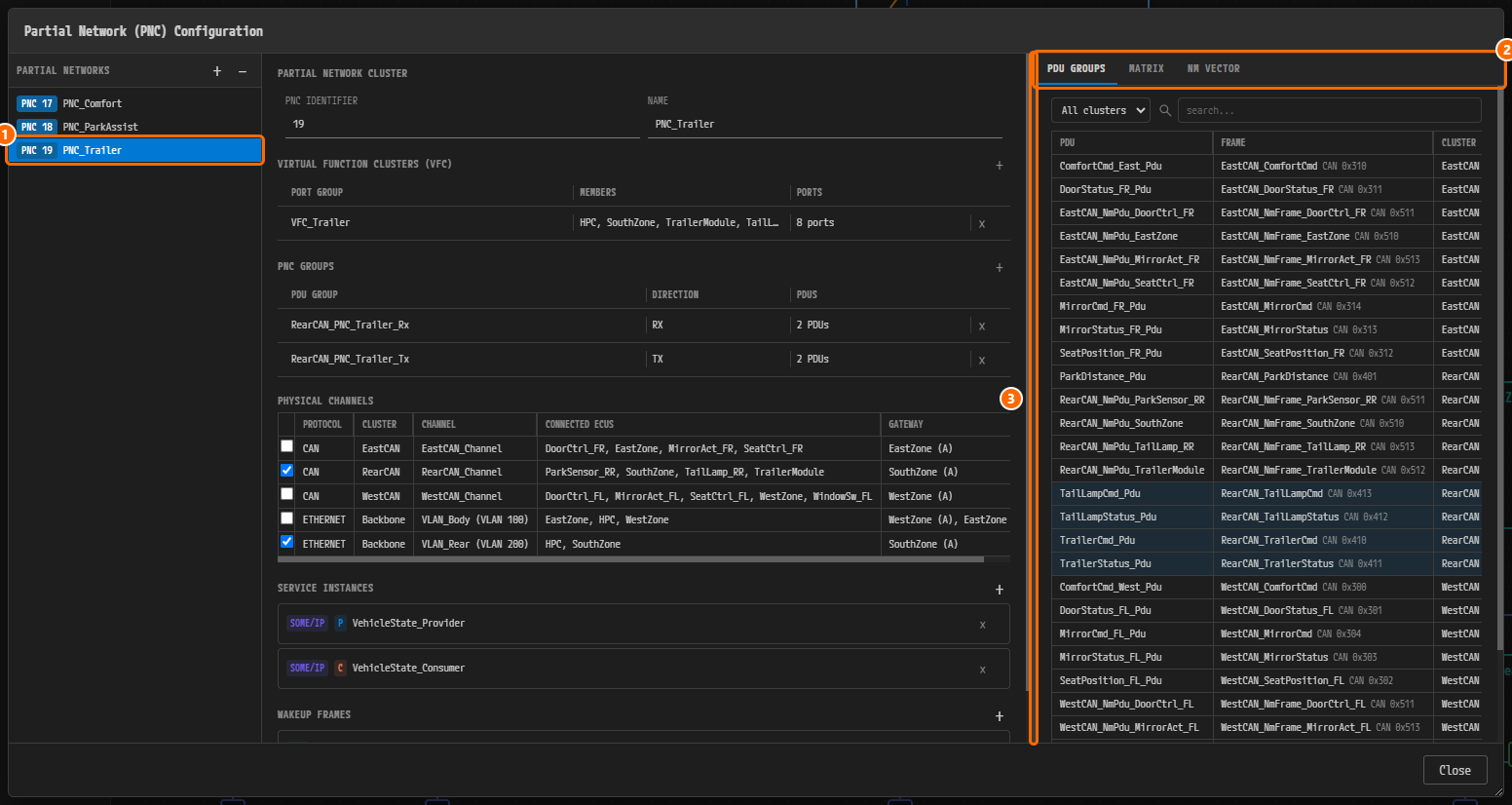
Figure 8-1. The dialog with PNC 19 PNC_Trailer selected. ① The list item PNC 19 PNC_Trailer. ② The viewer tab strip PDU GROUPS / MATRIX / NM VECTOR. The PDU GROUPS tab is selected at first. ③ The splitter between the detail area in the middle and the viewer. At the default width the CLUSTER column is cut off and the PNC MEMBERSHIP column is not visible.
-
Hover over the splitter (③ in Figure 8-1) and drag it about 340 px to the left to widen the viewer. All four columns — PDU, FRAME, CLUSTER and PNC MEMBERSHIP — should be visible.
Note. The widened width is kept when you switch tabs. Closing the dialog returns it to the default width.
Reading PDU GROUPS
The PDU GROUPS tab shows the PDUs of every cluster in one table. Each row is one PDU.
| Column | Contents |
|---|---|
| PDU | The PDU name |
| FRAME | The name of the frame that carries the PDU, the protocol and the CAN ID. For example, RearCAN_TrailerCmd CAN 0x410 |
| CLUSTER | The cluster name and protocol. For example, RearCAN CAN |
| PNC MEMBERSHIP | The PNC the PDU belongs to. If the PDU is contained in an I-PDU Group bound to a PNC, that PNC name appears. Otherwise "Assign PNCs..." appears dimmed. |
-
Check that the rows belonging to the PNC selected on the left (
PNC_Trailer) are highlighted in blue.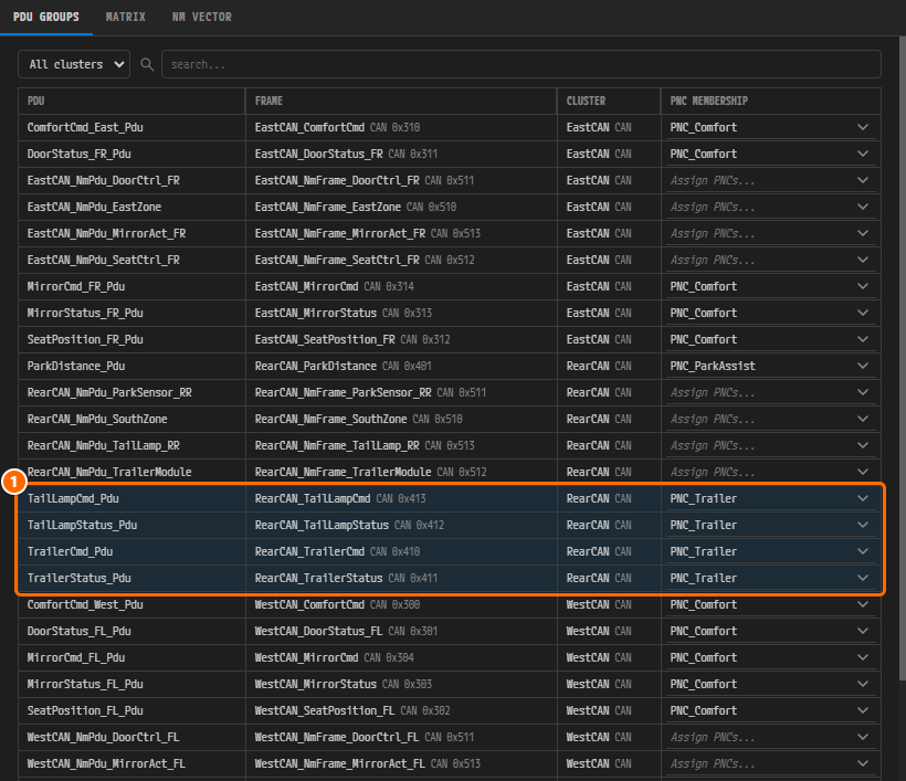
Figure 8-2. The PDU GROUPS table with the viewer widened. ① Four rows belonging to
PNC_Trailerare highlighted:TailLampCmd_Pdu(0x413),TailLampStatus_Pdu(0x412),TrailerCmd_Pdu(0x410),TrailerStatus_Pdu(0x411). All four havePNC_Trailerin the PNC MEMBERSHIP column.ComfortCmd_*,DoorStatus_*,MirrorCmd_*,MirrorStatus_*,SeatPosition_*andWindowSwitch_Pdubelong toPNC_Comfort, andParkDistance_Pdubelongs toPNC_ParkAssist.- The NM PDUs named
<cluster>_NmPdu_<ECU>are empty and show "Assign PNCs...". This is correct, because NM PDUs are not placed in the I-PDU Group of any PNC.
Note. Clicking a PNC MEMBERSHIP cell opens a checklist for assigning PNCs. For how to use it, see Checking PNC GROUPS. You do not click it in this chapter.
Note. The project you built yourself may show fewer frames and groups in this table than the example. For what differs and why, see Appendix — Differences Between Your Project and the Finished Example.
Narrowing by Cluster
-
Click the cluster filter at the top left of the viewer (initially All clusters) and choose RearCAN. The five choices are All clusters, Backbone, EastCAN, RearCAN and WestCAN.
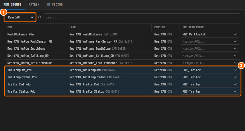
Figure 8-3. ① The cluster filter set to RearCAN. Only the nine PDU rows of RearCAN remain. ② The four rows belonging to
PNC_Trailer. Above them areParkDistance_Pdu(PNC_ParkAssist) and four NM PDU rows. -
Set the cluster filter back to All clusters.
Searching by Name
-
In the search field to the right of the cluster filter (placeholder
search...), typeTrailer.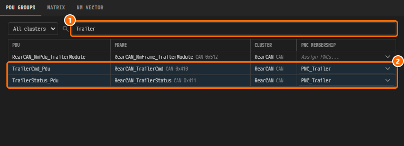
Figure 8-4. ①
Trailertyped in the search field. Three rows remain. ②TrailerCmd_PduandTrailerStatus_Pdu, which belong toPNC_Trailer. The first row,RearCAN_NmPdu_TrailerModule, is an NM PDU and so shows "Assign PNCs...".- The search looks in the PDU name, the frame name, the CAN ID and the protocol. It is case-insensitive. The
TailLamp*PDUs also belong toPNC_Trailer, but they do not appear because their names do not containTrailer. - The search does not look in cluster names. Use the cluster filter to narrow by cluster.
- The search looks in the PDU name, the frame name, the CAN ID and the protocol. It is case-insensitive. The
-
Clear the search field.
Reading MATRIX
The MATRIX tab shows the relationship between PNCs and physical channels in a single table. The rows are PNCs and the columns are physical channels.
-
Drag the splitter to the right to return the viewer to its original width. The PHYSICAL CHANNELS table in the middle becomes visible again. On the left, PNC 19 PNC_Trailer is still selected.
-
Click the MATRIX tab.
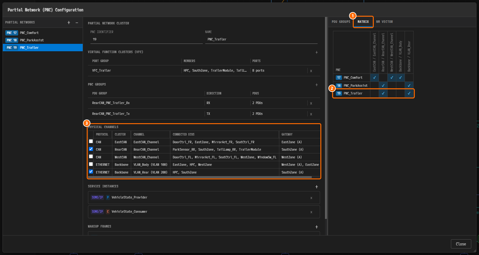
Figure 8-5. ① The MATRIX tab. ② The
PNC_Trailerrow of the matrix. TheRearCAN / RearCAN_ChannelandBackbone / VLAN_Rearcells carry a ✓. ③ PHYSICAL CHANNELS in the middle.RearCAN_ChannelandVLAN_Rear (VLAN 200)are checked. ② and ③ show the same values. -
Read the matrix.
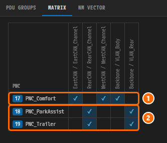
Figure 8-6. The MATRIX table enlarged. The column headers write "cluster / channel" vertically. A ✓ cell has a blue background. ① The
PNC_Comfortrow:EastCAN_Channel,WestCAN_Channel,VLAN_Body. ② ThePNC_ParkAssistandPNC_Trailerrows: bothRearCAN_ChannelandVLAN_Rear.PNC EastCAN / EastCAN_Channel RearCAN / RearCAN_Channel WestCAN / WestCAN_Channel Backbone / VLAN_Body Backbone / VLAN_Rear 17 PNC_Comfort✓ ✓ ✓ 18 PNC_ParkAssist✓ ✓ 19 PNC_Trailer✓ ✓ - For each PNC row, confirm that every channel the PNC has to cross carries a ✓. The values must match the PHYSICAL CHANNELS table you checked for each PNC in The PNC Dialog.
Caution. A matrix cell changes as soon as you click it. Clicking a cell turns on or off the same reference as the PHYSICAL CHANNELS check box in the middle (the physical channel reference of the SYSTEM model). You can correct the rows of every PNC on one screen, but this chapter only reads, so do not click. If you click by mistake, click the same cell again or press Ctrl+Z to undo. When there are unsaved changes, a ● marker appears in front of the dialog title.
Reading NM VECTOR
The NM VECTOR tab shows which byte and which bit of the NM PDU each PNC bit occupies. The PNC identifier is the absolute bit number inside the NM PDU. Identifier N sits at Byte N ÷ 8 quotient, bit N ÷ 8 remainder.
-
On the left, click PNC 17 PNC_Comfort.
-
Drag the splitter about 340 px to the left to widen the viewer again. At the default width the NM node table below scrolls horizontally.
-
Click the NM VECTOR tab.
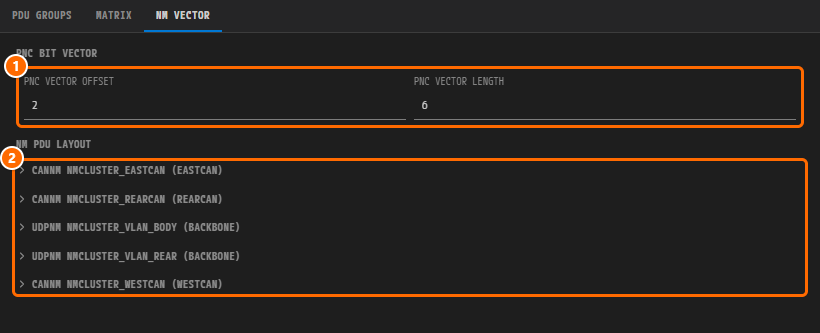
Figure 8-7. The NM VECTOR tab. ① PNC VECTOR OFFSET
2and PNC VECTOR LENGTH6in the PNC BIT VECTOR section. ② The five NM cluster headers in the NM PDU LAYOUT section. All of them are collapsed at first.- PNC VECTOR OFFSET and PNC VECTOR LENGTH exist once for the whole SYSTEM. They apply to every NM cluster alike. You entered the values under Setting the PNC Bit Vector. You do not change them in this chapter.
- An NM cluster header has the form
<NM kind> <NM cluster name> (<cluster>). The NM kind is eitherCanNmorUdpNm. On screen everything appears in upper case. For example,CanNm NmCluster_WestCAN (WestCAN)appears as CANNM NMCLUSTER_WESTCAN (WESTCAN). - The headers are sorted by NM cluster name (EastCAN, RearCAN, VLAN_Body, VLAN_Rear, WestCAN).
-
Click the bottom header, CANNM NMCLUSTER_WESTCAN (WESTCAN), to expand it.
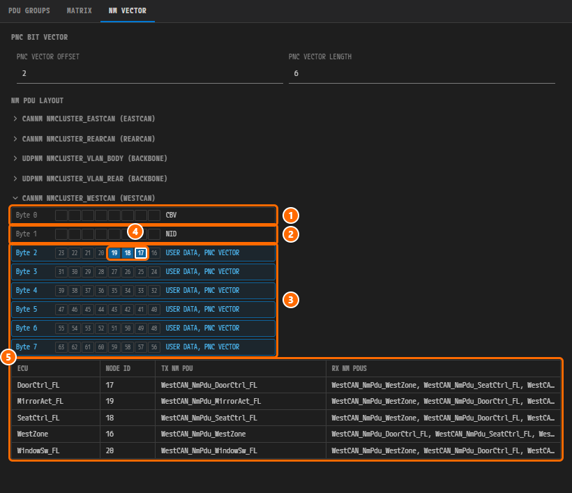
Figure 8-8.
NmCluster_WestCANexpanded. Each row is one byte of the NM PDU, and the eight cells are bits 7 down to 0 from left to right. ① Byte 0 = CBV (Control Bit Vector). ② Byte 1 = NID (Node ID). ③ Byte 2 to 7 = USER DATA, PNC VECTOR. Each cell carries a PNC identifier from 16 to 63. ④ The cells of the Byte 2 row read23 22 21 20 19 18 17 16from left to right, and among them the19,18and17cells are filled (the number badges sit above the frame so that they do not cover the cells). The cell of the selected PNC 17 has a white border. ⑤ The NM node table. -
Read the bit cells.
- The bit cells of defined PNCs are filled in blue. In this example they are 17, 18 and 19 in Byte 2.
- The cell of the PNC selected on the left gets a white border. When you select a different PNC, the border moves to the cell of that PNC.
- Hovering over a filled cell shows a tooltip with the PNC name and position. For example, "PNC_Comfort (byte 2, bit 1)" and "PNC_Trailer (byte 2, bit 3)". On an empty cell only the number and the position appear, as in "PNC 20 (byte 2, bit 4)".
- Byte 2 to 7 carry both labels, USER DATA and PNC VECTOR, because in this example the NM user data area (offset 2, length 6) and the PNC vector (offset 2, length 6) use the same bytes.
-
Read the NM node table (⑤ in Figure 8-8).
Column Contents ECU The ECUs that participate in this NM cluster, sorted by name. NODE ID The NM node ID. This is the value that goes into Byte 1 (NID) of the NM PDU. TX NM PDU The NM PDU this ECU sends RX NM PDUS The NM PDUs this ECU receives. These are all the NM PDUs sent by the other nodes of the same cluster. The values for
NmCluster_WestCANare as follows.ECU NODE ID TX NM PDU DoorCtrl_FL17 WestCAN_NmPdu_DoorCtrl_FLMirrorAct_FL19 WestCAN_NmPdu_MirrorAct_FLSeatCtrl_FL18 WestCAN_NmPdu_SeatCtrl_FLWestZone16 WestCAN_NmPdu_WestZoneWindowSw_FL20 WestCAN_NmPdu_WindowSw_FLNote. The RX NM PDUS cell is still cut off at the end (…) even with the viewer widened. Hover over the cell to see the full value in a tooltip.
-
Expand the other NM clusters the same way. All five clusters have the same layout: Byte 0 = CBV, Byte 1 = NID, Byte 2 to 7 = PNC vector.
The ECUs below are listed in NODE ID order. The node table on screen is sorted by ECU name.
NM cluster ECU (NODE ID) NmCluster_EastCAN(EastCAN)EastZone(16),DoorCtrl_FR(17),SeatCtrl_FR(18),MirrorAct_FR(19)NmCluster_RearCAN(RearCAN)SouthZone(16),ParkSensor_RR(17),TrailerModule(18),TailLamp_RR(19)NmCluster_VLAN_Body(Backbone)HPC(0),WestZone(1),EastZone(2),SouthZone(3),HPC(4)NmCluster_VLAN_Rear(Backbone)HPC(0),SouthZone(1),WestZone(2),EastZone(3),HPC(4)Note. Both UdpNm clusters belong to the communication cluster
Backbone, so their node tables list one NM node for every connector attached toBackbone, whichever VLAN the connector uses. The nodes of the other VLAN's connectors have empty TX NM PDU and RX NM PDUS cells:SouthZone(3) andHPC(4) onNmCluster_VLAN_Body, andWestZone(2),EastZone(3) andHPC(4) onNmCluster_VLAN_Rear.HPChas one connector on each VLAN, so it appears twice on both clusters. -
When you have seen everything, click Close at the bottom right of the dialog. Because you only read, it closes without asking whether to save.
How Filter Masks Relate to NM VECTOR
The PNC FILTER ARRAY MASKS value you entered on the connector under Calculating the Filter Mask is the array that holds only the PNC vector part (Byte 2 to 7) of the NM PDU. Byte 0 of the mask array is therefore Byte 2 of the NM PDU.
byteIndex = quotient of pncId ÷ 8 − pncVectorOffset    # the byte in the mask array
bit       = remainder of pncId ÷ 8                     # the bit within that byte
value     = 2 ^ bit
| PNC | Position in the NM PDU (tooltip) | Position in the mask array | Value |
|---|---|---|---|
17 PNC_Comfort | byte 2, bit 1 | Byte 0, bit 1 (17 ÷ 8 = 2, 2 − 2 = 0) | 0x02 |
18 PNC_ParkAssist | byte 2, bit 2 | Byte 0, bit 2 | 0x04 |
19 PNC_Trailer | byte 2, bit 3 | Byte 0, bit 3 | 0x08 |
- The mask of a connector that passes only PNC 17 (for example
WestZone_CanFd_Conn) is02 00 00 00 00 00. That is the value with only cell 17 of Byte 2 set in Figure 8-8. - A connector that passes PNC 18 and 19 (for example
SouthZone_CanFd_Conn) ORs the values of the same byte together:0x04|0x08=0x0C, that is0C 00 00 00 00 00. - The length of the mask array must equal PNC VECTOR LENGTH (
pncVectorLength, 6) (constr_3686). The grid title PNC FILTER ARRAY MASKS (6/6) in the connector properties shows this length.
Caution. The "byte 2" in the tooltip is a byte number relative to the NM PDU, while the "Byte 0" in the mask grid is a byte number relative to the vector. The two numbers differ by PNC VECTOR OFFSET (2).
Why Is It Designed This Way?
- The three tabs view the same design from different directions. PDU GROUPS looks from the PDU to the PNC, MATRIX from the PNC to the channel, and NM VECTOR from the PNC to the NM PDU bit. What is missing in one tab shows up in another.
- Physical channels are decided by a person. Which channels a PNC spans is not derived automatically from groups or PDUs. A matrix cell and a PHYSICAL CHANNELS check box are two entry points for changing the same reference.
- The PNC identifier is a bit number in the NM PDU. Once you fix the identifier, the position inside the NM PDU and the filter mask value are fixed with it. NM VECTOR is where you confirm that position visually.
Check Your Work
- In the PDU GROUPS tab, selecting
PNC_Trailerhighlights the four rowsTailLampCmd_Pdu,TailLampStatus_Pdu,TrailerCmd_PduandTrailerStatus_Pdu, and their PNC MEMBERSHIP column readsPNC_Trailer. - Setting the cluster filter to RearCAN leaves nine rows.
- In the MATRIX tab,
PNC_Comfortcarries a ✓ forEastCAN_Channel,WestCAN_ChannelandVLAN_Body, andPNC_ParkAssistandPNC_Trailercarry a ✓ forRearCAN_ChannelandVLAN_Rear. - In the NM VECTOR tab, PNC VECTOR OFFSET is
2and PNC VECTOR LENGTH is6. - Expanding
NmCluster_WestCANshows the cells 17, 18 and 19 of Byte 2 filled. - Clicking Close does not ask whether to save. The dialog title carried no ● marker.
Next Steps
In AP Machines — NM Handles and FunctionGroup you configure NM handles and FunctionGroups on the HPC machine.