PNC Dialog: Per-PNC Bindings
What You Will Do
In this chapter you bind the references that each PNC (Partial Network Cluster) needs, using the PNC dialog. One screen ties a VFC (Virtual Function Cluster), I-PDU groups, physical channels, service instances and wakeup frames to a single PNC.
You follow each section with PNC_ParkAssist as the example. Wakeup frames are entered on PNC_Trailer. The remaining values for PNC_Comfort and PNC_Trailer are given as a value table and as finished screenshots.
When you finish this chapter, the model is in the following state.
PNC_ParkAssisthasVFC_ParkAssist, the groupsRearCAN_PNC_ParkAssist_Rx/_Tx, the channelsRearCAN_ChannelandVLAN_Rear, and the service instancesParkDistance_ProviderandParkDistance_Consumerbound to it.- The WAKEUP FRAMES of
PNC_TrailercontainsRearCAN_NmFrame_TrailerModule. - The changes are saved.
Before You Begin
- Finish VFB and VFC (PortGroup) first.
- This chapter continues from the previous one. Every result up to that point must already be in the model, so the starting state is as follows.
- Three PNCs exist:
PNC_Comfort17,PNC_ParkAssist18 andPNC_Trailer19 (see PNC Definitions and Connector PNC Properties). - Eight I-PDU groups exist in the SIGNAL model, and each was bound to its PNC when you created it in Chapter 4 (see Signals, PDUs, Frames and I-PDU Groups).
PNC_ParkAssistholdsRearCAN_PNC_ParkAssist_Rx(one PDU,ParkDistance_Pdu) andRearCAN_PNC_ParkAssist_Tx(no PDUs). - Seven SOME/IP service instances are bound to connectors (see Interfaces and SOME/IP Services).
- The atomic SWCs have the PortGroups
VFC_Comfort,VFC_ParkAssistandVFC_Trailer, and PortGroups of the same names were created automatically on the compositions and on the root. None of them is bound to a PNC yet (see VFB and VFC (PortGroup)). - The PortGroup member ports (OUTER PORTS) of the compositions and of the application AAs are still empty. You fill them from SWC HIERARCHY in this chapter.
- Three PNCs exist:
- Figures 7-2 through 7-9, 7-14 and 7-15 in this chapter were captured with nothing bound to the PNC. In a project where you followed Chapter 4, PNC GROUPS already shows two group rows. Each section points out where your screen differs.
The values you enter on PNC_ParkAssist in this chapter are as follows.
| Section | Value |
|---|---|
| VIRTUAL FUNCTION CLUSTERS (VFC) | VFC_ParkAssist |
| PNC GROUPS | RearCAN_PNC_ParkAssist_Rx (ParkDistance_Pdu), RearCAN_PNC_ParkAssist_Tx (no PDUs) |
| PHYSICAL CHANNELS | CAN RearCAN / RearCAN_Channel, ETHERNET Backbone / VLAN_Rear (VLAN 200) |
| SERVICE INSTANCES | ParkDistance_Provider, ParkDistance_Consumer |
| WAKEUP FRAMES | None |
Opening the PNC Dialog
-
In the EDITOR view on the left, click System under DESIGN to open the System editor (tab
PNC:System). -
In the vertical icon strip along the left edge of the canvas, click the second (lower) icon. Hovering over it shows the tooltip Partial Network (PNC).
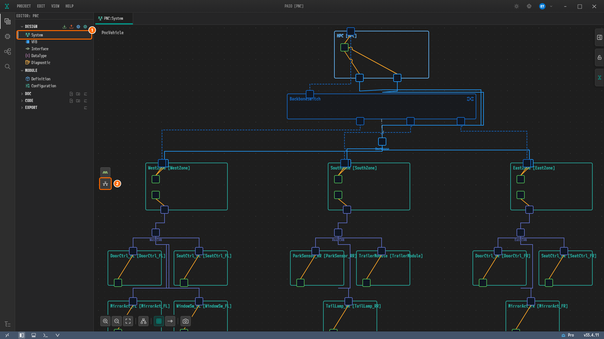
Figure 7-1. The System editor. ① System under DESIGN in the EDITOR view. ② The PNC button, the second (lower) icon in the vertical icon strip along the left edge of the canvas.
The Partial Network (PNC) Configuration dialog opens.
-
In the PARTIAL NETWORKS list on the left, click PNC 18 PNC_ParkAssist.
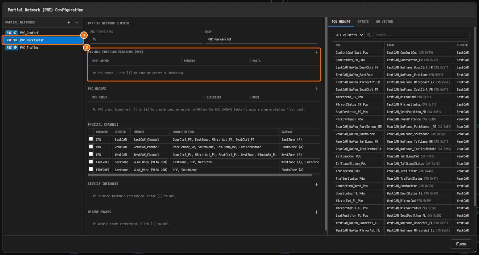
Figure 7-2. The screen with PNC 18 PNC_ParkAssist selected. ① The list item PNC 18 PNC_ParkAssist. ② The VIRTUAL FUNCTION CLUSTERS (VFC) section, which still shows "No VFC bound. Click [+] to bind or create a PortGroup." PNC GROUPS, SERVICE INSTANCES and WAKEUP FRAMES are empty as well, and nothing is checked in PHYSICAL CHANNELS.
Screen Layout
The dialog is divided into three areas.
| Area | Contents |
|---|---|
| PARTIAL NETWORKS, left | The PNC list. Each item has the form PNC <identifier> <name>. The +/− buttons in the header add and delete PNCs (see PNC Definitions and Connector PNC Properties). |
| Detail, center | The sections of the selected PNC, from top to bottom: PARTIAL NETWORK CLUSTER (PNC IDENTIFIER, NAME) → VIRTUAL FUNCTION CLUSTERS (VFC) → PNC GROUPS → PHYSICAL CHANNELS → SERVICE INSTANCES → WAKEUP FRAMES. The + button to the right of each section header adds an entry. When the contents grow long, scroll the center detail vertically. |
| Viewer, right | The PDU GROUPS, MATRIX and NM VECTOR tabs. This chapter uses only the PDU GROUPS tab. The other tabs are covered in Reviewing PDU GROUPS, MATRIX and NM VECTOR. |
- When there are unsaved changes, a ● marker appears before the dialog title.
- Save with Ctrl+S. The only button at the bottom of the dialog is Close.
Binding a VFC
-
Click the + button to the right of the VIRTUAL FUNCTION CLUSTERS (VFC) header (tooltip Bind or create a VFC (PortGroup)).
A menu opens. The New VFC (PortGroup)... item at the top creates a new PortGroup, and the entries below the separator are the VFCs that already exist.
-
In the menu, click VFC_ParkAssist.
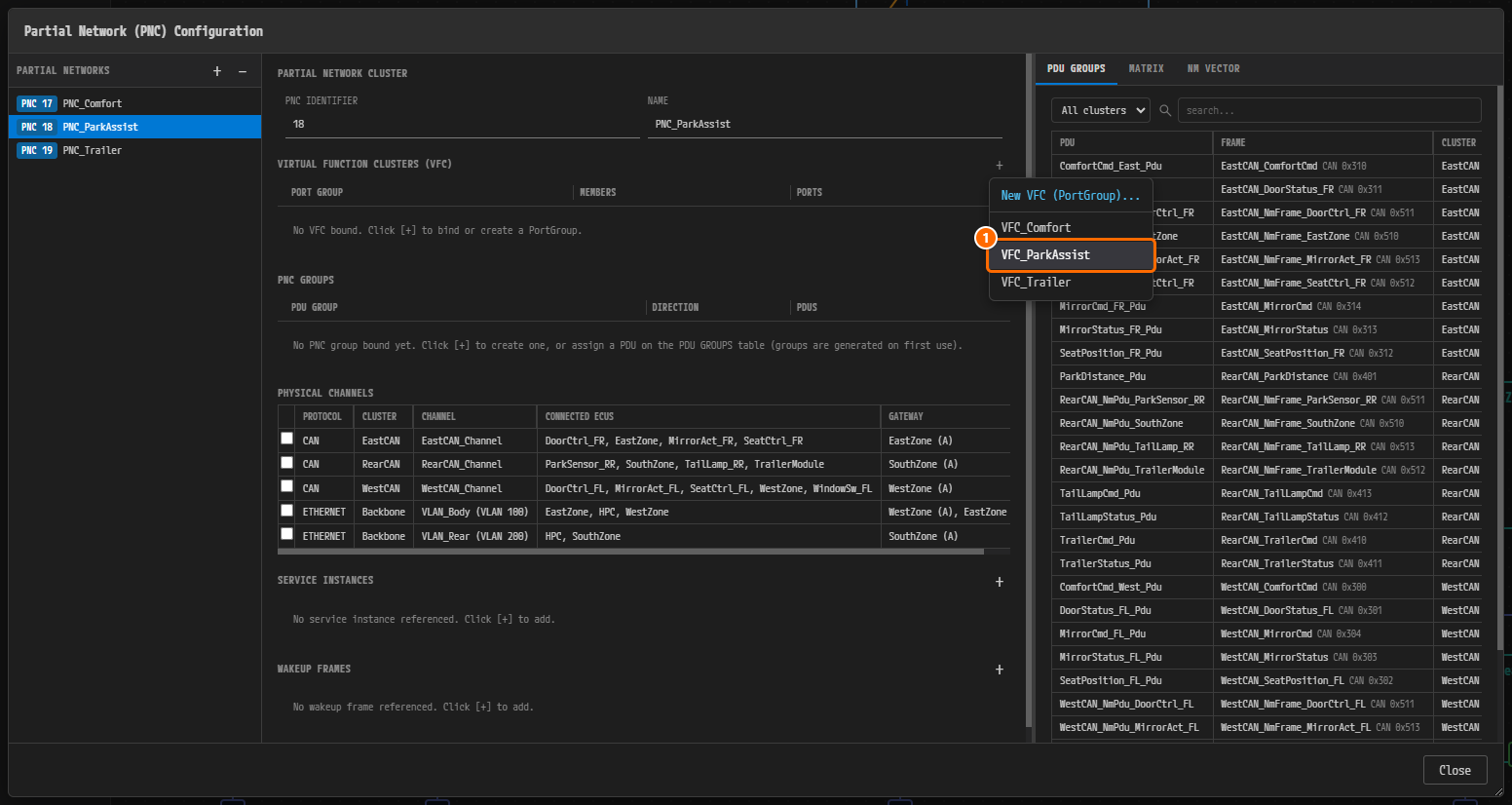
Figure 7-3. The + menu. Below New VFC (PortGroup)... are
VFC_Comfort,VFC_ParkAssistandVFC_Trailer. ① The item to choose,VFC_ParkAssist.A row appears in the VFC table, and a ● marker appears before the title.
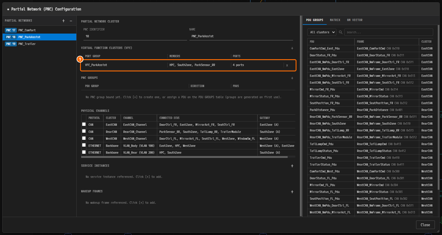
Figure 7-4. ① The new row: PORT GROUP
VFC_ParkAssist, MEMBERSHPC, SouthZone, ParkSensor_RR, PORTS4 ports.Note. MEMBERS lists the direct prototypes of the root composition
PncVehiclethat have a PortGroup of the same name (VFC_ParkAssist). A prototype with a different name does not count as a member (see VFC family rules). -
Click the
VFC_ParkAssistrow to expand it.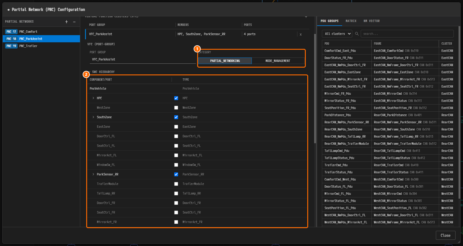
Figure 7-5. The VFC (PORT-GROUP) area of the expanded row. ① CATEGORY, with PARTIAL_NETWORKING selected. ② The SWC HIERARCHY table (columns COMPONENT/PORT, a checkbox and TYPE). All 14 direct prototypes under the root
PncVehicleare listed, and once you finish checking, only the three rowsHPC,SouthZoneandParkSensor_RRare checked. -
In SWC HIERARCHY, check the compositions and ports that take part in this VFC. For
VFC_ParkAssistthese are the three compositionsHPC,SouthZoneandParkSensor_RR. Check the composition row, then expand it and check, in the port rows, the OUTER PORTS listed in the ECU composition table of VFB and VFC (PortGroup).Composition Ports to check HPCParkDistanceSvcSouthZoneParkDistance,ParkDistanceSvcParkSensor_RRParkDistanceCheck the ports of the application AA
ParkAssistAppinsideHPC(ParkDistanceSvc,VehicleStateSvc) the same way. An AA has no dedicated screen for creating a PortGroup, so this table is the only place where you create the PortGroup of an AA. -
Click the row again to collapse it.
Caution. A checkbox in SWC HIERARCHY is written to the SWC model (
.swc.io.model) the moment you click it. It does not wait for Ctrl+S. Checking a composition row creates or deletes a PortGroup of the same name on that composition type, and checking a port row in the expanded view adds or removes a member port of that PortGroup. Clearing a check by mistake deletes the PortGroup of that composition, so do not touch rows that are not in the table.
Note. The × at the right of a VFC row (tooltip Unbind VFC from this PNC (the PortGroup itself is kept)) only breaks the link to the PNC. The PortGroup itself remains.
Checking PNC GROUPS
PNC GROUPS lists the I-PDU groups bound to this PNC. You created the groups with the + button of PNC GROUPS in Signals, PDUs, Frames and I-PDU Groups, and a group created with + is bound immediately to the PNC that was selected at the time. PNC_ParkAssist therefore already has two rows.
Confirm that PNC GROUPS contains RearCAN_PNC_ParkAssist_Rx (RX, 1 PDU) and RearCAN_PNC_ParkAssist_Tx (TX, 0 PDUs). The result matches PNC GROUPS in Figure 7-10.
The rest of this section shows the second way to bind a group: assigning a PNC to a PDU in the PDU GROUPS table on the right. Use it for a PDU that does not belong to any PNC yet. In this example you already did this in Chapter 4, so read along and only compare the screens.
The + button of PNC GROUPS (tooltip Add I-PDU group to this PNC) opens only a menu for creating a new group (New Rx group..., New Tx group...). Entering the name of a group that already exists is rejected with "A group with this name already exists". To add a PDU to an existing group, therefore, use the PDU GROUPS table on the right. When a PNC has no Rx group and no Tx group at all and you assign one PDU to that PNC, a <cluster>_<PNC>_Rx/_Tx pair is created and bound to the PNC. If a group of the same name already exists, that group is used instead of a new one.
Note. Figures 7-6 through 7-9 were captured while the groups were not yet bound. If you followed Chapter 4, the PNC MEMBERSHIP cell in Figure 7-6 already shows
PNC_ParkAssistinstead of "Assign PNCs...", andRearCAN_PNC_ParkAssist_Txin Figure 7-9 has an empty CONTAINED PDUS. Steps 3 and 7 below are therefore already in effect; do not repeat them.
-
In the search field of the PDU GROUPS tab on the right, type
ParkDistance. Only the single rowParkDistance_Pduremains in the table. -
Drag the divider between the center detail and the viewer on the right to the left to widen the viewer. At the default width the PNC MEMBERSHIP column is cut off at the right edge, and the dropdown arrow of its cell is hidden.
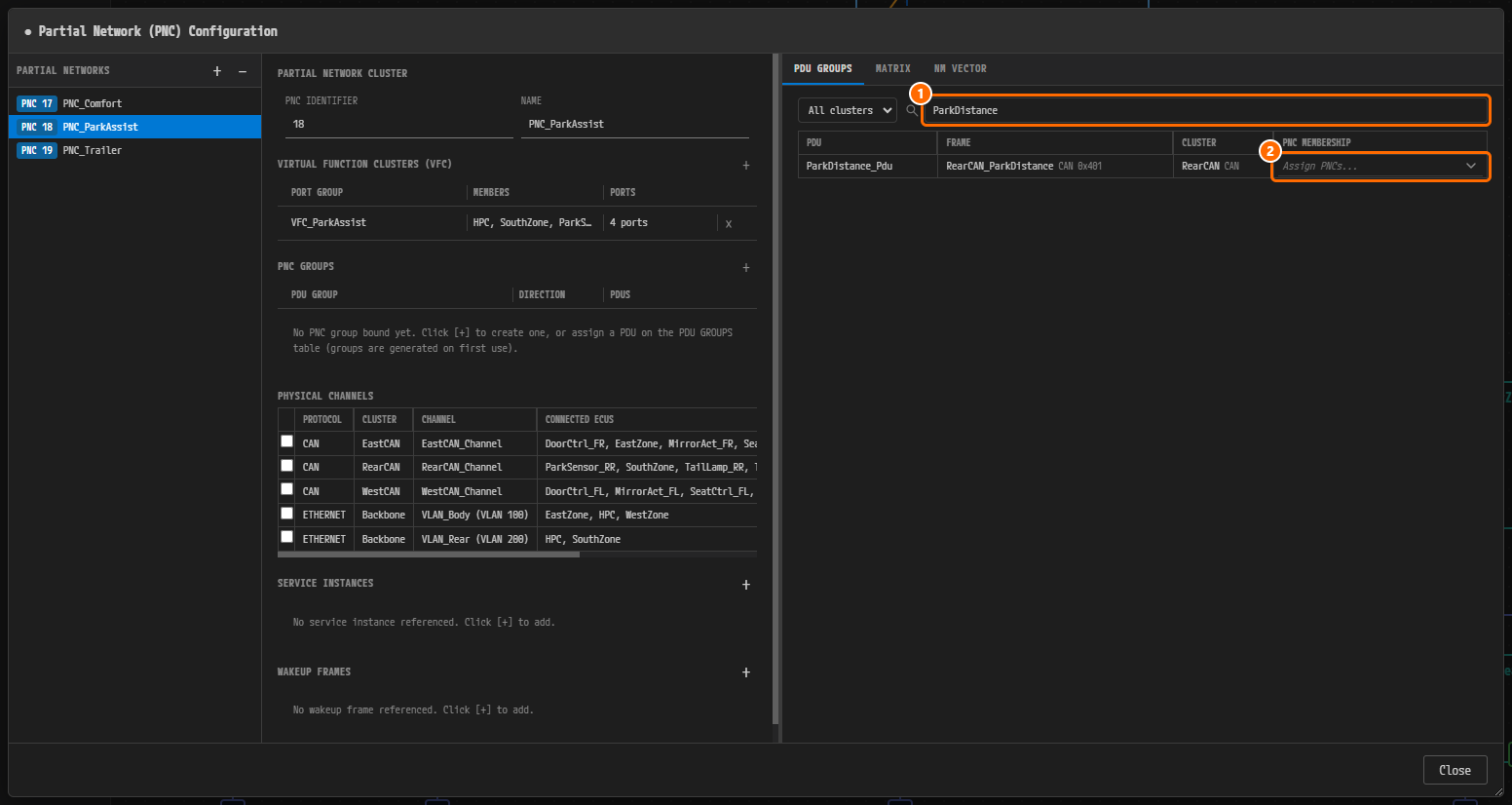
Figure 7-6. The PDU GROUPS table with the viewer widened. ①
ParkDistancetyped in the search field. The remaining row isParkDistance_Pdu/RearCAN_ParkDistance CAN 0x401/RearCAN CAN. ② The PNC MEMBERSHIP cell ("Assign PNCs..."). -
Click the PNC MEMBERSHIP cell. A checklist opens; check PNC_ParkAssist.
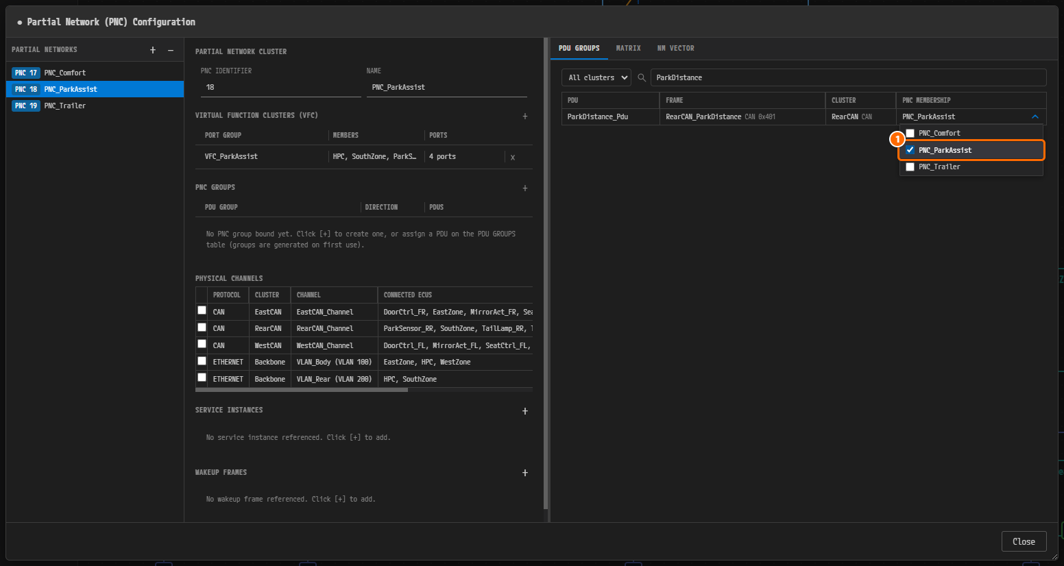
Figure 7-7. The PNC MEMBERSHIP checklist (
PNC_Comfort,PNC_ParkAssist,PNC_Trailer). ①PNC_ParkAssistchecked. -
Press Esc to close the checklist. The dialog stays open. The assignment takes effect when the checklist closes.
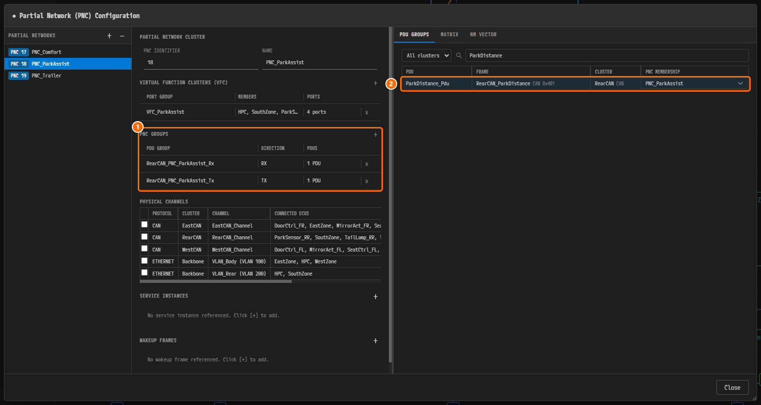
Figure 7-8. ①
RearCAN_PNC_ParkAssist_Rx(RX,1 PDU) andRearCAN_PNC_ParkAssist_Tx(TX,1 PDU) are bound in PNC GROUPS. ② TheParkDistance_Pdurow is highlighted, and PNC MEMBERSHIP showsPNC_ParkAssist.In Figure 7-8 the Tx group also holds
1 PDU. When you assign a PDU to a PNC, the PDU enters both the Rx group and the Tx group if it has both a sending node and a receiving node. A bus PDU usually has both, so it enters both groups. Group direction is seen from the Zone (gateway) point of view, andParkDistance_Pduis a PDU thatSouthZonereceives, so this example keeps it in the Rx group only (see Naming conventions). The next step removesParkDistance_Pdufrom the Tx group. -
Drag the viewer divider back to the right to restore the original width.
-
In PNC GROUPS, click the
RearCAN_PNC_ParkAssist_Txrow to expand it. The GROUP area (PDU GROUP, DIRECTION) and the CONTAINED PDUS table appear. -
At the far right of the
ParkDistance_Pdurow in CONTAINED PDUS, click the × (tooltip Remove contained element).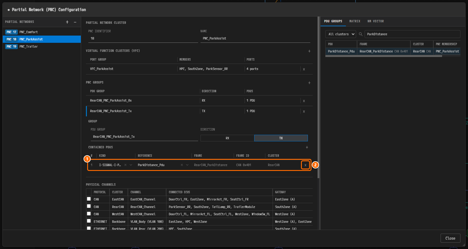
Figure 7-9. The expanded
RearCAN_PNC_ParkAssist_Tx. DIRECTION is TX. ① TheParkDistance_Pdurow in CONTAINED PDUS (RearCAN_ParkDistance,CAN 0x401,RearCAN). ② The × button to click.The PDUS value of the Tx group row changes to
0 PDUs. -
Click the
RearCAN_PNC_ParkAssist_Txrow again to collapse it. -
Clear the search field of the PDU GROUPS tab.
Caution. Do not confuse the × button on a CONTAINED PDUS row with the × button at the far right of the group row (the
RearCAN_PNC_ParkAssist_Txrow). The × on the group row (tooltip Delete group (removes it from the SIGNAL model and every reference)) does not just break the binding; it deletes the group itself.
Selecting Physical Channels
The PHYSICAL CHANNELS table lists every physical channel in the project. The columns are a checkbox, PROTOCOL, CLUSTER, CHANNEL, CONNECTED ECUS and GATEWAY.
-
Select the checkboxes of the following two rows.
- CAN /
RearCAN/RearCAN_Channel - ETHERNET /
Backbone/VLAN_Rear (VLAN 200)
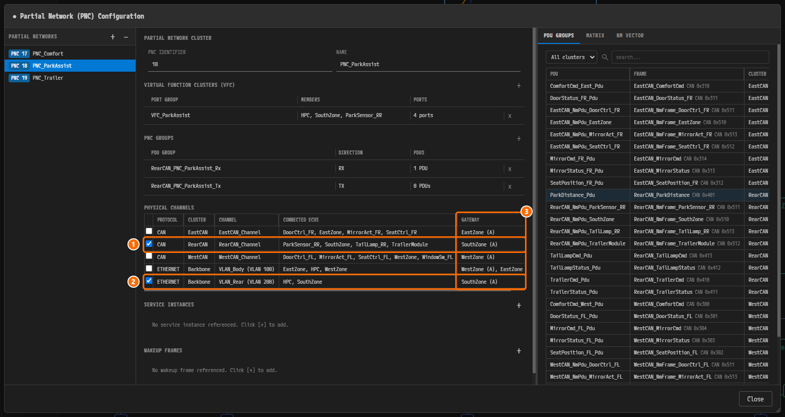
Figure 7-10. ① The
RearCAN_Channelrow checked. ② TheVLAN_Rear (VLAN 200)row checked. ③ The GATEWAY column, which readsSouthZone (A)for both channels. The Tx group in PNC GROUPS holds0 PDUs. - CAN /
Note. The GATEWAY column is display only. It shows the node that acts as the PNC gateway on each channel, where
(A)means ACTIVE and(P)means PASSIVE. The values come from the PNC properties of the connector (see PNC Definitions and Connector PNC Properties). At the default width, a long value is truncated, as inWestZone (A), EastZone (P)on theVLAN_Bodyrow. Hover over the cell to see the full value in a tooltip.
Caution. Physical channels are not filled in automatically. Binding a group or a PDU does not change the channel checks. You check the channels a PNC spans yourself.
Adding Service Instances
-
Click the + to the right of the SERVICE INSTANCES header (tooltip Add service instance reference). A candidate list with a search field opens. Each candidate shows its role and node in small text below the name, for example
SOME/IP provider on SouthZone. -
Type
ParkDistancein the search field. The seven candidates narrow to two. -
Click ParkDistance_Provider.
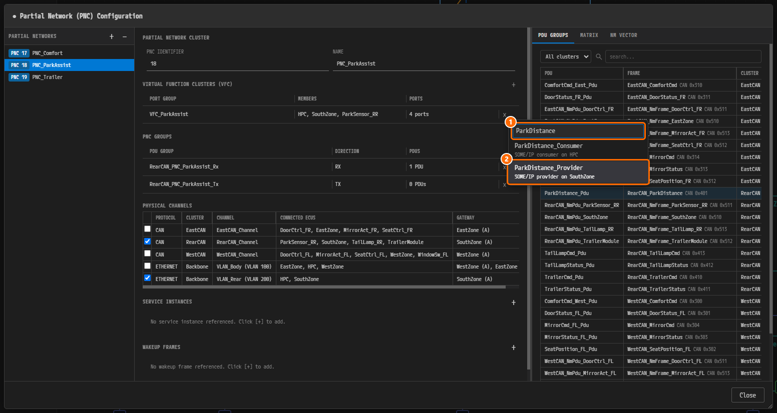
Figure 7-11. The candidate list of SERVICE INSTANCES. ①
ParkDistancetyped in the search field. ② The item to choose,ParkDistance_Provider(SOME/IP provider on SouthZone). Above it,ParkDistance_ConsumerreadsSOME/IP consumer on HPC. -
Click the + button again, type
ParkDistance, and click ParkDistance_Consumer.Two cards appear. Each card shows a SOME/IP badge, a role badge (P for provider, C for consumer) and the instance name.
-
(Check only) Click the
ParkDistance_Providercard to expand its details.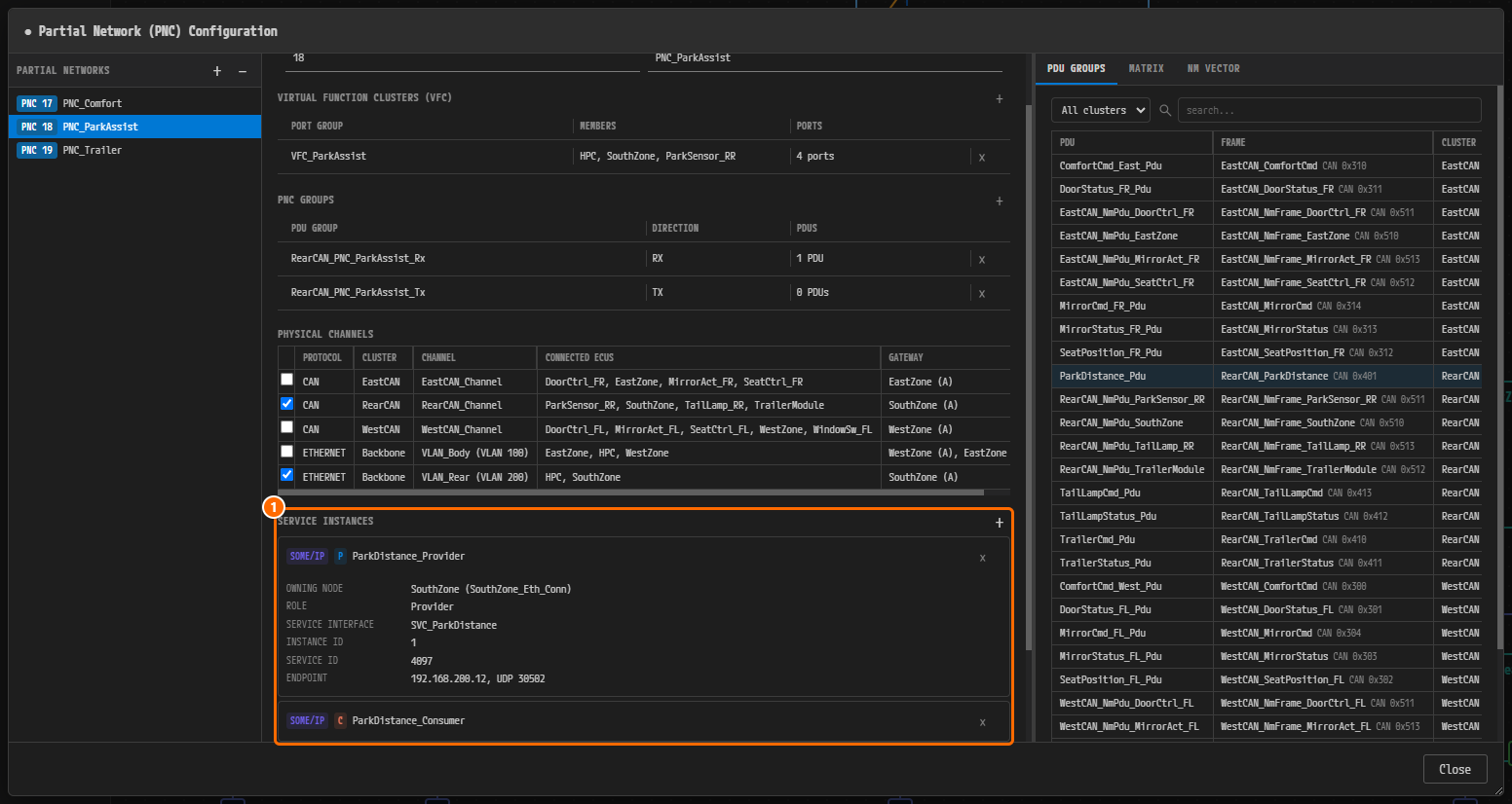
Figure 7-12. ① The SERVICE INSTANCES section. The expanded
ParkDistance_Providercard shows OWNING NODESouthZone (SouthZone_Eth_Conn), ROLEProvider, SERVICE INTERFACESVC_ParkDistance, INSTANCE ID1, SERVICE ID4097and ENDPOINT192.168.200.12, UDP 30502. Below it is theParkDistance_Consumercard.
Note. The × at the right of a card (tooltip Remove reference) deletes only the reference from the PNC. The service instance itself remains.
Saving
-
Press Ctrl+S.
The ● marker before the title disappears.
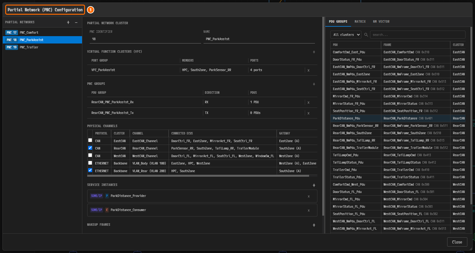
Figure 7-13. PNC 18 PNC_ParkAssist after saving. ① The dialog title, with no ● marker in front of it. One VFC, two groups (RX
1 PDU, TX0 PDUs), two channels and two service instances are bound, and WAKEUP FRAMES at the bottom has no cards.
Note. When you save from the dialog, the PNC bindings are written to the SYSTEM model (
SYSTEM.io.model) and the group contents to the SIGNAL model (SIGNAL.io.model). The System editor tab (PNC:System) does not change. If you click Close without saving, a prompt asks whether to save.
Adding Wakeup Frames
PNC_ParkAssist has no wakeup frame. You enter wakeup frames on PNC_Trailer.
-
In the list on the left, click PNC 19 PNC_Trailer.
-
Click the + to the right of the WAKEUP FRAMES header (tooltip Add wakeup frame reference). The 29 CAN frames appear as candidates. Each candidate shows its CAN ID and its cluster and channel below the name.
-
Type
TrailerModulein the search field. The 29 candidates narrow to one. -
Click RearCAN_NmFrame_TrailerModule.
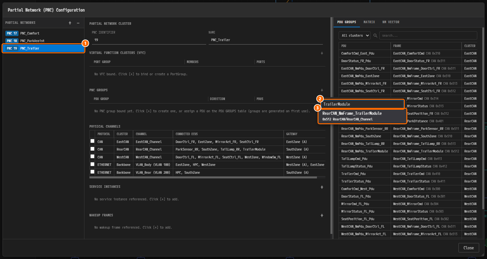
Figure 7-14. ① PNC 19 PNC_Trailer. ②
TrailerModuletyped in the search field. ③ The item to choose,RearCAN_NmFrame_TrailerModule(0x512 RearCAN/RearCAN_Channel).A card with a CAN badge appears.
-
(Check only) Click the card to expand its details.
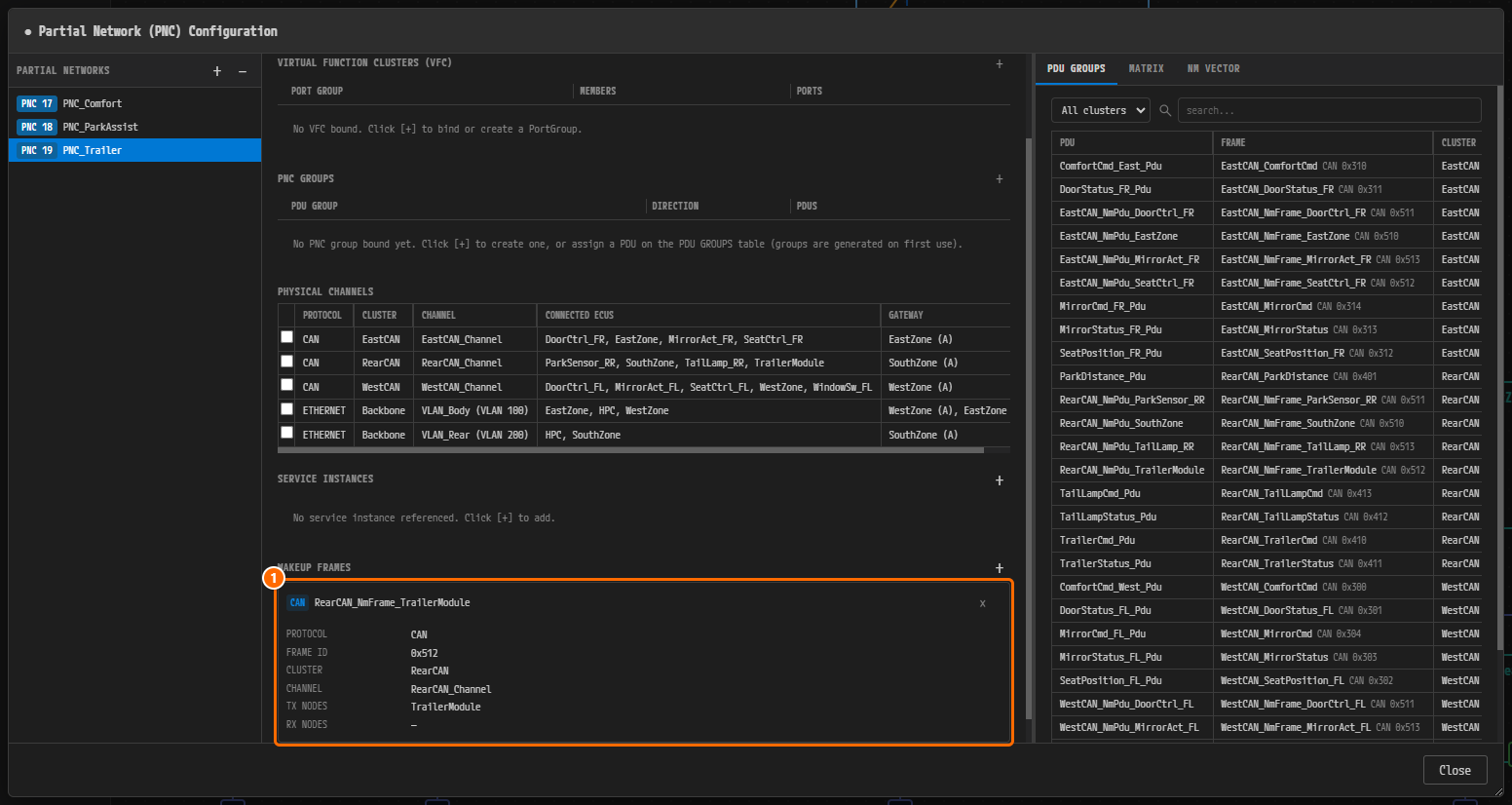
Figure 7-15. ① The expanded
RearCAN_NmFrame_TrailerModulecard, showing PROTOCOLCAN, FRAME ID0x512, CLUSTERRearCAN, CHANNELRearCAN_Channel, TX NODESTrailerModuleand RX NODES—. -
Press Ctrl+S to save.
-
Click Close to close the dialog. Because you saved first, it closes without a prompt.
Note. When an Rx group is bound to the PNC, the frames that carry the PDUs of that group appear first at the top of the candidate list, under a PNC RX FRAMES header.
PNC_Trailerin Figure 7-14 has no group bound, so all 29 frames appear as one list. If you followed Chapter 4,RearCAN_PNC_Trailer_Rxis already bound, so your list starts with that header and the frames of its PDUs.
Values for the Remaining PNCs
Enter the values for PNC_Comfort and PNC_Trailer the same way. The next chapter starts from a state in which all three PNCs are fully bound.
The PNC GROUPS column holds the values that were already bound when you created the groups in Chapter 4, so only confirm them. The four things you enter here are VFC, PHYSICAL CHANNELS, SERVICE INSTANCES and WAKEUP FRAMES. After binding a VFC, expand its row and check, in SWC HIERARCHY, the compositions listed in the MEMBERS table below and their ports.
| PNC | VFC | PNC GROUPS | PHYSICAL CHANNELS | SERVICE INSTANCES | WAKEUP FRAMES |
|---|---|---|---|---|---|
PNC 17 PNC_Comfort | VFC_Comfort | WestCAN_PNC_Comfort_Rx, WestCAN_PNC_Comfort_Tx, EastCAN_PNC_Comfort_Rx, EastCAN_PNC_Comfort_Tx | EastCAN_Channel, WestCAN_Channel, VLAN_Body (VLAN 100) | ComfortControl_Provider_West (P), ComfortControl_Provider_East (P), ComfortControl_Consumer (C) | WestCAN_NmFrame_DoorCtrl_FL (0x511), EastCAN_NmFrame_DoorCtrl_FR (0x511) |
PNC 18 PNC_ParkAssist | VFC_ParkAssist | RearCAN_PNC_ParkAssist_Rx, RearCAN_PNC_ParkAssist_Tx | RearCAN_Channel, VLAN_Rear (VLAN 200) | ParkDistance_Provider (P), ParkDistance_Consumer (C) | None |
PNC 19 PNC_Trailer | VFC_Trailer | RearCAN_PNC_Trailer_Rx, RearCAN_PNC_Trailer_Tx | RearCAN_Channel, VLAN_Rear (VLAN 200) | VehicleState_Provider (P), VehicleState_Consumer (C) | RearCAN_NmFrame_TrailerModule (0x512) |
The CONTAINED PDUS of each group match the group table in Signals, PDUs, Frames and I-PDU Groups. The members and the PORTS value of each VFC are as follows.
| VFC | MEMBERS (direct prototypes checked in SWC HIERARCHY) | PORTS |
|---|---|---|
VFC_Comfort | HPC, WestZone, EastZone, DoorCtrl_FL, SeatCtrl_FL, MirrorAct_FL, WindowSw_FL, DoorCtrl_FR, SeatCtrl_FR, MirrorAct_FR (10) | 28 ports |
VFC_ParkAssist | HPC, SouthZone, ParkSensor_RR (3) | 4 ports |
VFC_Trailer | HPC, SouthZone, TrailerModule, TailLamp_RR (4) | 8 ports |
Note. To create the groups of
PNC_Trailerfrom the PDU GROUPS table instead of creating them directly (that is, if you skipped Chapter 4), assign PNC_Trailer to each of the four PDUsTrailerStatus_Pdu,TailLampStatus_Pdu,TrailerCmd_PduandTailLampCmd_Pdu. Each PDU enters both the Rx group and the Tx group, so use the × button in CONTAINED PDUS, as in Figure 7-9, to removeTrailerStatus_PduandTailLampStatus_PdufromRearCAN_PNC_Trailer_TxandTrailerCmd_PduandTailLampCmd_PdufromRearCAN_PNC_Trailer_Rx. The result is Rx2 PDUsand Tx2 PDUs. Clearing the check in PNC MEMBERSHIP removes the PDU from every group of that PNC, so do not clear it when you want to remove the PDU from one group only.
Caution. Do not use the assignment method of the PDU GROUPS table on a PNC that spans more than one bus, such as
PNC_Comfort. Once the group pair of the first bus (for exampleWestCAN) is bound, assigning a PDU of another bus does not create a new pair; the PDU enters the group that is already bound.
The Finished Result
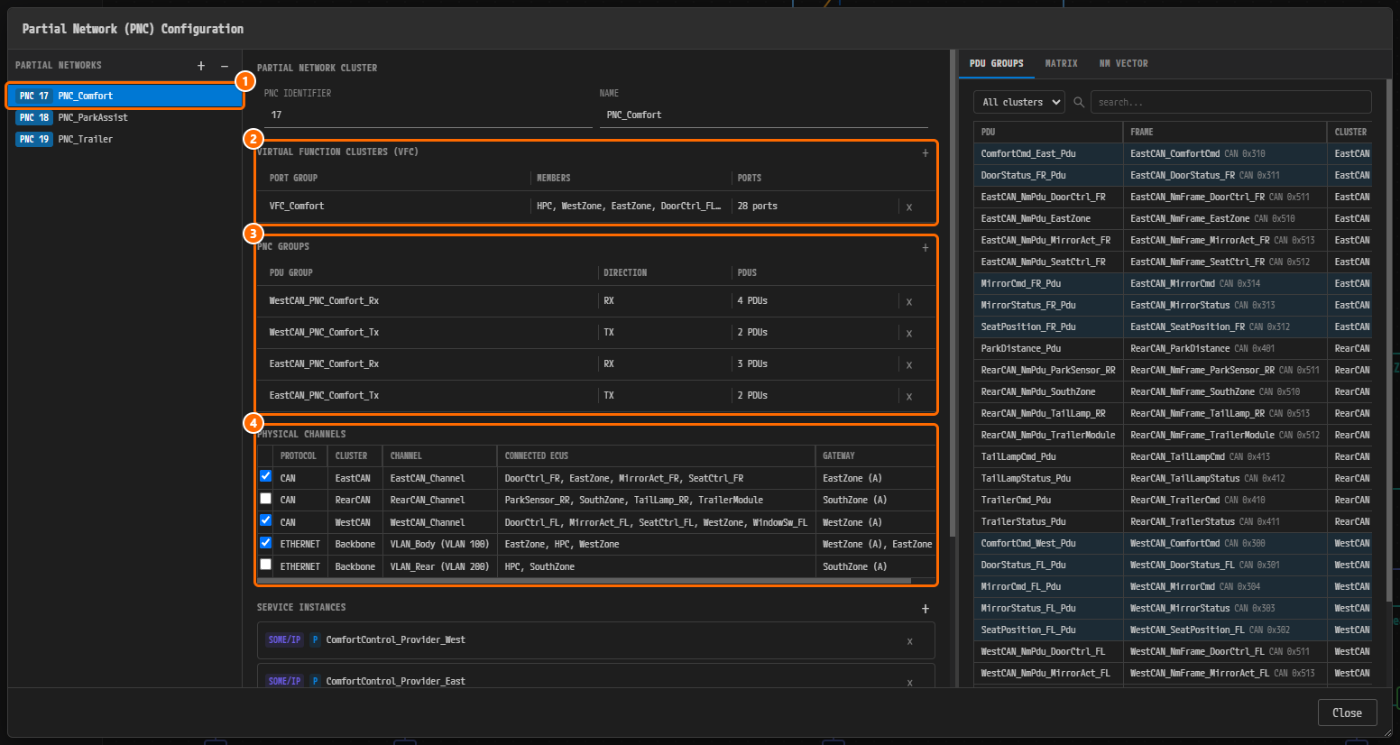
Figure 7-16. PNC 17 PNC_Comfort in the finished example (upper part). ① The list item PNC 17 PNC_Comfort. ② The VFC VFC_Comfort (28 ports). ③ Four PNC GROUPS: WestCAN_PNC_Comfort_Rx (RX, 4 PDUs), WestCAN_PNC_Comfort_Tx (TX, 2 PDUs), EastCAN_PNC_Comfort_Rx (RX, 3 PDUs) and EastCAN_PNC_Comfort_Tx (TX, 2 PDUs). ④ EastCAN_Channel, WestCAN_Channel and VLAN_Body (VLAN 100) checked in PHYSICAL CHANNELS. In the PDU GROUPS table on the right, the PDUs that belong to this PNC are highlighted.
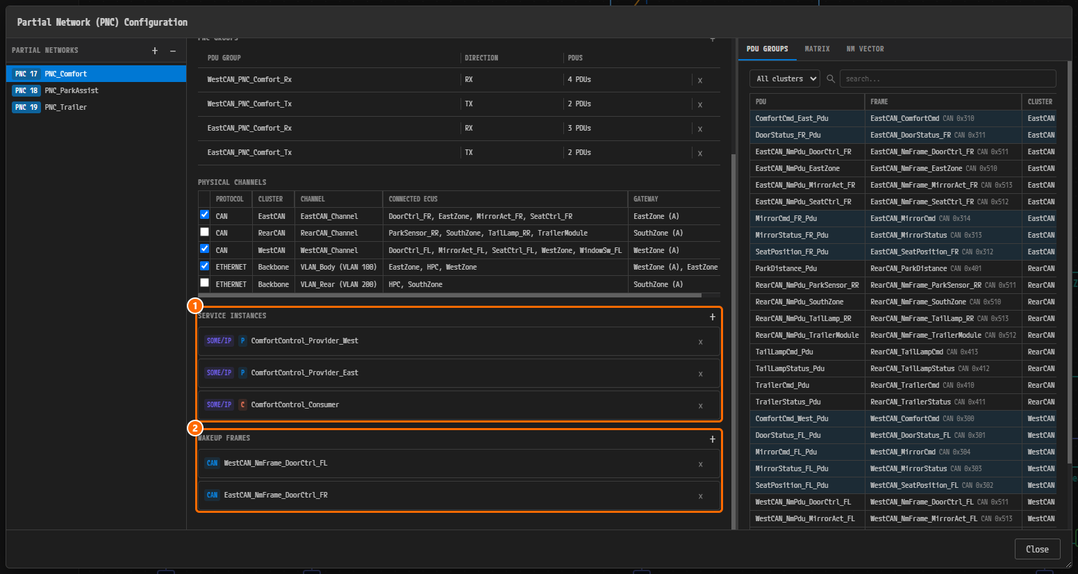
Figure 7-17. The same screen scrolled down. ① SERVICE INSTANCES: ComfortControl_Provider_West (P), ComfortControl_Provider_East (P), ComfortControl_Consumer (C). ② WAKEUP FRAMES: WestCAN_NmFrame_DoorCtrl_FL, EastCAN_NmFrame_DoorCtrl_FR.
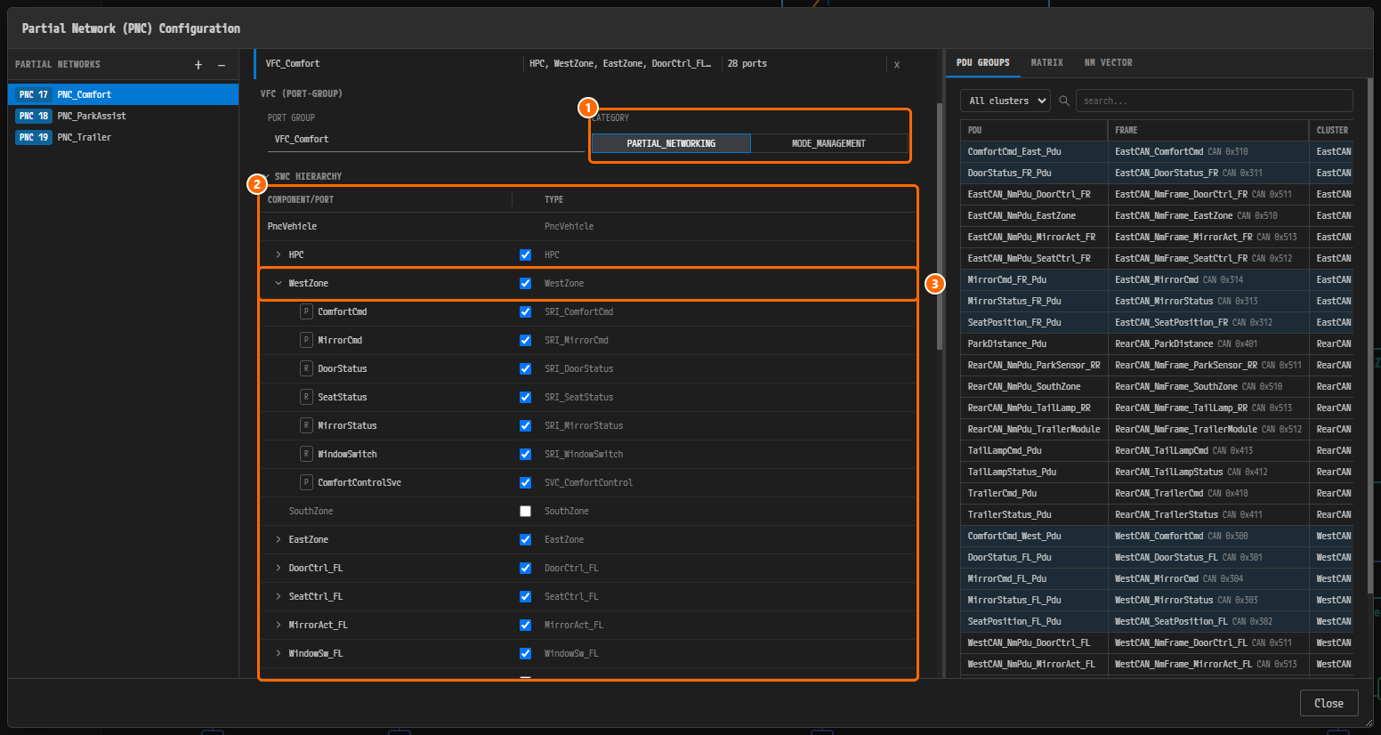
Figure 7-18. The VFC_Comfort row expanded. ① CATEGORY PARTIAL_NETWORKING. ② SWC HIERARCHY. HPC, WestZone, EastZone, DoorCtrl_FL and the others are checked, while SouthZone is not. ③ The expanded WestZone, with all seven ports checked: P ComfortCmd (SRI_ComfortCmd), P MirrorCmd, R DoorStatus, R SeatStatus, R MirrorStatus, R WindowSwitch and P ComfortControlSvc (SVC_ComfortControl). Click the > marker in front of a row to expand it down to the port level.
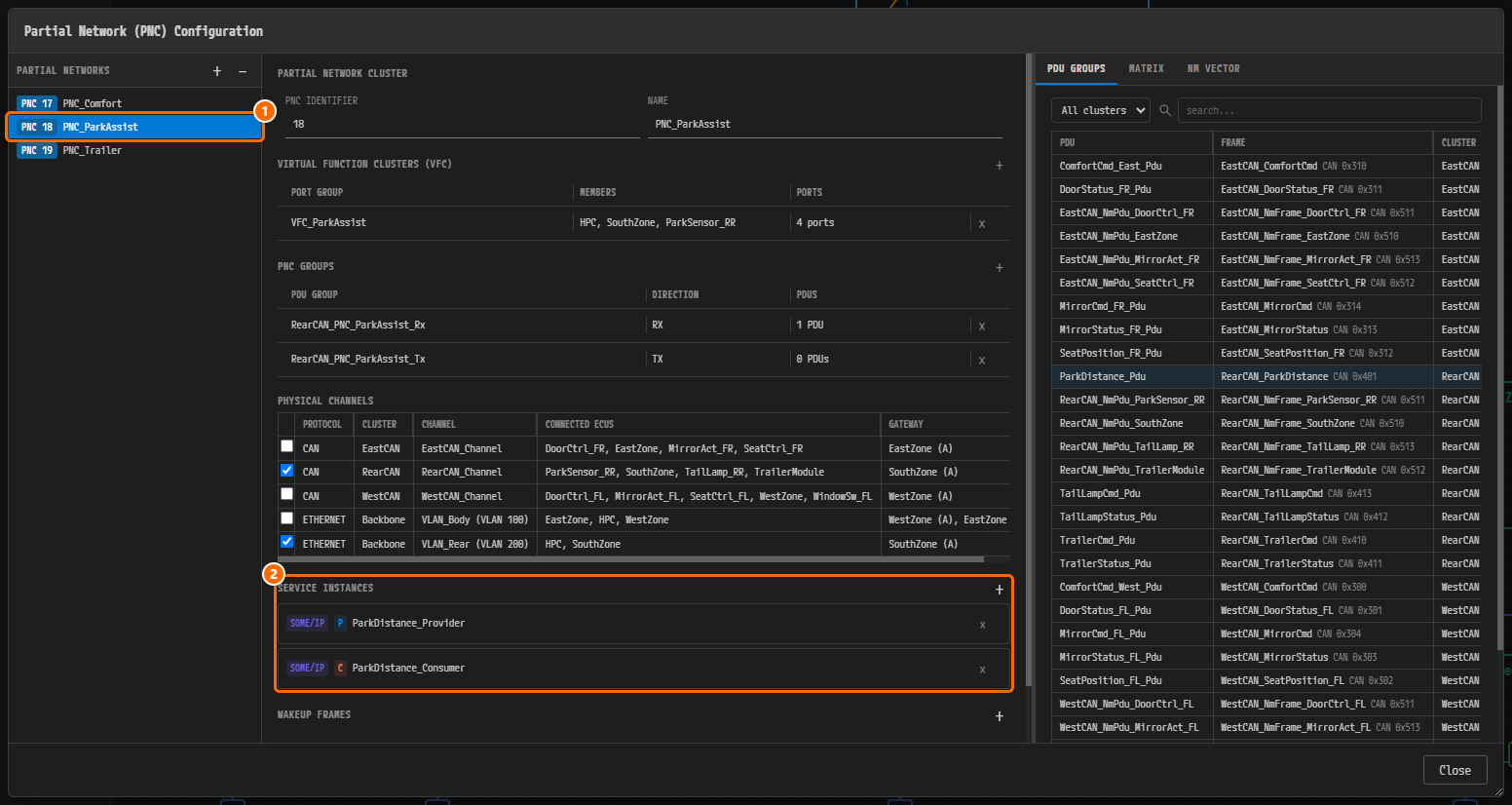
Figure 7-19. PNC 18 PNC_ParkAssist in the finished example. ① The list item PNC 18 PNC_ParkAssist. ② SERVICE INSTANCES: ParkDistance_Provider (P), ParkDistance_Consumer (C). This matches the result you entered in this chapter (Figure 7-13).
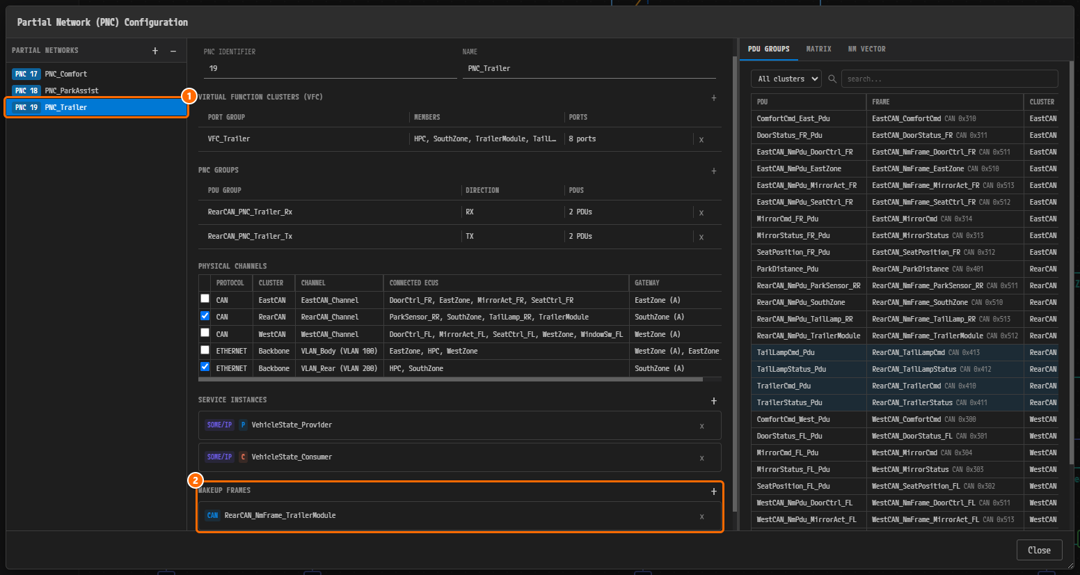
Figure 7-20. PNC 19 PNC_Trailer in the finished example (scrolled down). ① The list item PNC 19 PNC_Trailer. The center detail shows the VFC VFC_Trailer (8 ports), RearCAN_PNC_Trailer_Rx (RX, 2 PDUs) and RearCAN_PNC_Trailer_Tx (TX, 2 PDUs), the channels RearCAN_Channel and VLAN_Rear (VLAN 200), and the service instances VehicleState_Provider (P) and VehicleState_Consumer (C). ② WAKEUP FRAMES: RearCAN_NmFrame_TrailerModule.
Why Is It Designed This Way?
- One screen completes one PNC. PNC mapping in AUTOSAR references VFCs, I-PDU groups, physical channels, service instances and wakeup frames. The dialog gathers these references per PNC, so you see immediately what is missing.
- A person decides the physical channels. Which channels a PNC spans is not derived automatically from the groups or the PDUs. Each check becomes one physical channel reference in the SYSTEM model.
PNC_ParkAssisthas no wakeup frame. This PNC is requested by a FunctionGroup state on the HPC (reverse gear), not by a bus frame (see AP Machine — NM Handles and FunctionGroup).PNC_Trailerwakes up on the NM frame of the trailer module.RearCAN_NmFrame_TrailerModule(0x512) lies inside the wakeup filter block0x500..0x5FF.
Check Your Work
- The VFC table of PNC 18 PNC_ParkAssist contains
VFC_ParkAssist(HPC, SouthZone, ParkSensor_RR,4 ports). - PNC GROUPS contains
RearCAN_PNC_ParkAssist_Rx(RX,1 PDU) andRearCAN_PNC_ParkAssist_Tx(TX,0 PDUs). - In PHYSICAL CHANNELS, only
RearCAN_ChannelandVLAN_Rear (VLAN 200)are checked. - SERVICE INSTANCES contains
ParkDistance_Provider(P) andParkDistance_Consumer(C). - The WAKEUP FRAMES of PNC 19 PNC_Trailer contains
RearCAN_NmFrame_TrailerModule. - Expanding the
VFC_ParkAssistrow shows only the three rowsHPC,SouthZoneandParkSensor_RRchecked in SWC HIERARCHY. -
PNC_ComfortandPNC_Traileralso have the VFC, physical channels, service instances and wakeup frames from the table in Values for the Remaining PNCs. - There is no ● marker before the dialog title.
Next Steps
In Reviewing PDU GROUPS, MATRIX and NM VECTOR, you cross-check the PNC design with the three tabs of the viewer on the right.