AP Machine: NM Network Handles and Function Groups
What You Will Do
The HPC is an AP (Adaptive Platform) machine. It is not a PNC (Partial Network Cluster) gateway. Instead, it is a participant that requests and releases PNCs through NM (Network Management) network handles. In this chapter you open the Machine Configuration dialog of the HPC, first create the FunctionGroup that pairs with each PNC, then create the NM network handles and connect the two.
You build ParkAssistFG and NH_ParkAssist from start to finish as the worked example. For the rest, read the value table in each section and repeat the same procedure.
When you finish this chapter, the HPC machine has four FunctionGroups (MachineFG, ParkAssistFG, TrailerFG, ComfortFG) and three NM network handles (NH_Comfort, NH_ParkAssist, NH_Trailer). Each handle holds one PNC and two FunctionGroup state mappings, and the State Management module holds a MAX ACTION LIST DURATION value.
Before You Begin
- You must have finished Reviewing PDU GROUPS, MATRIX and NM VECTOR. This chapter continues from that state.
- You create three things in this chapter.
- Three FunctionGroups:
ParkAssistFG,TrailerFG,ComfortFG - The MAX ACTION LIST DURATION value
1s in the State Management module - Three NM network handles:
NH_ParkAssist,NH_Comfort,NH_Trailer. Each handle gets one PNC and two FunctionGroup state mappings.
- Three FunctionGroups:
- PAIO adds
MachineFGautomatically when you open the Machine Configuration dialog. You neither create it nor delete it. - For the full feature set of the Machine Configuration dialog, see section 8.10 of the VFB editor.
The values for ParkAssistFG and NH_ParkAssist, the worked example, are as follows.
| Item | Value |
|---|---|
| FunctionGroup NAME | ParkAssistFG |
| FunctionGroup DESCRIPTION | Park-assist function group driven by PNC_ParkAssist |
| FunctionGroup GROUP NAME / INITIAL MODE | ParkAssistState / Off |
| FunctionGroup MODE DECLARATION | Off, Active |
| Handle NAME | NH_ParkAssist |
| Handle VLANS (ETHERNET CONNECTORS) | HPC_Eth_Rear_Conn |
| Handle PARTIAL NETWORKS | PNC_ParkAssist (PNC 18) |
| Mapping 1 | ParkAssistFG:Active → FUNCTION-GROUP-STATE-TO-NM-HANDLE |
| Mapping 2 | ParkAssistFG:Off → NM-HANDLE-INACTIVE-TO-FUNCTION-GROUP-STATE |
Opening the Machine Configuration Dialog
-
In the EDITOR view on the left, click VFB under DESIGN. The VFB editor opens in the tab PNC:VFB and shows the root composition
PncVehicle. -
Find the HPC [HPC] composition on the canvas. If it looks small, zoom in with Ctrl+mouse wheel.
-
Click the machine icon (the light blue three-bar shape) to the right of the HPC [HPC] header. Do not click the square icon at the far right — it only shows that the node is a composition. Click the machine icon from the root view; you do not need to drill into the composition.
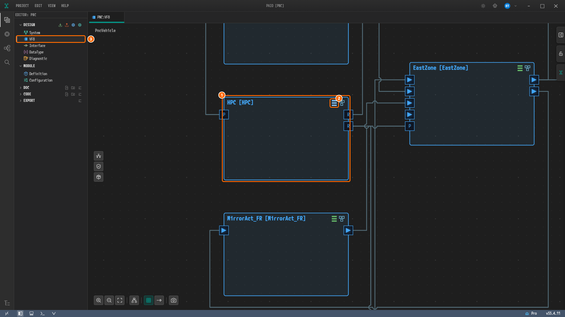
Figure 9-1. The VFB root view. ① The HPC [HPC] composition. ② The machine icon to the right of the header. Other compositions such as EastZone [EastZone] and MirrorAct_FR [MirrorAct_FR] carry a green icon in the same position. The green icon opens the ECU Configuration. ③ VFB under DESIGN in the EDITOR view.
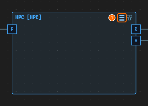
Figure 9-2. A close-up of the HPC [HPC] header. ① The machine icon to click.
-
The Machine Configuration [HPC] dialog opens on the MACHINE tab.
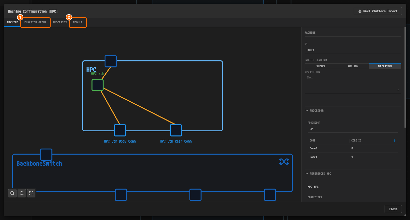
Figure 9-3. The Machine Configuration [HPC] dialog just after it opens. The tabs are MACHINE / FUNCTION GROUP / PROCESSES / MODULE. The left side shows the HPC with the connectors
HPC_Eth_Body_ConnandHPC_Eth_Rear_Conn, plusBackboneSwitch. On the right, MACHINE shows OSPOSIX, TRUSTED PLATFORM NO SUPPORT and PROCESSORCPU(Core0,Core1). The PARA Platform Import button sits at the top right and the Close button at the bottom right. ① The FUNCTION GROUP tab you click in the next step. ② The MODULE tab.
Note. The PARA Platform Import button is used in PARA Platform Import and PNC Request Ports. You do not click it in this chapter.
Reviewing the FunctionGroup Screen
An NM handle references the states of a FunctionGroup, so you must create the FunctionGroups before the handles. In this section you only look at the screen layout; you change no values.
-
Click the FUNCTION GROUP tab. Right after you open the tab nothing is selected, so the middle and right areas both read "Select a Function Group".
-
Look at the FUNCTION GROUPS list on the left. For now it holds only
MachineFG. Three buttons sit to the right of the list title.Button Tooltip What it does + Add Function Group Adds one FunctionGroup. − Remove Function Group Deletes the selected FunctionGroup. MachineFGcannot be deleted.⚡ Auto-Generate: sync StateClientInterface and SM SWC R-Ports with Function Groups Re-aligns the StateClient…interfaces and the R-Ports of the SM SWC with the current FunctionGroup list. You do not click it in this chapter. -
Click
MachineFGin the list. The middle CONFIGURATION area shows NAME, DESCRIPTION, the FUNCTION GROUP area (GROUP NAME, INITIAL MODE) and the MODE DECLARATION table, and the right STATE MACHINE area shows the state diagram. Creating a FunctionGroup means filling in these same three areas.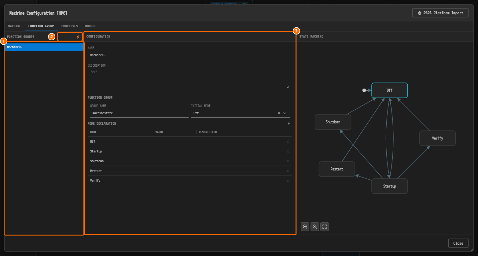
Figure 9-4. The FUNCTION GROUP tab at the start of this chapter. ① The FUNCTION GROUPS list. It holds only
MachineFG, which is selected. ② The three buttons +, − and ⚡ to the right of the list title. ③ The CONFIGURATION ofMachineFG. NAME isMachineFG, DESCRIPTION is empty, GROUP NAME isMachineState, INITIAL MODE isOff, and the MODE DECLARATION table has five rows:Off,Startup,Shutdown,Restart,Verify. On the right, STATE MACHINE draws those five states and their transitions.
Note.
MachineFGis the FunctionGroup that every AP machine always has. The NAME field is read-only, and the VALUE cells of all five MODE DECLARATION rows are empty. Leave these values as they are.
Creating a FunctionGroup
You build ParkAssistFG end to end as the worked example.
-
Click the + button (tooltip "Add Function Group") to the right of the FUNCTION GROUPS list title. A
FunctionGroup_2entry is added to the list and selected. A dirty marker (●) appears in front of the dialog title to mark unsaved changes.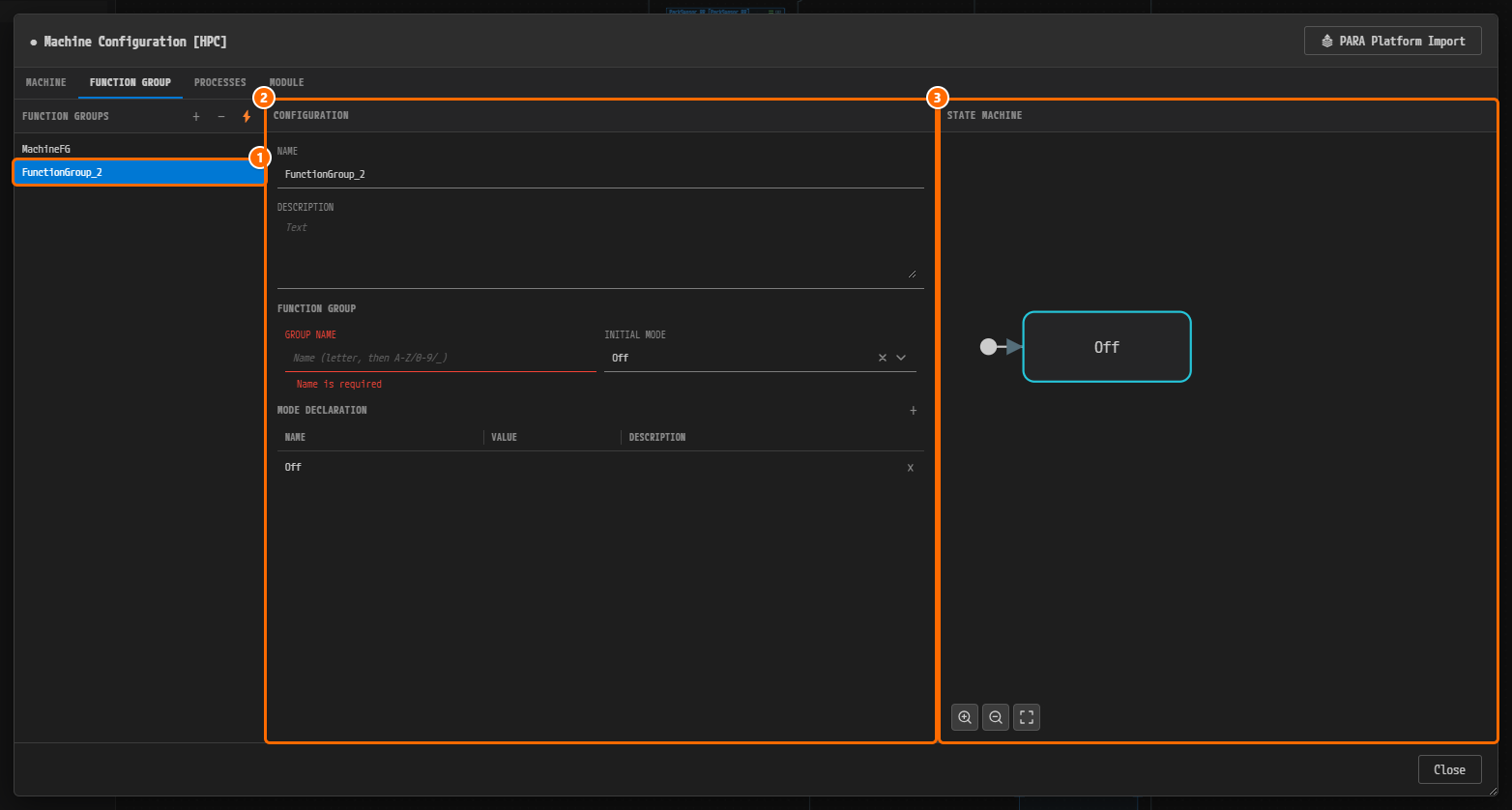
Figure 9-5. Right after clicking the + button. ①
FunctionGroup_2, added to the list and selected. ② The CONFIGURATION. NAME isFunctionGroup_2, GROUP NAME is empty and "Name is required" appears below it in red. INITIAL MODE isOff, and the MODE DECLARATION table holds the single rowOff. ③ The STATE MACHINE. It shows oneOffbox with an incoming arrow from the dot on the left. A dirty marker (●) sits in front of the dialog title. -
Type
ParkAssistFGin the NAME field of the middle CONFIGURATION area and pressTabto leave the field. The name is applied when you leave the field. The label in the left list still readsFunctionGroup_2. It refreshes when you click that entry again or add the next FunctionGroup. -
Type
Park-assist function group driven by PNC_ParkAssistin the DESCRIPTION field. -
Type
ParkAssistStatein the GROUP NAME field of the FUNCTION GROUP area and pressTab. This value becomes the name of the mode declaration group. The "Name is required" error disappears once you enter it. -
The MODE DECLARATION table already holds one row whose NAME is
Off. Click the + button (tooltip "Add Mode Declaration") to the right of the table title to add a second row. The new row has NAMEMode_0and VALUE0. Click the NAME cell, change it toActive, and click outside the table to commit. -
Check that INITIAL MODE is
Off. If it holds another value, selectOfffrom the dropdown.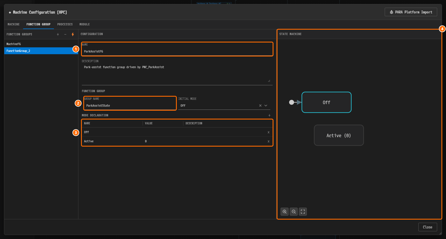
Figure 9-6. The screen with the values entered, just before you create the transitions. ① NAME
ParkAssistFG. ② GROUP NAMEParkAssistState. ③ The two MODE DECLARATION rowsOffandActive. The VALUE of theActiverow is0. ④ The STATE MACHINE. It holds the two boxesOffandActive (0)with no transition between them yet. The label in the left list still readsFunctionGroup_2. -
Right-click the
Offbox in the STATE MACHINE on the right. The menu shows Set Initial / Transition to / Delete. Hover over Transition to and the submenu lists the remaining states; click Active there. Then click Transition to › Off on theActivebox in the same way.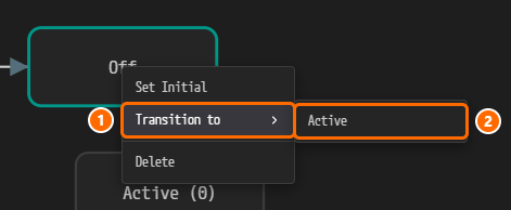
Figure 9-7. The right-click menu of the
Offbox. The items are Set Initial, Transition to and Delete. ① Transition to under the pointer. ② Active, the remaining state listed in the submenu. Clicking it creates theOff→Activetransition. -
Click the
FunctionGroup_2entry once in the FUNCTION GROUPS list on the left. The list label refreshes toParkAssistFG. Check that the result matches Figure 9-8.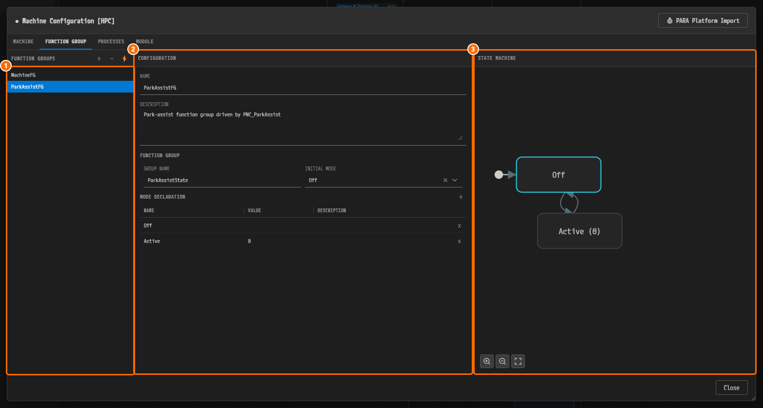
Figure 9-8.
ParkAssistFG, finished with its transitions. It is not saved yet, so the dirty marker (●) sits in front of the dialog title. ① The FUNCTION GROUPS list. The label has refreshed toParkAssistFG, so two entries appear together withMachineFG. ② The CONFIGURATION. The NAME, DESCRIPTION and GROUP NAME values and the two MODE DECLARATION rows are filled in. ③ The STATE MACHINE. Two transitions are drawn as short curves betweenOffandActive (0). -
Press Ctrl+S to save. The dirty marker (●) in front of the title disappears.
Note 1. A row created with + gets
0in its VALUE cell automatically, and the box in the STATE MACHINE shows the value too, as inActive (0). The example model does not carry this value, so the VALUE cell in Figure 9-9 is empty and the box is simply namedActive. This does not affect the result of the tutorial, so leave it as it is.
Note 2. Boxes created with + are placed diagonally to each other, so the two transitions overlap (Figure 9-8). In the example model the two boxes sit side by side horizontally, so the two transitions are drawn separately (Figure 9-9). You can drag the boxes, and their position affects only the diagram.
Note 3. Adding a FunctionGroup also creates a
StateClient_<FunctionGroup name>interface on the ADAPTIVE tab of the Interface editor. When you finish this chapter you have three of them:StateClient_ParkAssistFG,StateClient_TrailerFGandStateClient_ComfortFG.StateClient_HPC_MachineFGarrives in PARA Platform Import and PNC Request Ports. When you delete a FunctionGroup, the confirmation dialog tells you that this interface is deleted with it. This tutorial does not touch these interfaces separately.
Creating the Remaining FunctionGroups
Repeat the same procedure for TrailerFG and ComfortFG. The values of the four finished FunctionGroups are as follows.
| NAME | DESCRIPTION | GROUP NAME | INITIAL MODE | MODE DECLARATION | Transitions |
|---|---|---|---|---|---|
MachineFG | (empty) | MachineState | Off | Off, Startup, Shutdown, Restart, Verify | Present automatically |
ParkAssistFG | Park-assist function group driven by PNC_ParkAssist | ParkAssistState | Off | Off, Active | Off → Active, Active → Off |
TrailerFG | Trailer function group driven by PNC_Trailer | TrailerState | Off | Off, Active | Off → Active, Active → Off |
ComfortFG | Comfort function group driven by PNC_Comfort | ComfortState | Off | Off, Active | Off → Active, Active → Off |
-
Repeat steps 1 through 9 of Creating a FunctionGroup to create
TrailerFG. Use the values from the table above. The + button names the next entriesFunctionGroup_3and thenFunctionGroup_4. -
Create
ComfortFGthe same way. -
Click
ParkAssistFGin the list and check that the result matches Figure 9-9.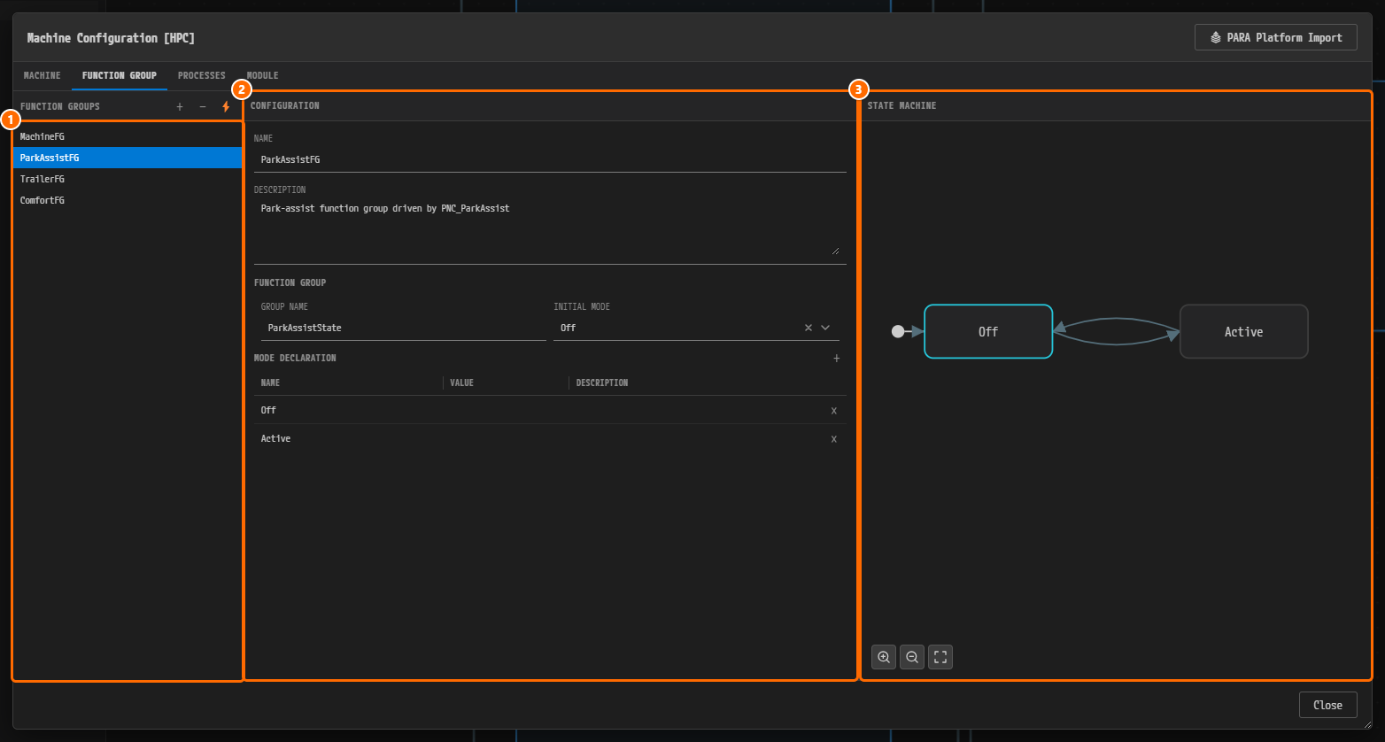
Figure 9-9. The finished FUNCTION GROUP tab. ① The FUNCTION GROUPS list. It holds the four entries
MachineFG,ParkAssistFG,TrailerFGandComfortFG, withParkAssistFGselected. ② The CONFIGURATION. NAME isParkAssistFG, DESCRIPTION isPark-assist function group driven by PNC_ParkAssist, GROUP NAME isParkAssistState, INITIAL MODE isOff, and the MODE DECLARATION table has the two rowsOffandActive. ③ The STATE MACHINE. The two transitions betweenOffandActiveappear in the diagram. The arrow that entersOfffrom the dot at the far left marks the INITIAL MODE.
Caution. The FunctionGroups and states you use for the mappings in the later sections must actually exist on this tab. If a name or a state name differs from the table, it does not appear in the mapping checklist. The FunctionGroups you created here show up as the 11 candidates in
<FunctionGroup>:<state>form in Adding FunctionGroup State Mappings later on.
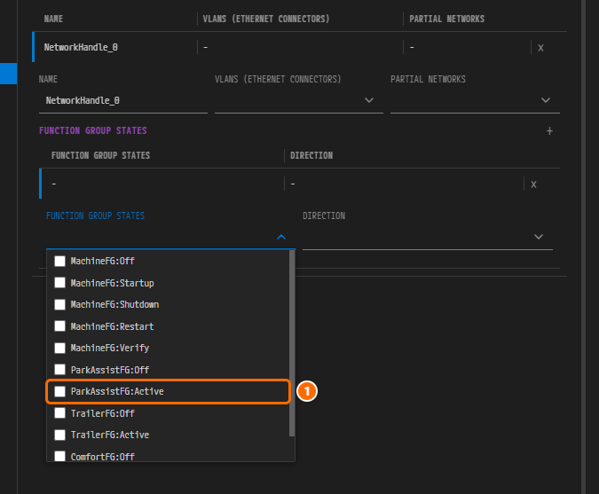
Figure 9-10. The FUNCTION GROUP STATES checklist you see in a later section. After the five entries of MachineFG come the Off and Active states of the ParkAssistFG, TrailerFG and ComfortFG you just created. ① ParkAssistFG:Active. The handle is still named NetworkHandle_0 because it was added only moments ago to show this list.
Entering MAX ACTION LIST DURATION in State Management
The State Management module must carry a maximum execution time for its action lists. You enter that value here.
-
Click the MODULE tab, then click State Management in the MODULES list on the left.
Note. The MODULES list always shows the same 11 modules. There is no button to add a module to the list or remove one from it. The green dot in front of each module shows that the module is enabled (tooltip "Enabled. Right-click to disable."). Leave every module enabled in this tutorial.
-
Among the middle sub-tabs NOTIFICATIONS / REQUESTS / ACTION ITEMS, click ACTION ITEMS.
-
Type
1in the MAX ACTION LIST DURATION field at the top and click elsewhere to commit. The value is applied when you leave the field. The unit dropdown to the right of the field readss(seconds). Leave it as it is.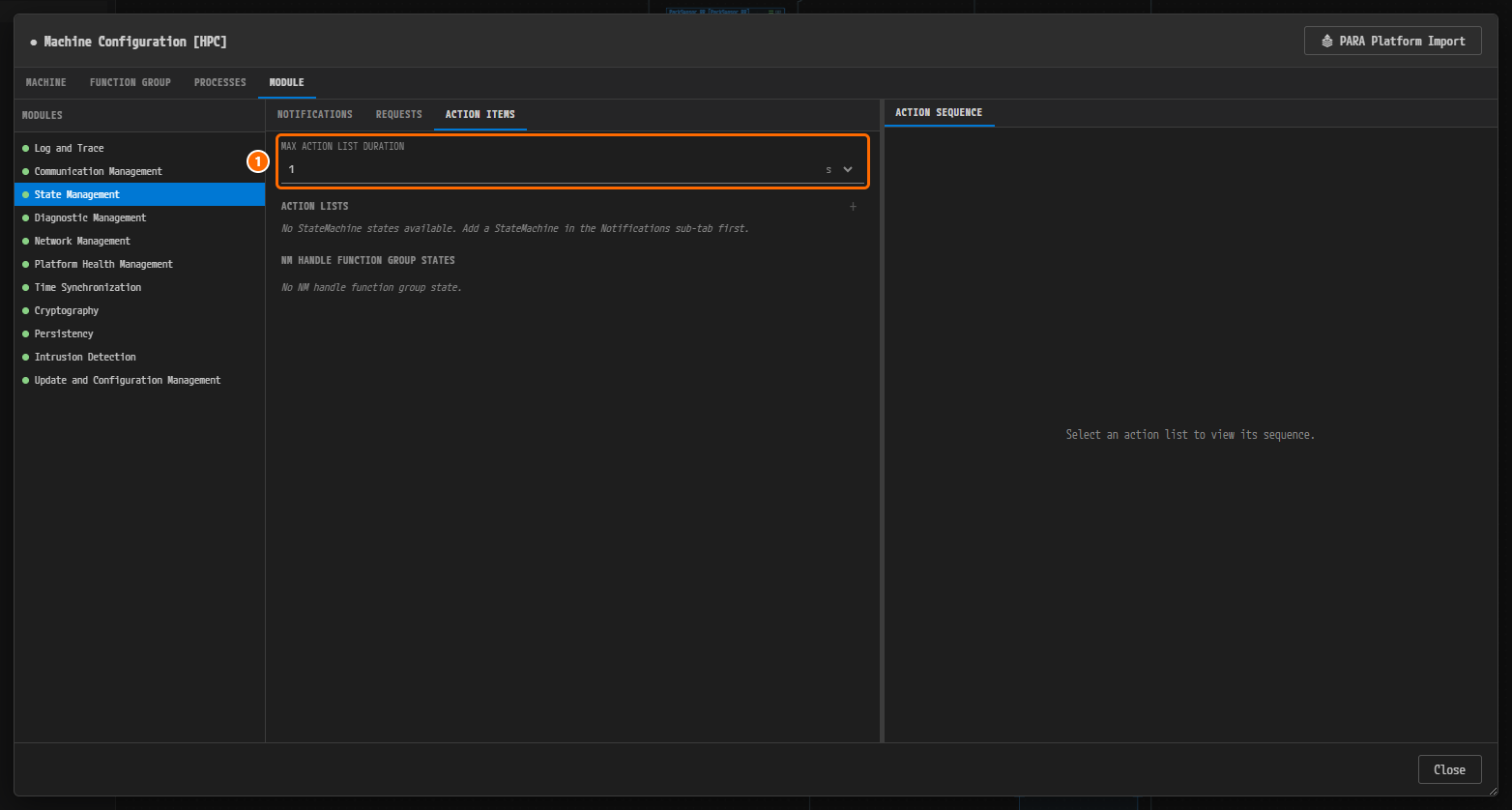
Figure 9-11. State Management › ACTION ITEMS. ① The MAX ACTION LIST DURATION value
1you entered, with the unitson its right. Below it, NM HANDLE FUNCTION GROUP STATES reads "No NM handle function group state." because no handle exists yet. This table fills in once you create the handles in a later section. The MODULES list on the left shows the 11 modules. -
Save with Ctrl+S.
Note. The message "No StateMachine states available. Add a StateMachine in the Notifications sub-tab first." under ACTION LISTS appears because this example has no SM notification. Leave it as it is for this tutorial.
Caution. If you leave the MAX ACTION LIST DURATION field empty, PAIO validation reports the error
constr_10641. The State Management module must carry this value.
Adding an NM Network Handle
-
Click Network Management in the MODULES list on the left. The NETWORK HANDLES section appears in the middle. No handle exists yet, so it reads "No network handles. Click + to add one and assign its VLAN (Ethernet connector) group."
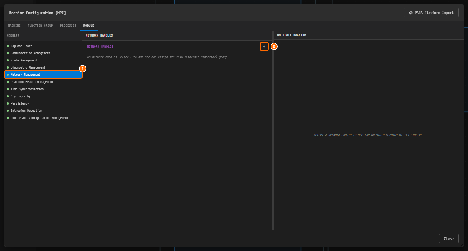
Figure 9-12. Network Management on the MODULE tab. ① Network Management in the MODULES list. ② The + button (tooltip "Add Network Handle") to the right of the NETWORK HANDLES title. On the right, NM STATE MACHINE reads "Select a network handle to see the NM state machine of its cluster."
-
Click the + button to the right of the NETWORK HANDLES title. A
NetworkHandle_0row is added and immediately expanded. A dirty marker (●) appears in front of the dialog title to mark unsaved changes.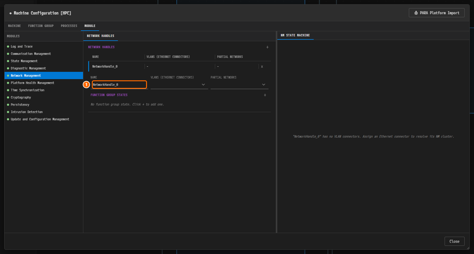
Figure 9-13. Right after clicking +. The summary row at the top shows NAME / VLANS (ETHERNET CONNECTORS) / PARTIAL NETWORKS as
NetworkHandle_0/-/-. The expanded detail below holds the same three fields plus the FUNCTION GROUP STATES subheading. ① The NAME field. On the right, NM STATE MACHINE reports that the handle has no VLAN connector. -
Type
NH_ParkAssistin the NAME field of the expanded detail and pressTab. -
The name is committed and the summary row now reads
NH_ParkAssist. The row stays expanded. -
Click the VLANS (ETHERNET CONNECTORS) field. Check HPC_Eth_Rear_Conn in the checklist and press
Escto close the list.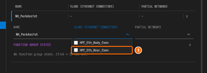
Figure 9-14. The VLANS (ETHERNET CONNECTORS) checklist. It lists the two Ethernet connectors of the HPC,
HPC_Eth_Body_ConnandHPC_Eth_Rear_Conn. ① HPC_Eth_Rear_Conn, the one to check. -
Click the PARTIAL NETWORKS field. Check PNC_ParkAssist (PNC 18) in the checklist and press
Escto close the list.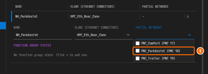
Figure 9-15. The PARTIAL NETWORKS checklist. The VLANS (ETHERNET CONNECTORS) value in the summary row has changed to
HPC_Eth_Rear_Conn. The list shows the three PNCs created in PNC Definitions and Connector PNC Properties asPNC_Comfort (PNC 17),PNC_ParkAssist (PNC 18)andPNC_Trailer (PNC 19). ① PNC_ParkAssist (PNC 18), the one to check.
Adding FunctionGroup State Mappings
You add two mappings to NH_ParkAssist. The first requests PNC_ParkAssist when ParkAssistFG becomes Active. The second drops ParkAssistFG to Off when PNC_ParkAssist becomes inactive.
-
Click the + button (tooltip "Add Function Group State") to the right of the FUNCTION GROUP STATES subheading inside the expanded handle. A mapping row is added and immediately expanded, showing the two fields FUNCTION GROUP STATES and DIRECTION.
-
Click the FUNCTION GROUP STATES field. Check ParkAssistFG:Active in the checklist and press
Escto close the list.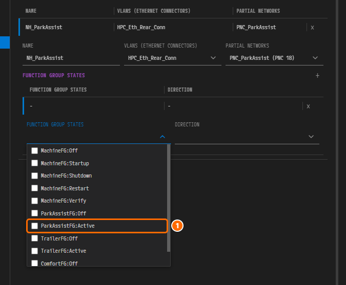
Figure 9-16. The FUNCTION GROUP STATES checklist right after you add a mapping row. There are 11 candidates in
<FunctionGroup>:<state>form. They come from the FunctionGroups created in the previous sections: five fromMachineFGand two each fromParkAssistFG,TrailerFGandComfortFG. Scroll down the list to reachComfortFG:Active. ① ParkAssistFG:Active, the one to check. -
Click the DIRECTION field and select FUNCTION-GROUP-STATE-TO-NM-HANDLE.
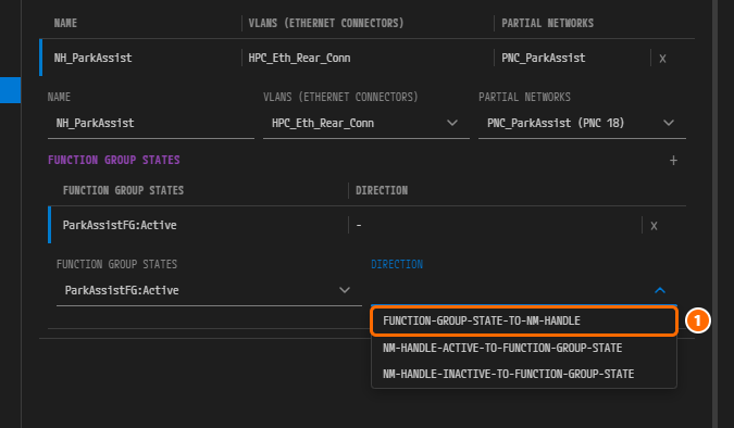
Figure 9-17. The DIRECTION dropdown. The three choices are FUNCTION-GROUP-STATE-TO-NM-HANDLE, NM-HANDLE-ACTIVE-TO-FUNCTION-GROUP-STATE and NM-HANDLE-INACTIVE-TO-FUNCTION-GROUP-STATE. The mapping summary row already carries
ParkAssistFG:Active. ① FUNCTION-GROUP-STATE-TO-NM-HANDLE, the one to select. -
Click the + button to the right of the FUNCTION GROUP STATES subheading again. A second mapping row is added.
-
In the new lower mapping row, use the same procedure as in steps 1 through 3 to select ParkAssistFG:Off for FUNCTION GROUP STATES and NM-HANDLE-INACTIVE-TO-FUNCTION-GROUP-STATE for DIRECTION.
-
Press Ctrl+S inside the dialog to save. The dirty marker (●) in front of the title disappears.
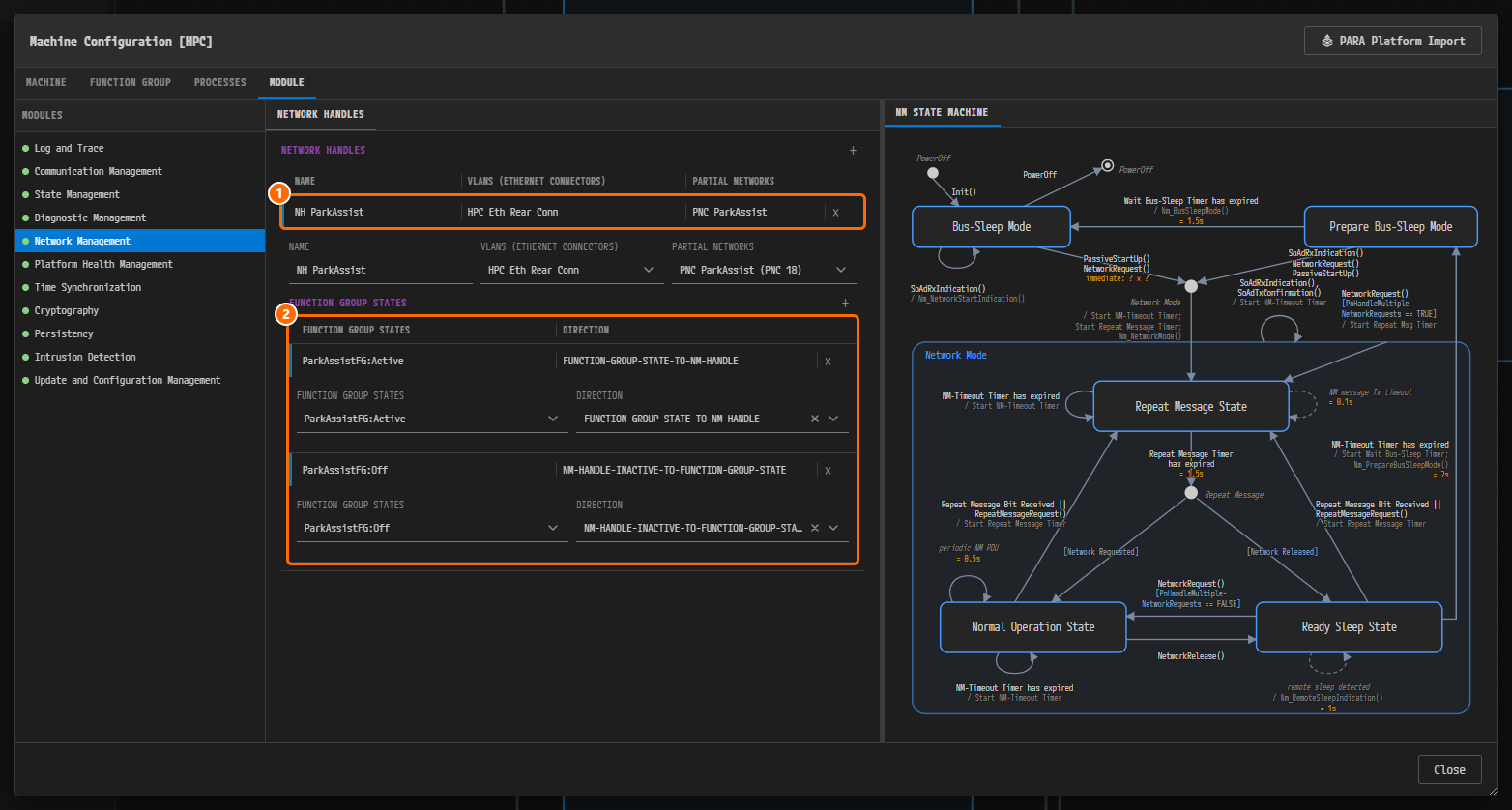
Figure 9-18.
NH_ParkAssistafter saving. ① The handle summary row:NH_ParkAssist/HPC_Eth_Rear_Conn/PNC_ParkAssist. ② The two mapping rows of the FUNCTION GROUP STATES table:ParkAssistFG:Active/FUNCTION-GROUP-STATE-TO-NM-HANDLEandParkAssistFG:Off/NM-HANDLE-INACTIVE-TO-FUNCTION-GROUP-STATE. On the right, NM STATE MACHINE shows the NM state machine diagram of the cluster that the VLAN of the handle belongs to. -
Click State Management in the MODULES list and look at the ACTION ITEMS tab. The NM HANDLE FUNCTION GROUP STATES table, empty in the previous section, now holds the two mapping rows you just created.
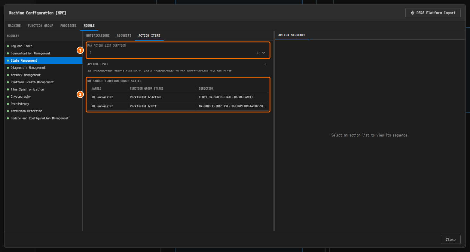
Figure 9-19. State Management › ACTION ITEMS. ① The MAX ACTION LIST DURATION value
1entered in the previous section, with the units. ② The NM HANDLE FUNCTION GROUP STATES table. The two mappings ofNH_ParkAssistappear in the HANDLE / FUNCTION GROUP STATES / DIRECTION columns. This table is read-only; you edit the mappings on the Network Management side.
Note. The DIRECTION field of an expanded mapping is narrow, so a long value is truncated, as in
NM-HANDLE-INACTIVE-TO-FUNCTION-GROUP-STA…. The mapping summary row shows the whole value.
The saved handle is recorded in the machine file design/Module/Machine/HPC.machine.io.model as follows. The PNC you selected in the PARTIAL NETWORKS field is stored as a path (/System/PncVehicle/SystemMapping/PNC_ParkAssist). The key order in the actual file may differ from the listing below, but the content is the same.
{
  "name": "NH_ParkAssist",
  "vlan-refs": ["HPC_Eth_Rear_Conn"],
  "partial-network-refs": ["/System/PncVehicle/SystemMapping/PNC_ParkAssist"],
  "function-group-state-mappings": [
    { "mapping-direction": "FUNCTION-GROUP-STATE-TO-NM-HANDLE",
      "function-group-states": [{ "context-function-group-ref": "ParkAssistFG", "target-state-ref": "Active" }] },
    { "mapping-direction": "NM-HANDLE-INACTIVE-TO-FUNCTION-GROUP-STATE",
      "function-group-states": [{ "context-function-group-ref": "ParkAssistFG", "target-state-ref": "Off" }] }
  ]
}
Adding the Remaining Handles
Add NH_Comfort and NH_Trailer the same way. The values of the three handles are as follows.
| NAME | VLANS (ETHERNET CONNECTORS) | PARTIAL NETWORKS | FUNCTION GROUP STATES | DIRECTION |
|---|---|---|---|---|
NH_Comfort | HPC_Eth_Body_Conn | PNC_Comfort (PNC 17) | ComfortFG:Active | NM-HANDLE-ACTIVE-TO-FUNCTION-GROUP-STATE |
ComfortFG:Off | NM-HANDLE-INACTIVE-TO-FUNCTION-GROUP-STATE | |||
NH_ParkAssist | HPC_Eth_Rear_Conn | PNC_ParkAssist (PNC 18) | ParkAssistFG:Active | FUNCTION-GROUP-STATE-TO-NM-HANDLE |
ParkAssistFG:Off | NM-HANDLE-INACTIVE-TO-FUNCTION-GROUP-STATE | |||
NH_Trailer | HPC_Eth_Rear_Conn | PNC_Trailer (PNC 19) | TrailerFG:Active | NM-HANDLE-ACTIVE-TO-FUNCTION-GROUP-STATE |
TrailerFG:Off | NM-HANDLE-INACTIVE-TO-FUNCTION-GROUP-STATE |
The DIRECTION values mean the following.
| DIRECTION | Meaning | In this example |
|---|---|---|
FUNCTION-GROUP-STATE-TO-NM-HANDLE | When the FunctionGroup enters this state, the handle requests its PNC. | When ParkAssistFG becomes Active (reverse gear), it requests PNC_ParkAssist. |
NM-HANDLE-ACTIVE-TO-FUNCTION-GROUP-STATE | When the PNC of the handle becomes active, the FunctionGroup moves to this state. | When PNC_Comfort and PNC_Trailer come up, ComfortFG and TrailerFG move to Active. |
NM-HANDLE-INACTIVE-TO-FUNCTION-GROUP-STATE | When the PNC of the handle becomes inactive, the FunctionGroup moves to this state. | When the PNCs go to sleep, all three FunctionGroups drop to Off. |
-
Click Network Management again in the MODULES list.
-
Repeat steps 2 through 6 of Adding an NM Network Handle and steps 1 through 5 of Adding FunctionGroup State Mappings to create
NH_Comfort. Use the values from the table above. -
Create
NH_Trailerthe same way. -
Save with Ctrl+S.
-
Check that
NH_Comfortmatches Figure 9-20. A click on a summary row expands or collapses that row, so click the summary rowNH_Comfortonly if it is collapsed. Your screen can differ from the figure: rows you added earlier may still be expanded, and the row order follows the order in which you created the handles, so if you followed this procedure,NH_ParkAssistcomes first. Only the values need to match the table.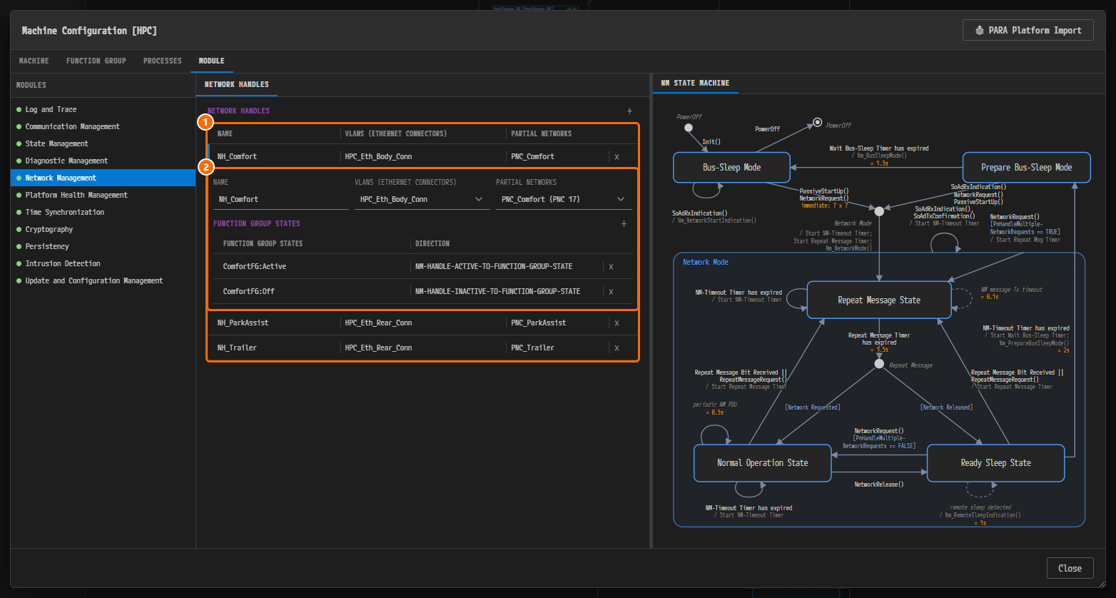
Figure 9-20. The finished NETWORK HANDLES. ① The three handle rows
NH_Comfort,NH_ParkAssistandNH_Trailer. ② The expanded detail ofNH_Comfort. PARTIAL NETWORKS isPNC_Comfort (PNC 17), and the mappings areComfortFG:Active/NM-HANDLE-ACTIVE-TO-FUNCTION-GROUP-STATEandComfortFG:Off/NM-HANDLE-INACTIVE-TO-FUNCTION-GROUP-STATE. -
Open State Management › ACTION ITEMS again and the NM HANDLE FUNCTION GROUP STATES table shows the six mapping rows of the three handles.
-
Click the Close button to close the dialog. If you have saved, it closes without a save confirmation.
Caution. If a handle that references a PNC has no
NM-HANDLE-INACTIVE-TO-FUNCTION-GROUP-STATEmapping, PAIO validation reports the error "PNC release stops nothing" for that handle. It means that nothing stops when the PNC is released. Always give a handle with a PARTIAL NETWORKS value at least one mapping in the INACTIVE direction.
Why Is It Designed This Way?
- The PNC gateway type (PNC GATEWAY TYPE) is a property of CP (Classic Platform) ECU connectors only. The HPC, an AP machine, cannot be a PNC gateway. Instead, the NM network handles of ara::nm reference the PNCs, which makes the HPC both a requester of and a participant in those PNCs.
- A FunctionGroup is the unit by which an AP machine starts and stops applications. Giving each PNC its own FunctionGroup groups the applications that run while that PNC is alive under a single state.
- Connecting handles and FunctionGroup states in both directions lets you declare behavior such as "reverse gear =
ParkAssistFGActive→ requestPNC_ParkAssist" and "PNC_Comfortactive →ComfortFGActive" in the design model. PNC_ParkAssisthas no wakeup frame. This PNC is requested by a FunctionGroup state on the HPC rather than by a bus frame.
Check Your Work
- The FUNCTION GROUPS list on the FUNCTION GROUP tab holds the four entries
MachineFG,ParkAssistFG,TrailerFGandComfortFG. - The GROUP NAME and MODE DECLARATION values of
ParkAssistFG,TrailerFGandComfortFGmatch the table in Creating the Remaining FunctionGroups, and INITIAL MODE isOfffor all three. - The STATE MACHINE diagram of all three FunctionGroups has the transitions
Off→ActiveandActive→Off. - The MAX ACTION LIST DURATION value on State Management › ACTION ITEMS is
1s. - NETWORK HANDLES under Network Management holds the three rows
NH_Comfort,NH_ParkAssistandNH_Trailer. - The VLANS (ETHERNET CONNECTORS) and PARTIAL NETWORKS values of each handle match the table in Adding the Remaining Handles.
- Each handle has two mappings, one of them in the
NM-HANDLE-INACTIVE-TO-FUNCTION-GROUP-STATEdirection. - The
ParkAssistFG:Activemapping ofNH_ParkAssistis in theFUNCTION-GROUP-STATE-TO-NM-HANDLEdirection. - The NM HANDLE FUNCTION GROUP STATES table on State Management › ACTION ITEMS holds six rows.
- The dialog closed without a save confirmation when you clicked the Close button, which means everything was saved.
Next Steps
In PARA Platform Import and PNC Request Ports you import the PARA platform into the HPC and connect the application AAs so that they request PNCs through the NM network handles. The next chapter uses the four FunctionGroups and three NM network handles created here as they are, so check that every value from the tables above is in place before you move on.