PNC Design Tutorial
This tutorial designs three PNCs (Partial Network Clusters) for a zonal vehicle and follows how that design is recorded in each PAIO editor, in this order: System editor, Signal, Interface, VFB, Machine Configuration, and the SYSTEM panel. At the end you export the finished model to AUTOSAR ARXML and confirm the PNC mappings in the result.
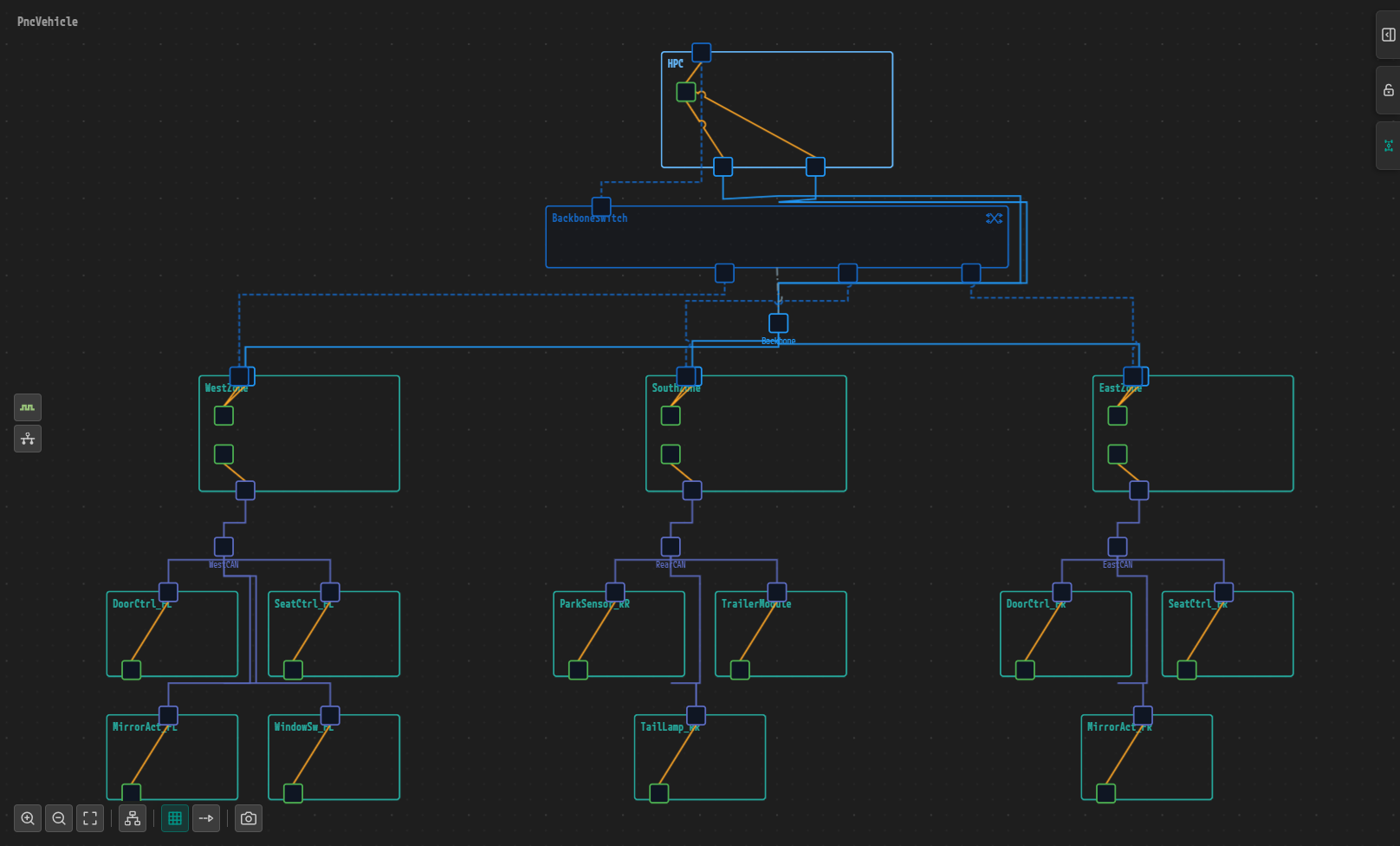
The vehicle you build in this tutorial. At the top is the HPC running on the AUTOSAR Adaptive Platform together with its built-in backbone switch, in the middle are three zone ECUs, and at the bottom are ten end ECUs attached to three CAN FD buses.
What You Build
You express a vehicle-level requirement with three PNCs: "when a door opens, wake only the Comfort network; the park assist network comes alive only in reverse gear; the trailer network runs only while a trailer is attached."
| PNC | Identifier | Wakeup trigger |
|---|---|---|
PNC_Comfort | 17 | Door unlock, door open |
PNC_ParkAssist | 18 | Reverse gear. The HPC requests it. |
PNC_Trailer | 19 | Trailer attached |
Who This Is For
This tutorial is for engineers who design AUTOSAR vehicle networks with PAIO. It assumes you know roughly what a PNC is but not which PAIO screen takes which input. You do not need a prepared project. Chapter 2 starts from a PAIO window with no project open.
What You Need
| Item | Value |
|---|---|
| PAIO version | 0.6.0 |
| AUTOSAR release | R25-11 |
| Screen | 1920×1080 or larger. The PNC dialog and the Machine Configuration dialog are wide. |
| License | An active license and a server connection. Needed only in Chapter 12 (ARXML export). |
Chapter Flow
| Chapter | What you do | Editor used |
|---|---|---|
| 1. Example and Design Goals | Derive three PNCs from the vehicle scenario and identify the five layers a PNC spans | — |
| 2. Topology Design | Create the project and place the nodes, clusters, backbone switch, and coupling ports | System editor |
| 3. PNC Definitions and Connector PNC Properties | Define the three PNCs, enter gateway, wakeup, and filter mask values on the connectors, then fill in the NM cluster and NM node values that carry the PNC bits | System editor, PNC dialog, communication cluster dialog |
| 4. Signals, PDUs, Frames, and I-PDU Groups | Create and map the CAN frames, I-Signal I-PDUs, signals, and NM-PDUs, then create the eight per-PNC Rx/Tx I-PDU Groups and bind them to the PNCs | Signal, PNC dialog |
| 5. Interfaces and SOME/IP Services | Create the service interfaces and the SOME/IP deployment, then bind the instances to the connectors | Interface, System editor |
| 6. VFB and VFC (PortGroup) | Create one composition and its atomic SWCs per node and connect them, then group the SWC ports that take part in a function into a PortGroup (= VFC) | VFB |
| 7. PNC Dialog — Per-PNC Bindings | Bind the VFCs, I-PDU Groups, physical channels, service instances, and wakeup frames for each PNC | PNC dialog |
| 8. Reviewing PDU GROUPS, MATRIX, and NM VECTOR | Cross-check the design in the three viewer tabs | PNC dialog |
| 9. AP Machine — NM Handles and FunctionGroups | Add three FunctionGroups and the State Management values to the HPC, then create three NM network handles and map them to the FunctionGroup states | VFB, Machine Configuration |
| 10. PARA Platform Import and PNC Request Ports | Import PARA, then attach the ara::nm ports and the handle mappings to the application AA | VFB, Interface, Machine Configuration |
| 11. System Editor and Validation | Check the SYSTEM panels, read the VALIDATION panel, and fix the reported items | System editor, VFB, Interface, VALIDATION panel |
| 12. ARXML Export | Export the finished design and confirm the PNC mappings in the result | EDITOR view, XML editor |
| Appendix | Design checklist, project file structure, model fragments, and common problems | — |
Each chapter builds on the result of the previous one, so follow them in order. The Before You Begin section at the start of every chapter states what the model must contain when you start that chapter. There is only one place where you go back. The NM-PDU references in the NM configuration of Chapter 3 can be filled in only after you create the NM-PDUs in Chapter 4, so you return to Chapter 3 once after finishing Chapter 4. Both chapters point this out at the relevant step.
Note. This tutorial starts from a PAIO window with no project open and builds the model from scratch. For repetitive input (42 signals, 14 compositions, 33 PortGroups, and so on), one representative item is shown as a full procedure and the rest are given as value tables. You enter the table items yourself by repeating the same operation. On some screens the number of items in the screenshot differs from the number in the project you build, and those chapters state the difference up front in Before You Begin.
Next Steps
Start with Example and Design Goals.