SOME/IP Deployment and Service Instances
What You Will Do
In this chapter you attach one SOME/IP deployment and three service instances to the interface Sensor that you created in The Service Interface.
In the SOA DEPLOYMENT panel on the right of the Interface editor, you use the + button to add a SOME/IP deployment, set the SERVICE ID to 11, and rename the event group to Eventgroup_SensorData. Then you use the + button of the deployment card to create one provider (Provider) and two consumers (Consumer), and in the SERVICE INSTANCE panel you rename them to Provider_Sensor, Actuator_Sensor and Fusion_Sensor, set the timing values in SD SERVER CONFIG / SD CLIENT CONFIG to the reference design values, and save.
When you finish this chapter, a new file design/SERVICE.io.model exists and holds the deployment Sensor, the provider Provider_Sensor and the consumers Actuator_Sensor and Fusion_Sensor. The three instances are bound to the UDP ports of the Ethernet connector in Binding Service Instances to the Connector and connected to the AA ports in Service Instance Mapping.
Before You Begin
- Start from the state at the end of The Service Interface. The
design/folder holdsINTERFACE.io.model(service interfaceSensor), and neitherSERVICE.io.modelnorSIGNAL.io.modelexists yet. The VALIDATION panel showsNo validation issues.. - If the tab
AADesign:Interfaceis still open, keep using it. If you closed it, click Interface under DESIGN in the EDITOR view to open it again.
The values you type or change in this chapter are listed below. Every field not in the tables keeps its default.
| Element | Default name → NAME to type | Other values |
|---|---|---|
| SOME/IP deployment | Sensor (unchanged) | SERVICE ID 11, MAJOR VERSION 1 / MINOR VERSION 0 (defaults) |
| Event deployment | SensorData (automatic) | EVENT ID 1, TRANSPORT UDP (all defaults) |
| Method deployment | Calculation (automatic) | METHOD ID 1, TRANSPORT UDP (all defaults) |
| Event group | EG_SensorData → Eventgroup_SensorData | EVENTGROUP ID 1, EVENTS SensorData (all defaults) |
| Provider | Provider_Sensor_1 → Provider_Sensor | INSTANCE ID 1 (default) |
| Consumer 1 | Consumer_Sensor_1 → Actuator_Sensor | REQUIRED INSTANCE ID ANY (default) |
| Consumer 2 | Consumer_Sensor_2 → Fusion_Sensor | REQUIRED INSTANCE ID ANY (default) |
The SD (Service Discovery) timing goes into SD SERVER CONFIG of the provider and SD CLIENT CONFIG of the consumers. A time field is used together with the unit selector to the right of the value (ns, us, ms, s); the "Value to enter" column below includes the unit.
| Field | Default | Value to enter | Provider | Consumer |
|---|---|---|---|---|
| INITIAL DELAY MIN | 10 ms | 10 us | enter | enter |
| INITIAL DELAY MAX | 100 ms | 100 us | enter | enter |
| REPETITION BASE DELAY | 200 ms | 200 us | enter | enter |
| REPETITION MAX | 3 | keep | default | default |
| OFFER CYCLIC DELAY | 500 ms | 1 ms | enter | no field |
| TTL | 0xFFFFFF | keep | default | default |
| REQUEST RESPONSE DELAY MIN / MAX | 0 s / 0 s | keep | default | no field |
Caution. In the PAIO build used for this chapter, editing two or more SD fields of the same card one after another keeps only the last edited field and resets the earlier ones to their defaults. For that reason, each time you enter one SD value and press the
Tabkey, this chapter has you clickSensorin the INTERFACES list on the left again so that the panel on the right is redrawn. Do not skip the "clickSensoragain" in the procedures.
Creating the SOME/IP Deployment
Selecting the Interface Sensor
-
In the SERVICE tab of the tab
AADesign:Interface, clickSensorin the INTERFACES list on the left. The CONFIGURATION panel in the middle shows the values from chapter 5: NAMESensor, C++ NAMESPACEsensor::service, MAJOR VERSION1, MINOR VERSION0, and the rowSensorDataByteArrayin the EVENTS table. -
Look at the panel on the right. Of the subtabs SOA DEPLOYMENT, SERVICE INSTANCE and DATA TYPE, SOA DEPLOYMENT is active and its body shows
No deployments configured. At the right end of the header are the + button (tooltipAdd Deployment) and the ⟳ button (tooltipDerive Signal).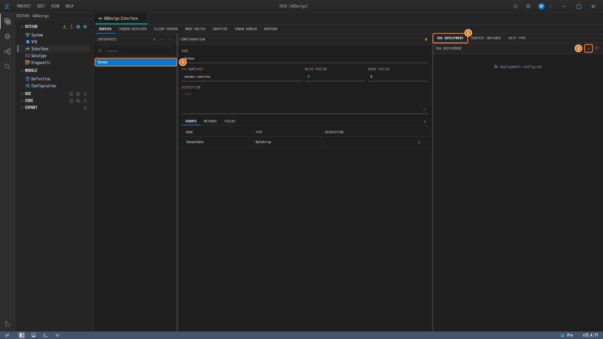
Figure 6-1. The Interface editor with the interface
Sensorselected. ① The selectedSensorrow in the list, ② the active SOA DEPLOYMENT subtab, ③ the + button in the header (tooltipAdd Deployment). The body showsNo deployments configured.
If the DATA TYPE subtab of the right panel is active (as it remains after picking a type in chapter 5), click SOA DEPLOYMENT to return. The ⟳ button is not pressed in this chapter.
Adding the Deployment
-
Click the + button in the SOA DEPLOYMENT header. A popover shows the three items SOME/IP, DDS and IPC.
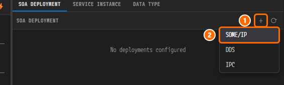
Figure 6-2. The popover after pressing the + button. ① The + button in the header, ② the SOME/IP item to click. DDS and IPC below it are not used.
-
Click SOME/IP. A collapsed card
SOME/IPSensorappears in the panel, and its summary showsSERVICE ID = 0x0001,VERSION 1.0,EVENTS = 1andMETHODS = 1. The tabAADesign:Interfacegets the modified mark ●.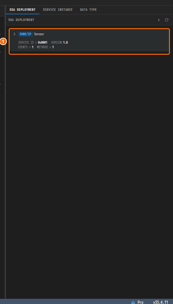
Figure 6-3. The deployment card just created. ① The collapsed card
SOME/IPSensor. The summary readsSERVICE ID = 0x0001VERSION 1.0EVENTS = 1METHODS = 1, and the service ID is still the default.
The deployment takes the name of the interface, Sensor. The EVENTS = 1 and METHODS = 1 in the summary mean that deployments for the event SensorData and the method Calculation of the interface were created automatically. IDs in the summary are always shown in hexadecimal.
Entering the Service ID
-
Click the card header
SOME/IPSensorto expand the card. You see the fields NAMESensor, SERVICE ID1(with a DEC / HEX toggle to the right of the label, DEC active), MAJOR VERSION1and MINOR VERSION0, and the accordions EVENT DEPLOYMENTS, METHOD DEPLOYMENTS and EVENT GROUPS, all expanded. -
Change the value of the SERVICE ID field to
11and press theTabkey. -
Leave NAME, MAJOR VERSION and MINOR VERSION as they are. They already match the reference design.
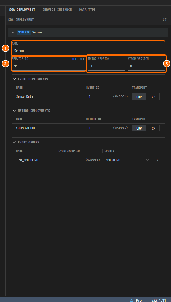
Figure 6-4. The deployment card with the service ID entered. ① NAME =
Sensor, ② SERVICE ID =11(DEC active), ③ MAJOR VERSION =1and MINOR VERSION =0. Below them the three accordions are expanded, and the EVENT GROUPS row still has the default nameEG_SensorData.
You type the SERVICE ID in decimal in DEC mode. If you press HEX, the same value is shown as 0xB. When you collapse the card, the summary changes to SERVICE ID = 0x000B.
Checking the Event and Method Deployments
-
Look at the EVENT DEPLOYMENTS accordion. Under the column headers NAME, EVENT ID and TRANSPORT there is the row
SensorData; its EVENT ID is1with the display(0x8001), and in the TRANSPORT segment UDP / TCP the option UDP is selected. -
Look at the METHOD DEPLOYMENTS accordion. Under the column headers NAME, METHOD ID and TRANSPORT there is the row
Calculation; its METHOD ID is1with the display(0x0001), and TRANSPORT is UDP. -
Do not touch either row. They already match the reference design.
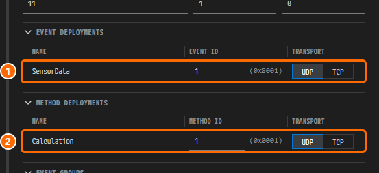
Figure 6-5. The automatically created event and method deployments. ① The row
SensorData1(0x8001)UDP in EVENT DEPLOYMENTS, ② the rowCalculation1(0x0001)UDP in METHOD DEPLOYMENTS.
Note. The
(0x8001)in the event row only shows the form SOME/IP uses when transmitting a notification event (0x8000plus the event ID). The event ID in the model and in the ARXML is1.
Renaming the Event Group
-
Look at the EVENT GROUPS accordion. Under the column headers NAME, EVENTGROUP ID and EVENTS there is the row
EG_SensorData; its EVENTGROUP ID is1with the display(0x0001), and EVENTS isSensorData. There is a + button to the right of the title (visible only while the mouse is over the title row) and a × button at the end of the row. -
Change the value of the NAME field in the row to
Eventgroup_SensorDataand press theTabkey. -
Leave EVENTGROUP ID
1and EVENTSSensorDataas they are.
Figure 6-6. The renamed EVENT GROUPS row. ① NAME =
Eventgroup_SensorData, ② EVENTGROUP ID =1(display(0x0001)), ③ EVENTS =SensorData. The NAME cell shows only as much of the name as its width allows, hereEventgroup_SensorDatwithout the last letter; the value is the wholeEventgroup_SensorData.
An event group is generated automatically for each event, with the name prefixed by EG_. The event group in the reference design is named Eventgroup_SensorData, so only the name is changed. The + and × buttons and the EVENTS dropdown are not used.
Adding the Service Instances
Adding One Provider and Two Consumers
-
Move the mouse over the header
SOME/IPSensorof the deployment card. At the right end of the header, the + button (tooltipAdd service instance) and the − button (tooltipRemove deployment) appear. Both buttons are visible only while the mouse is over the header. -
Click the + button. A popover shows the two items Provider and Consumer.
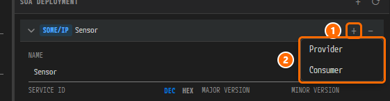
Figure 6-7. The popover after pressing the + button in the card header. ① The + button revealed by hovering, ② the Provider and Consumer items in the popover.
-
Click Provider. One provider instance is created.
-
Click the + button in the header again and click Consumer. Repeat once more so that there are two consumer instances.
-
Click the card header to collapse the card. Together with
SERVICE ID = 0x000BVERSION 1.0EVENTS = 1METHODS = 1, the summary now shows the rowPProvider_Sensor_10x0001under SERVICE PROVIDERS, and the rowsCConsumer_Sensor_10xFFFF (ANY)andCConsumer_Sensor_20xFFFF (ANY)under SERVICE CONSUMERS.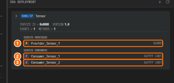
Figure 6-8. The deployment card collapsed after creating three instances. ① The row
PProvider_Sensor_10x0001under SERVICE PROVIDERS, ② the rowCConsumer_Sensor_10xFFFF (ANY)under SERVICE CONSUMERS, ③ the rowCConsumer_Sensor_20xFFFF (ANY). The service ID in the summary has changed to0x000B.
Instance names such as Provider_Sensor_1, Consumer_Sensor_1 and Consumer_Sensor_2 are generated automatically from the role, the service name and a number. The default instance ID of a provider is 1 (0x0001), and the default required instance ID of a consumer is ANY (0xFFFF). Clicking an instance row in the summary switches the right panel to the SERVICE INSTANCE subtab and expands the card of that instance.
Configuring the Provider Provider_Sensor
Entering the Name
- Click the row
PProvider_Sensor_1in the summary. The right panel switches to the SERVICE INSTANCE subtab. Its title is SERVICE INSTANCES with a + button (tooltipAdd service instance) at the right end. You see three cards:SOME/IP[P]Provider_Sensor_1(expanded),SOME/IP[C]Consumer_Sensor_1andSOME/IP[C]Consumer_Sensor_2(collapsed, summaryINSTANCE ID = ANY,SERVICE = Sensor). - Change the value of the NAME field of the provider card to
Provider_Sensorand press theTabkey. The card header follows every character you type. - Leave INSTANCE ID
1as it is.
NAME is applied character by character. The first time you click Sensor again after renaming, this card comes back collapsed; in that case click the header SOME/IP [P] Provider_Sensor to expand it again. It is easiest to enter the SD values after you have finished renaming.
Entering the SD SERVER CONFIG
-
Click the SD SERVER CONFIG accordion to expand it. Eight fields appear in two columns: INITIAL DELAY MIN
10 ms, INITIAL DELAY MAX100 ms, REPETITION BASE DELAY200 ms, REPETITION MAX3, OFFER CYCLIC DELAY500 ms, TTL0xFFFFFF(with a DEC / HEX toggle to the right of the label, HEX active), REQUEST RESPONSE DELAY MIN0 sand REQUEST RESPONSE DELAY MAX0 s. -
In the unit selector of INITIAL DELAY MIN pick
us, then change the value to10and press theTabkey. ClickSensorin the INTERFACES list on the left again. If the card is collapsed, click its header and then SD SERVER CONFIG to expand both again. -
Pick
usas the unit of INITIAL DELAY MAX, change the value to100and press theTabkey. ClickSensoragain. -
Pick
usas the unit of REPETITION BASE DELAY, change the value to200and press theTabkey. ClickSensoragain. -
For OFFER CYCLIC DELAY keep the unit
ms, change the value to1and press theTabkey. ClickSensoragain. -
Leave REPETITION MAX
3, TTL0xFFFFFF, REQUEST RESPONSE DELAY MIN0 sand REQUEST RESPONSE DELAY MAX0 sas they are.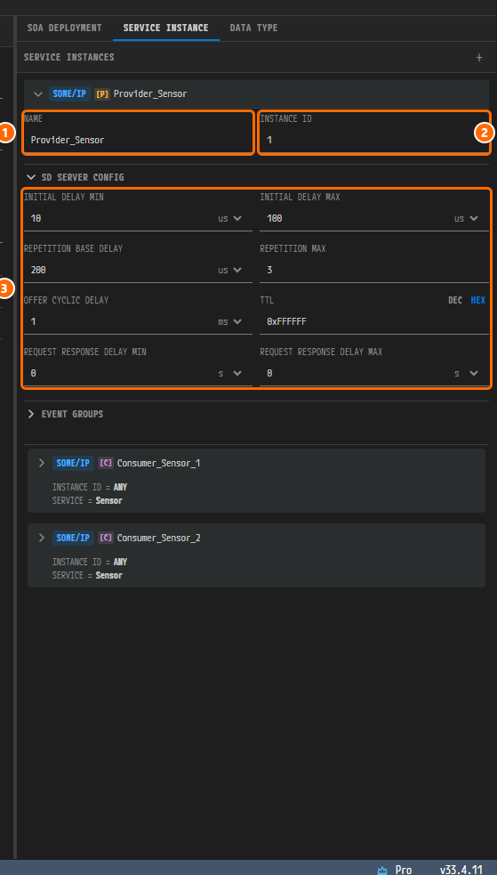
Figure 6-9. The finished provider card. ① NAME =
Provider_Sensor, ② INSTANCE ID =1, ③ the eight fields of SD SERVER CONFIG —10 us,100 us,200 us,3,1 ms,0xFFFFFF,0 s,0 s. EVENT GROUPS below is collapsed, and under it the consumer cardsConsumer_Sensor_1andConsumer_Sensor_2are shown collapsed.
Note. A time field is stored in seconds and displayed in whichever of
ns,us,msandsreads best. Changing the unit selector only converts the displayed number and does not change the stored value, so always pick the unit first and then type the value.10 usis stored as0.00001seconds and1 msas0.001seconds. The TTL value0xFFFFFFis16777215in decimal and matches the reference design.
Checking the EVENT GROUPS
-
Click the EVENT GROUPS accordion to expand it. Under the column headers EVENT GROUP and MULTICAST THRESHOLD there is the row
Eventgroup_SensorData0. -
Click the row to expand it. You see the MULTICAST THRESHOLD segment (UNICAST selected, ALWAYS MULTICAST and MULTICAST AT N on the right), IPV4 MULTICAST (hint
IPv4 Address), IPV6 MULTICAST (hintIPv6 Address), MULTICAST UDP PORT0, RESP DELAY MIN0 sand RESP DELAY MAX0 s. -
Leave everything at its default. The MULTICAST THRESHOLD of the reference design is
0(UNICAST).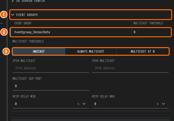
Figure 6-10. The EVENT GROUPS of the provider card. ① The expanded EVENT GROUPS accordion, ② the row
Eventgroup_SensorData0, ③ the MULTICAST THRESHOLD segment (UNICAST selected). The fields below are IPV4 MULTICAST, IPV6 MULTICAST (empty), MULTICAST UDP PORT0, RESP DELAY MIN0 sand RESP DELAY MAX0 s.
Configuring the Consumers Actuator_Sensor and Fusion_Sensor
Configuring the First Consumer Actuator_Sensor
The first of the two consumers is shown as a procedure. As with the provider, rename first and then enter the SD values.
-
Click the card header
SOME/IP[C]Consumer_Sensor_1to expand it. You see the fields NAMEConsumer_Sensor_1and REQUIRED INSTANCE IDANY, and the accordions SD CLIENT CONFIG and EVENT GROUPS (both collapsed). -
Change the value of the NAME field to
Actuator_Sensorand press theTabkey. -
Leave REQUIRED INSTANCE ID
ANYas it is. -
Click the SD CLIENT CONFIG accordion to expand it. Five fields appear: INITIAL DELAY MIN
10 ms, INITIAL DELAY MAX100 ms, REPETITION BASE DELAY200 ms, REPETITION MAX3and TTL0xFFFFFF. -
Pick
usas the unit of INITIAL DELAY MIN, change the value to10and press theTabkey. ClickSensorin the list on the left again. If the card is collapsed, expand it and its SD CLIENT CONFIG again. -
Pick
usas the unit of INITIAL DELAY MAX, change the value to100and press theTabkey. ClickSensoragain. -
Pick
usas the unit of REPETITION BASE DELAY, change the value to200and press theTabkey. ClickSensoragain. -
Leave REPETITION MAX
3and TTL0xFFFFFFas they are.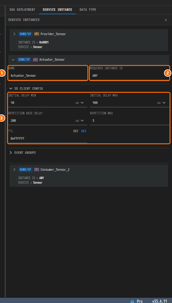
Figure 6-11. The finished first consumer card. ① NAME =
Actuator_Sensor, ② REQUIRED INSTANCE ID =ANY, ③ the five fields of SD CLIENT CONFIG —10 us,100 us,200 us,3,0xFFFFFF. The provider card above is collapsed and shows the summaryINSTANCE ID = 0x0001SERVICE = Sensor; the second consumer card below still has the default nameConsumer_Sensor_2.
If you expand the EVENT GROUPS accordion of a consumer card, there is the row Eventgroup_SensorData 0xFFFFFF under the column headers EVENT GROUP and TTL, and expanding the row shows TTL (DEC / HEX), RESP DELAY MIN, RESP DELAY MAX, RETRY DELAY and RETRY MAX. They are not touched in this chapter.
Configuring the Second Consumer Fusion_Sensor
Configure the second consumer the same way. Only the name differs.
- Click the card header
SOME/IP[C]Consumer_Sensor_2to expand it. - Change the value of the NAME field to
Fusion_Sensorand press theTabkey. Leave REQUIRED INSTANCE IDANYas it is. - Expand SD CLIENT CONFIG and enter INITIAL DELAY MIN
10 us, INITIAL DELAY MAX100 usand REPETITION BASE DELAY200 usone at a time. After each value press theTabkey and clickSensoragain. Leave REPETITION MAX3and TTL0xFFFFFFas they are.
Saving
-
Click an empty spot in the tab bar to leave the input field.
-
Press
Ctrl+S. The modified mark ● on the tabAADesign:Interfacedisappears anddesign/SERVICE.io.modelis created. -
In the SERVICE INSTANCE panel, click the header of each card that is still expanded to collapse it. The three cards are shown in the order
SOME/IP[P]Provider_Sensor(summaryINSTANCE ID = 0x0001,SERVICE = Sensor),SOME/IP[C]Actuator_SensorandSOME/IP[C]Fusion_Sensor(summaryINSTANCE ID = ANY,SERVICE = Sensor).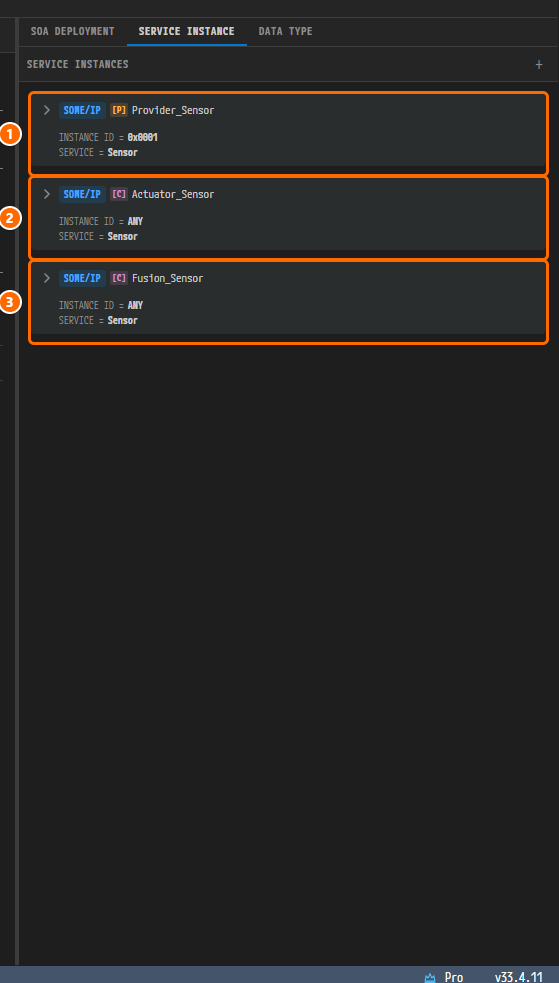
Figure 6-12. The SERVICE INSTANCE panel after saving. ① The card
SOME/IP[P]Provider_Sensor(INSTANCE ID = 0x0001,SERVICE = Sensor), ② the cardSOME/IP[C]Actuator_Sensor(INSTANCE ID = ANY), ③ the cardSOME/IP[C]Fusion_Sensor(INSTANCE ID = ANY).
The saved design/SERVICE.io.model looks like this (date fields and empty collections are abbreviated, and Fusion_Sensor differs from Actuator_Sensor only by name).
{
  "$schema": "https://autosar.io/schemas/service.schema.json",
  "version": "2.0.0",
  "metadata": { "name": "Service Model" },
  "someip-service-interface-deployments": [
    {
      "name": "Sensor", "interface": "Sensor", "service-id": 11,
      "major-version": 1, "minor-version": 0,
      "event-deployments":  [ { "event": "SensorData",   "event-id": 1,  "transport": "udp" } ],
      "method-deployments": [ { "method": "Calculation", "method-id": 1, "transport": "udp" } ],
      "field-deployments": [],
      "event-groups": [ { "id": 1, "name": "Eventgroup_SensorData", "events": [ "SensorData" ] } ]
    }
  ],
  "service-providers": { "someip": [
    {
      "name": "Provider_Sensor", "service": "Sensor", "instance-id": 1,
      "sd-server-config": {
        "initial-delay-min": 0.00001, "initial-delay-max": 0.0001,
        "repetition-base-delay": 0.0002, "repetition-max": 3,
        "offer-cyclic-delay": 0.001,
        "request-response-delay-min": 0, "request-response-delay-max": 0,
        "ttl": 16777215
      },
      "provided-event-groups": [ { "event-group": "Eventgroup_SensorData", "multicast-threshold": 0 } ]
    }
  ] },
  "service-consumers": { "someip": [
    {
      "name": "Actuator_Sensor", "service": "Sensor", "required-instance-id": 65535,
      "sd-client-config": {
        "initial-delay-min": 0.00001, "initial-delay-max": 0.0001,
        "repetition-base-delay": 0.0002, "repetition-max": 3, "ttl": 16777215
      },
      "required-event-groups": [ { "event-group": "Eventgroup_SensorData" } ]
    },
    { "name": "Fusion_Sensor" }
  ] }
}
The SERVICE ID 11 is stored as "service-id": 11, TRANSPORT UDP as "transport": "udp", the on-screen 10 us as 0.00001, and REQUIRED INSTANCE ID ANY as 65535. Besides the keys shown above, an event group row also stores the defaults of its detail fields such as IPV4 MULTICAST.
This save also creates SIGNAL.io.model in design/ and adds Sensor_SR and Sensor_CS to INTERFACE.io.model. These are Classic Platform signals and interfaces that the Interface editor derives automatically from the SOME/IP deployment; they are not part of the design this tutorial builds by hand. IVC.io.model does not change.
Viewing the Validation Result
-
Look at the V icon in the footer at the bottom of the window, the fifth icon from the left. It carries no badge.
-
Look at the VALIDATION panel. If it is closed, click the V icon in the footer.

Figure 6-13. The VALIDATION panel after saving. The header carries no badge, and under the column headers ELEMENT TYPE, NAME, DESCRIPTION and CONSTR there is the single line
No validation issues..
The panel has no row for the deployment Sensor, the event group Eventgroup_SensorData or the three instances created in this chapter, and none for the PDUs of the derived signals that the save added to SIGNAL.io.model (Sensor_SensorData_PDU, Sensor_Calculation_Call_PDU and Sensor_Calculation_Return_PDU).
Why Is It Designed This Way?
- The deployment keeps the name
Sensor. TheSOMEIP-SERVICE-INTERFACE-DEPLOYMENTof the reference design is namedSensorwithSERVICE-INTERFACE-ID11and version1/0. The editor names the deployment after the interface, so only the SERVICE ID is entered. - The event and method deployments need no input. In the reference design, the
SOMEIP-EVENT-DEPLOYMENTSensorDatahasEVENT-ID1/UDPand theSOMEIP-METHOD-DEPLOYMENTCalculationhasMETHOD-ID1/UDP, and the values the editor generates are already those. - The event group must be named
Eventgroup_SensorData. That is the name of theSOMEIP-EVENT-GROUPin the reference design, and ARXML Export also uses the naming ruleEventgroup_{event}when it looks up the events of a group. Keeping the default nameEG_SensorDatawould make the exported name differ from the reference design. - The three instance names are the
SHORT-NAMEs of the reference design. They are thePROVIDED-SOMEIP-SERVICE-INSTANCEProvider_Sensor(SERVICE-INSTANCE-ID1) and theREQUIRED-SOMEIP-SERVICE-INSTANCEsActuator_SensorandFusion_Sensor(REQUIRED-SERVICE-INSTANCE-IDANY). For INSTANCE ID1and REQUIRED INSTANCE IDANY, the defaults are already the reference design values. - The SD timing is one thousandth of the defaults. The
SdServerConfig_Provider_Sensorof the reference design hasINITIAL-DELAY-MIN0.00001,MAX0.0001,INITIAL-REPETITIONS-BASE-DELAY0.0002,INITIAL-REPETITIONS-MAX3,OFFER-CYCLIC-DELAY0.001,REQUEST-RESPONSE-DELAY0/0andSERVICE-OFFER-TIME-TO-LIVE16777215;SdClientConfig_Actuator_SensorandSdClientConfig_Fusion_Sensorhave0.00001/0.0001/0.0002/3/SERVICE-FIND-TIME-TO-LIVE16777215. These differ from the editor defaults10 ms,100 ms,200 msand500 ms, so four time fields (three for a consumer) are changed. The namesSdServerConfig_{instance}/SdClientConfig_{instance}of the SD configuration elements are assigned by the exporter. - The
MULTICAST-THRESHOLDof the provider event group is0. That is the value of theSOMEIP-PROVIDED-EVENT-GROUPin the reference design, and the editor default UNICAST is that value. - The consumers'
REQUIRED-MINOR-VERSIONANYandVERSION-DRIVEN-FIND-BEHAVIORare not entered. The editor has no field for them and the exporter writes fixed values. - The
SOMEIP-SERVICE-INSTANCE-TO-MACHINE-MAPPINGthat binds the instances to the machine is not created in this chapter. It is created with the System editor in Binding Service Instances to the Connector.
Checklist
- The SOA DEPLOYMENT panel has one card
SOME/IPSensor, and its collapsed summary readsSERVICE ID = 0x000BVERSION 1.0EVENTS = 1METHODS = 1. - The summary lists
PProvider_Sensor0x0001under SERVICE PROVIDERS, andCActuator_Sensor0xFFFF (ANY)andCFusion_Sensor0xFFFF (ANY)under SERVICE CONSUMERS. - When the card is expanded, SERVICE ID is
11, MAJOR VERSION1, MINOR VERSION0, and there areSensorData1UDP in EVENT DEPLOYMENTS,Calculation1UDP in METHOD DEPLOYMENTS, andEventgroup_SensorData1SensorDatain EVENT GROUPS. - The SERVICE INSTANCE panel has the three cards
[P]Provider_Sensor,[C]Actuator_Sensorand[C]Fusion_Sensor. -
Provider_Sensorhas INSTANCE ID1and SD SERVER CONFIG10 us,100 us,200 us,3,1 ms,0xFFFFFF,0 s,0 s. -
Actuator_SensorandFusion_Sensorhave REQUIRED INSTANCE IDANYand SD CLIENT CONFIG10 us,100 us,200 us,3,0xFFFFFF. - The tab
AADesign:Interfacehas no modified mark ● and the filedesign/SERVICE.io.modelexists. - The VALIDATION panel shows
No validation issues.and the header carries no badge.
Next Step
In Binding Service Instances to the Connector, you bind the instances Provider_Sensor, Actuator_Sensor and Fusion_Sensor to the Ethernet connector in the System editor and assign their UDP ports.