Creating the Project and the HPC Machine
What You Will Do
In this chapter you start from a PAIO window with no project open and build the skeleton of the Adaptive Application design.
You create the project AADesign, place one HPC node in the System editor and rename it to Ecu, then create the composition HPC in the VFB editor and map it onto that node.
Finally you open the Machine Configuration dialog through the machine icon attached to the composition, look through its four tabs, and save it.
When you finish this chapter, design/ holds seven files and the VALIDATION panel shows one error (constr_10641). That one finding is expected; you fix it in Machine Configuration.
Before You Begin
- PAIO must be installed and ready to run.
- Start from a PAIO window with no project open. The title bar reads
PAIO, the EDITOR view on the left showsNo project open, and the Welcome tab (Welcome to PAIO) is open. If PAIO opens a project you worked on before, choose PROJECT › New Window to get such a window. - This tutorial does not depend on any other tutorial or example project. Follow it from this chapter onward.
Apart from the folder you choose for the project, you type only three values in this chapter. These names are used as they are in every later chapter, so do not change them.
| Element | Value to type | Where |
|---|---|---|
| Project name | AADesign | New Project dialog |
| HPC node name | Ecu | System editor property panel NAME |
| Composition name and prototype name | HPC (twice) | VFB editor property panel NAME and AS PROTOTYPE |
Note. The node name
Ecugoes into the machine file name (Ecu.machine.io.model), the Ethernet endpoint names you create in later chapters (Ecu_eth0_UDP_20001and so on), and the DLT ECU path. The composition nameHPCis used in the system mapping and in the title of the Machine Configuration dialog.
Creating a New Project
Opening New Project from the Project Menu
-
Click PROJECT in the menu at the top of the window.
-
Click New Project... in the dropdown. It has no shortcut. The New Project button on the Welcome tab opens the same dialog.
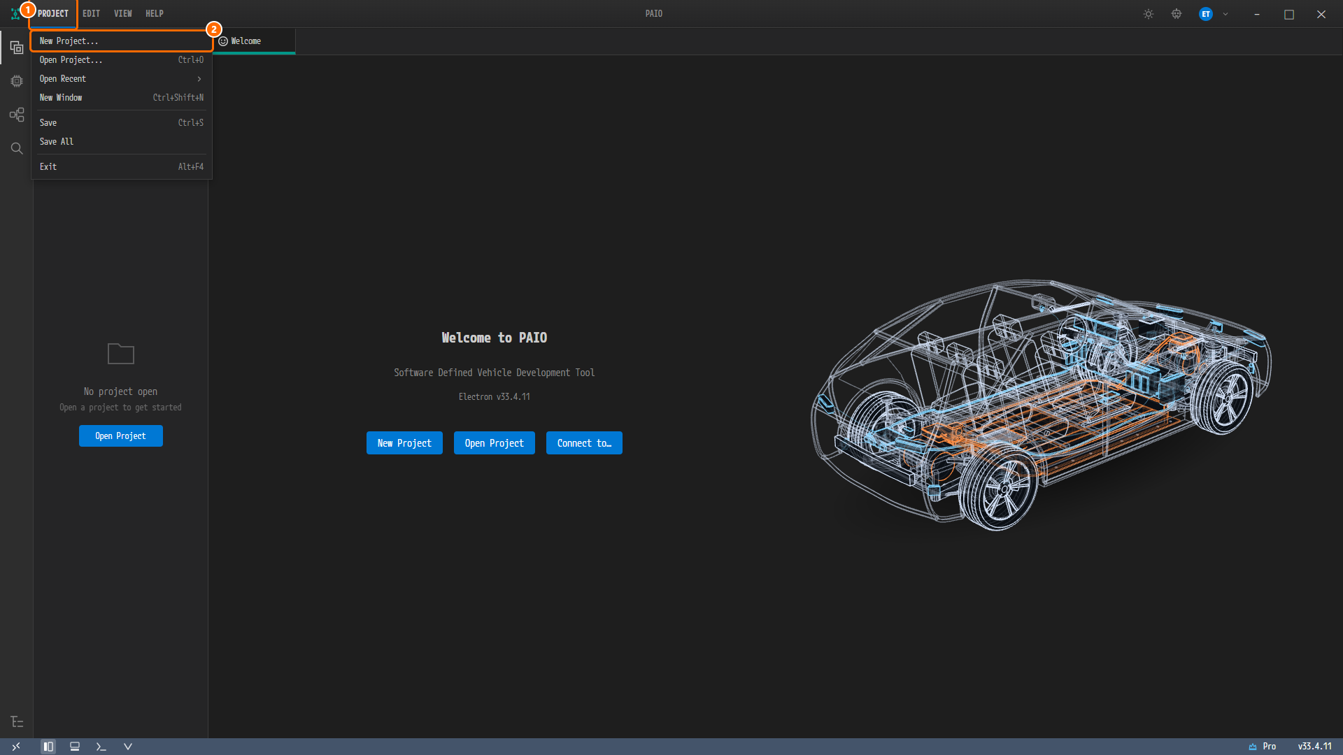
Figure 1-1. The PROJECT menu opened in a window with no project open. ① The PROJECT menu button, ② the New Project... item. The same dropdown holds Save and Save All, which you use several times in this chapter. Behind the menu, the EDITOR view shows
No project openand the Welcome tab is open.
Entering the Name and Creating
-
In the New Project dialog, type
AADesigninto Name. -
Set Location to the folder that will hold the project: type its path, or click Browse… and pick the folder. PAIO creates the project folder
AADesigninside it, and the line below the fields shows that path asThe project will be created in …\AADesign. Create stays disabled until both Name and Location are set. -
Click the Create button.
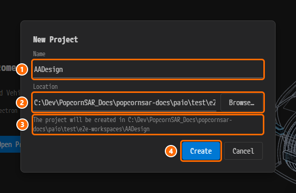
Figure 1-2. The New Project dialog. ① Name with
AADesigntyped in, ② Location and the Browse… button, ③ the lineThe project will be created in …that names the new project folder, ④ the Create button. The folder in the figure is only an example; use a folder of your own.
Touring the EDITOR View
-
Confirm that the same window has entered the new project: the title bar reads
PAIO [AADesign]and the view on the left is headedEDITOR: AADesign. -
Confirm that DESIGN and MODULE are open in the EDITOR view. DESIGN lists System, VFB, Interface, DataType, Diagnostic, and MODULE lists Definition and Configuration.
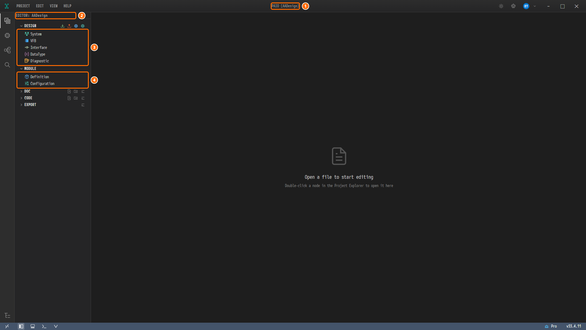
Figure 1-3. The window after Create. ① The title bar
PAIO [AADesign], ② the view headerEDITOR: AADesign, ③ the DESIGN rows System, VFB, Interface, DataType, Diagnostic, ④ the MODULE rows Definition, Configuration. The Welcome tab closed when the window entered the project, so the editor area has no tab open yet.
The items of the EDITOR view are as follows.
| Item | Role | In this tutorial |
|---|---|---|
| DESIGN › System | Vehicle network topology editor (nodes, connectors, clusters) | This chapter, chapter 3 |
| DESIGN › VFB | Software composition and Adaptive Application editor | This chapter, chapter 8 onward |
| DESIGN › Interface | Service interface editor | Chapter 5 |
| DESIGN › DataType | Data type editor | Chapter 4 |
| DESIGN › Diagnostic | Diagnostic editor | Not used |
| MODULE › Definition, Configuration | Module definitions and configurations | Not used |
| DOC | Project documents | Not used |
| CODE, EXPORT | Code and export output | EXPORT in chapter 13 |
Right after the project is created, design/ holds three files: IVC.io.model, SYSTEM.io.model, VFB.io.model. By the end of this chapter there are seven.
Creating the HPC Node
Opening the System Editor
- In the EDITOR view on the left, click System under DESIGN. A single click opens the System editor.
- Confirm that the tab
AADesign:Systemopened and thatSystemis shown in the upper-left corner of the canvas. The canvas is empty.
Adding an HPC to the Canvas
-
Right-click an empty spot on the canvas. The menu shows two items: Add ECU and Add HPC.
-
Click Add HPC.
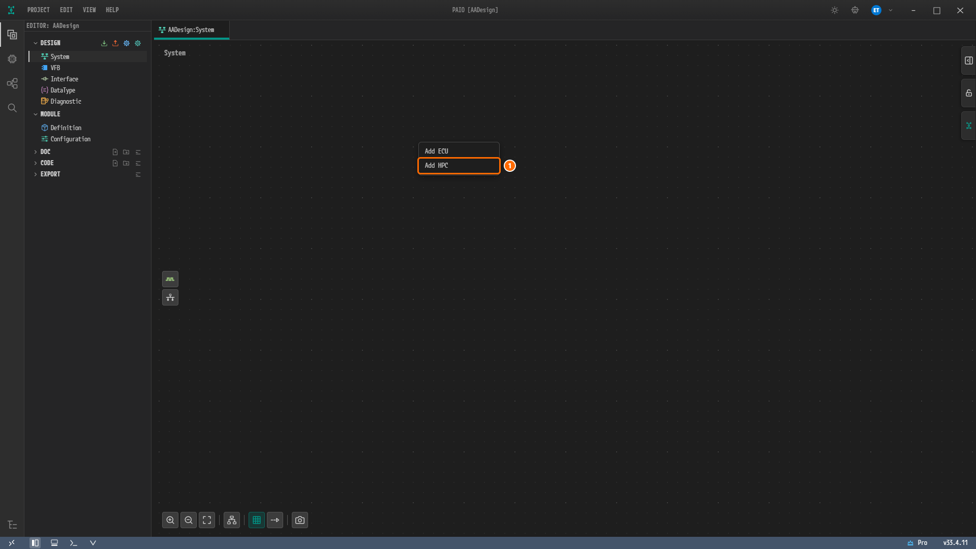
Figure 1-4. The right-click menu of the empty System editor canvas. ① Add HPC.
-
The node
HPC_0appears on the canvas. A blue dot (the modified mark) appears next to the tab title. -
Click the node header
HPC_0. A property panel titled HPC opens on the right.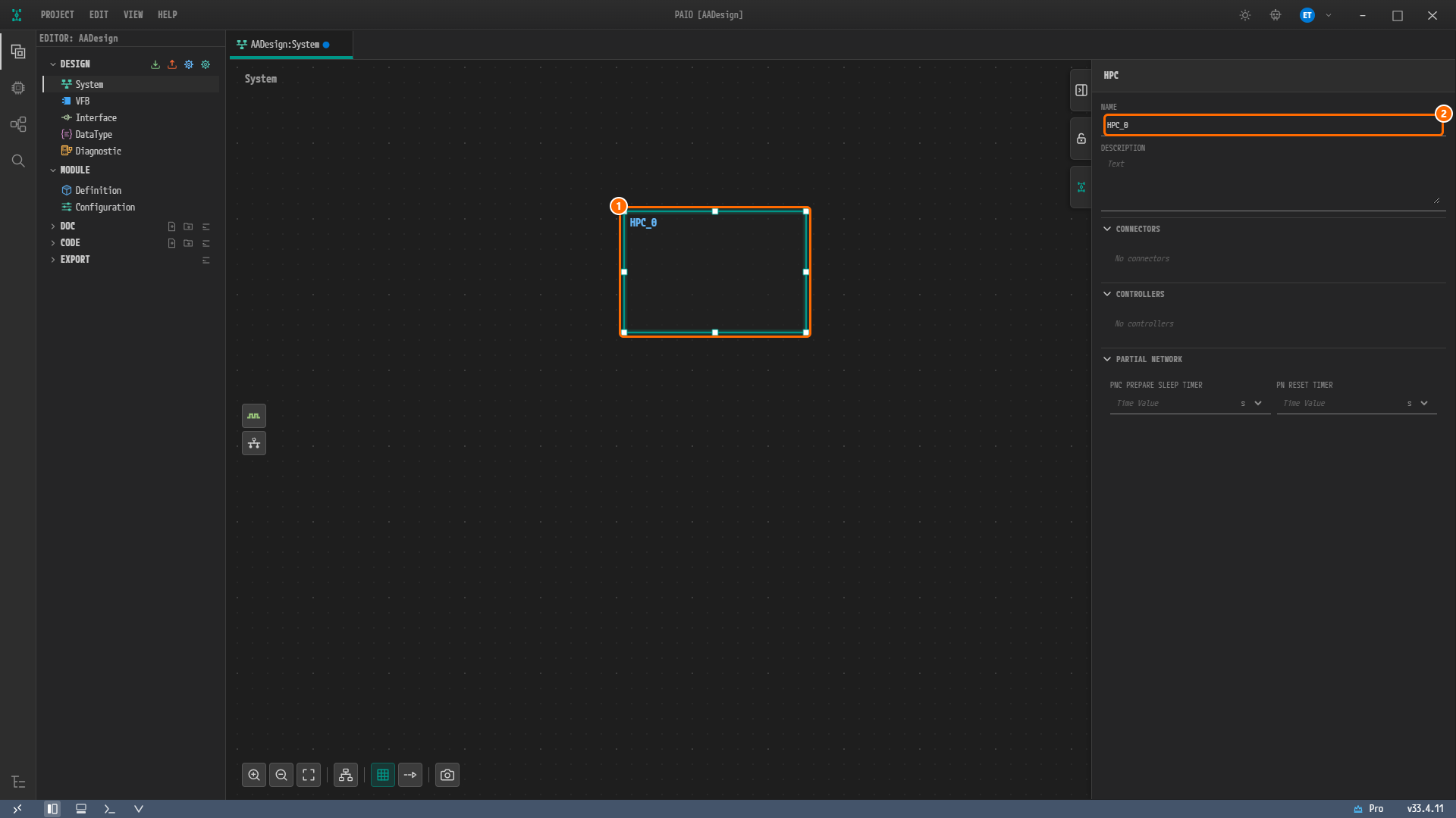
Figure 1-5. The node you just created. ① The selected node
HPC_0, ② the NAME field of the property panel. Below it are the DESCRIPTION, CONNECTORS (No connectors), CONTROLLERS (No controllers) and PARTIAL NETWORK sections. In this chapter you change NAME only.
Renaming the Node to Ecu
-
Delete
HPC_0in the NAME field of the property panel and typeEcu. -
Press the
Tabkey. The node header on the canvas changes toEcu. -
Press
Ctrl+Sto save. The blue dot on the tab title disappears.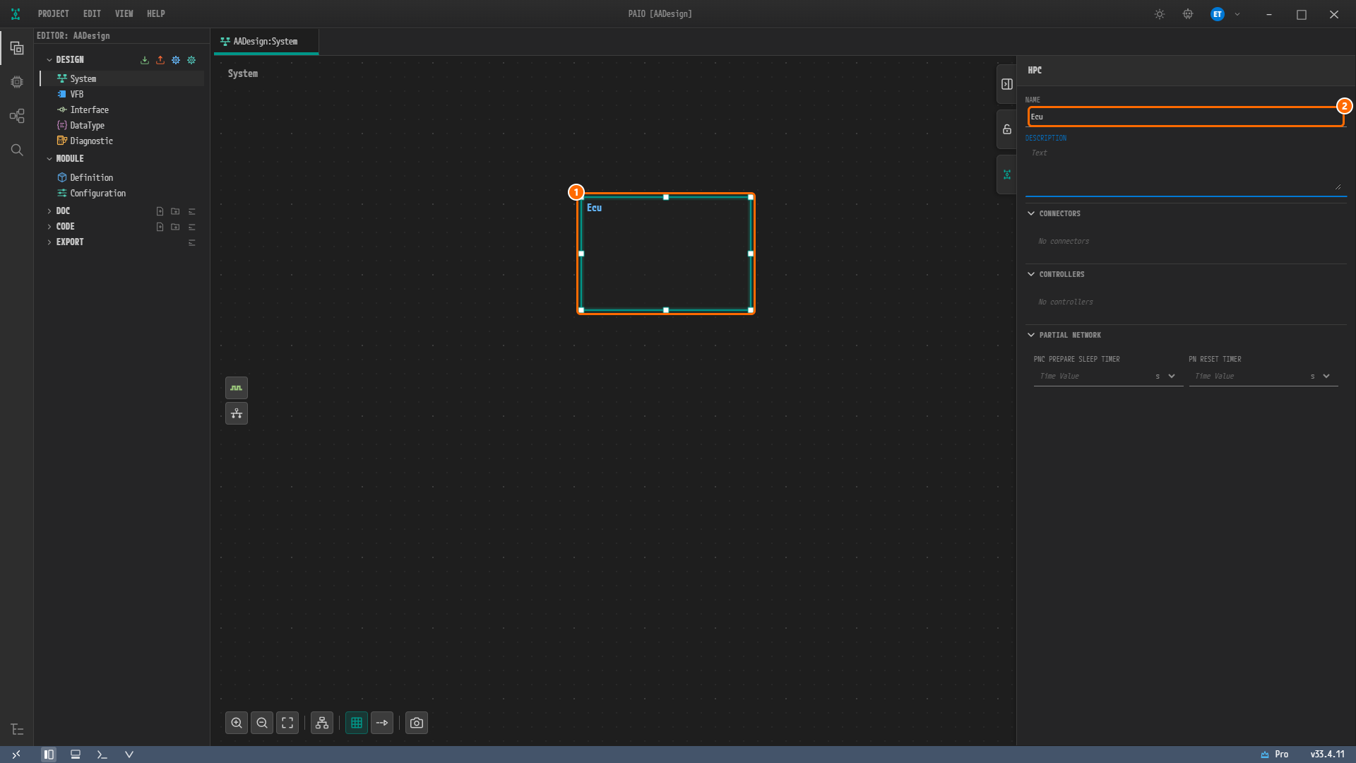
Figure 1-6. The System editor after saving. ① The node whose header now reads
Ecu, ②Ecuin the NAME field. The tabAADesign:Systemcarries no modified mark.
Creating the Composition HPC
The software composition that goes onto the node is created in the VFB editor.
Adding a Composition in the VFB Editor
-
In the EDITOR view, click VFB under DESIGN. The tab
AADesign:VFBopens. The canvas of the root compositionSystemis empty, and the property panel on the right is closed until you select an element. -
Right-click an empty spot on the canvas. The menu shows three items: Add Composition, Attach Composition, Add Interface Mapping.
-
Click Add Composition. The composition
Composition_0appears on the canvas.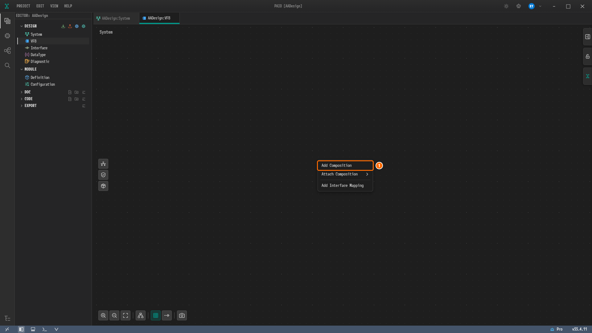
Figure 1-7. The right-click menu of the empty VFB root canvas. ① Add Composition. The tab bar holds both
AADesign:SystemandAADesign:VFB.
Renaming the Name and the Prototype Name to HPC
-
Click the new composition. A property panel titled COMPOSITION opens on the right.
-
Type
HPCinto the NAME field and press theTabkey. -
Type
HPCinto the AS PROTOTYPE field as well and press theTabkey. -
Press
Ctrl+Sto save, then click PROJECT › Save All.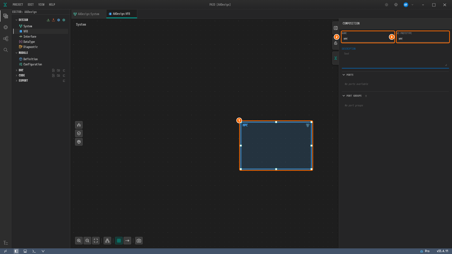
Figure 1-8. The renamed composition. ① The composition node
HPC, ② NAME =HPC, ③ AS PROTOTYPE =HPC. PORTS readsNo ports availableand PORT GROUPS readsNo port groups.
Caution. Changing NAME leaves AS PROTOTYPE at
Composition_0. You must typeHPCinto both fields so that the system mapping and the label on the root canvas readHPC.
Mapping the Composition onto the Node
Running SW Mapping in the System Editor
-
Click the tab
AADesign:Systemto return to the System editor. -
Right-click the empty body of the node
Ecu. The menu shows seven items: Add Connector, Add Controller, Add Ethernet Switch, Add Gateway, SW Mapping, Extract Machine, Delete. -
Hover over SW Mapping. The submenu shows HPC and New Composition.
-
Click HPC.
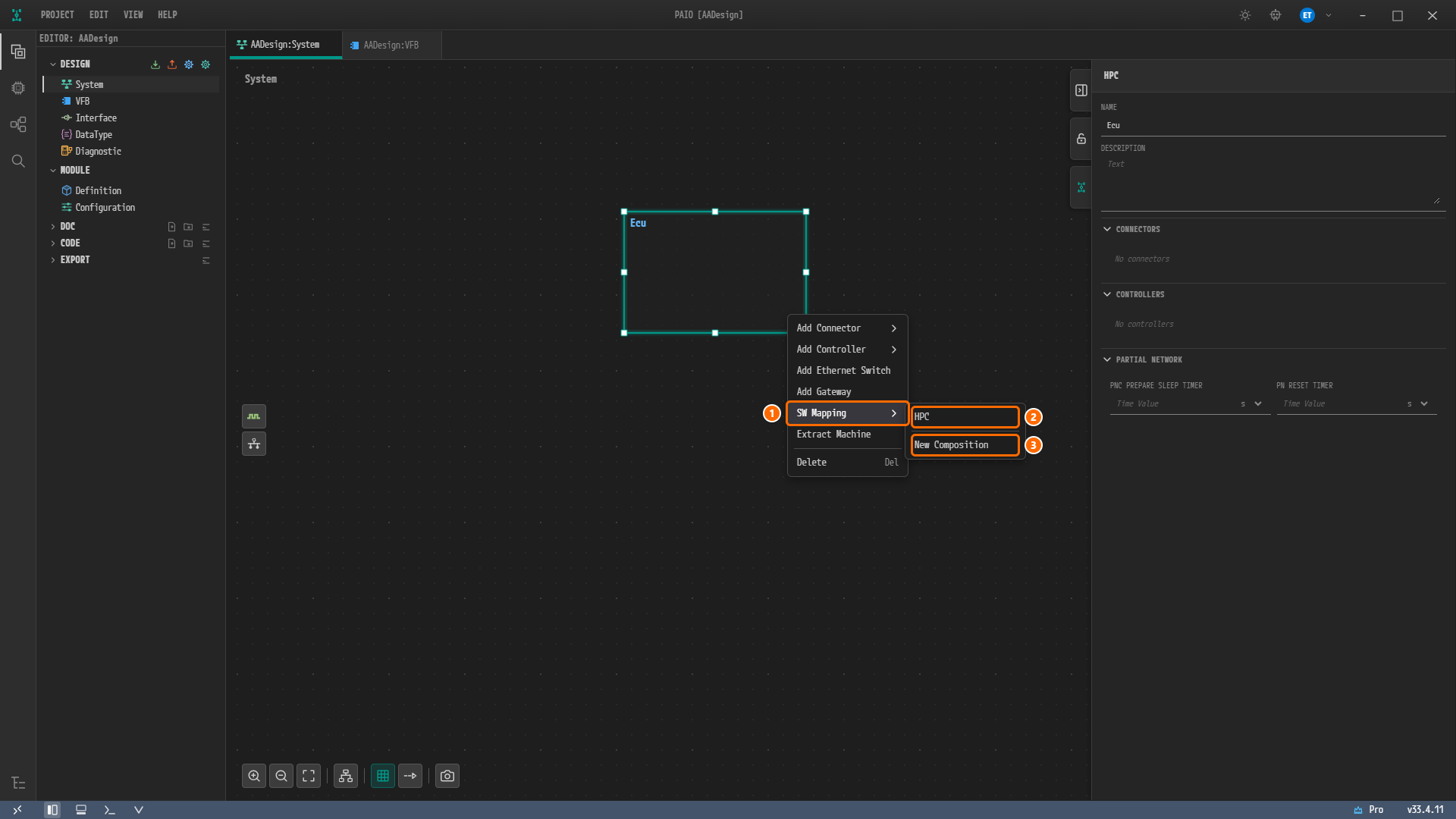
Figure 1-9. The right-click menu of the node
Ecu. ① SW Mapping, ② HPC in the submenu, ③ New Composition. In this tutorial you click ② and do not use ③. -
There is nothing to save: the click writes the mapping to
design/SYSTEM.io.modelat once, and no tab shows the modified mark. The node header on the canvas now readsEcu [HPC]; the name in brackets is the mapped composition.
Note. New Composition creates a new composition named after the node and maps it. Because the node is
Ecu, the composition would beEcutoo. This design keeps the nodeEcuand the compositionHPCapart, so you map theHPCyou created in the VFB with SW Mapping › HPC.
Checking the Mapping in the VFB Editor
-
Click the tab
AADesign:VFB. -
Confirm that the composition label on the root canvas changed to
HPC [Ecu]and that a machine icon shaped like three blue bars is attached to the right of the header. The name in brackets is the mapped HPC node.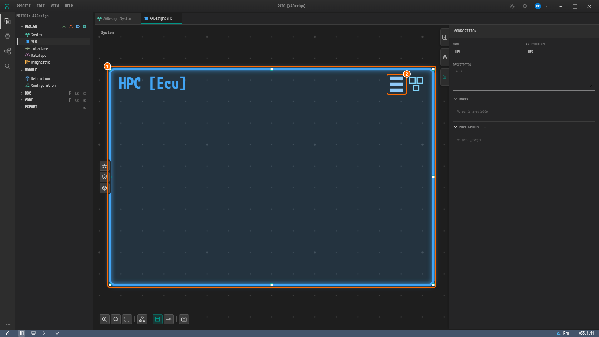
Figure 1-10. The VFB root canvas after the mapping. ① The composition
HPC [Ecu], ② the machine icon at the right of the header. NAME and AS PROTOTYPE in the property panel both readHPC.
Opening the Machine Configuration Dialog
Clicking the machine icon opens the Machine Configuration dialog. In this chapter you change no value: you look through the four tabs and save. When the dialog is opened for the first time, the function group MachineFG, the processor CPU and eleven modules are filled in as defaults, and pressing Ctrl+S inside the dialog is what writes those defaults into the machine file.
Opening the Dialog
- Click the × on the tab
AADesign:VFBto close the tab. - In the EDITOR view, click VFB under DESIGN again.
- Click the machine icon in the header of the composition
HPC [Ecu]. A dialog titled Machine Configuration [HPC] opens. The name in brackets is the composition name.
Caution. In a VFB tab that was already open before the mapping, the machine icon is visible but clicking it does not open the dialog. Close the tab and reopen it as in steps 1 and 2. You do not need to restart the application.
The MACHINE Tab
The dialog opens with the MACHINE tab selected.
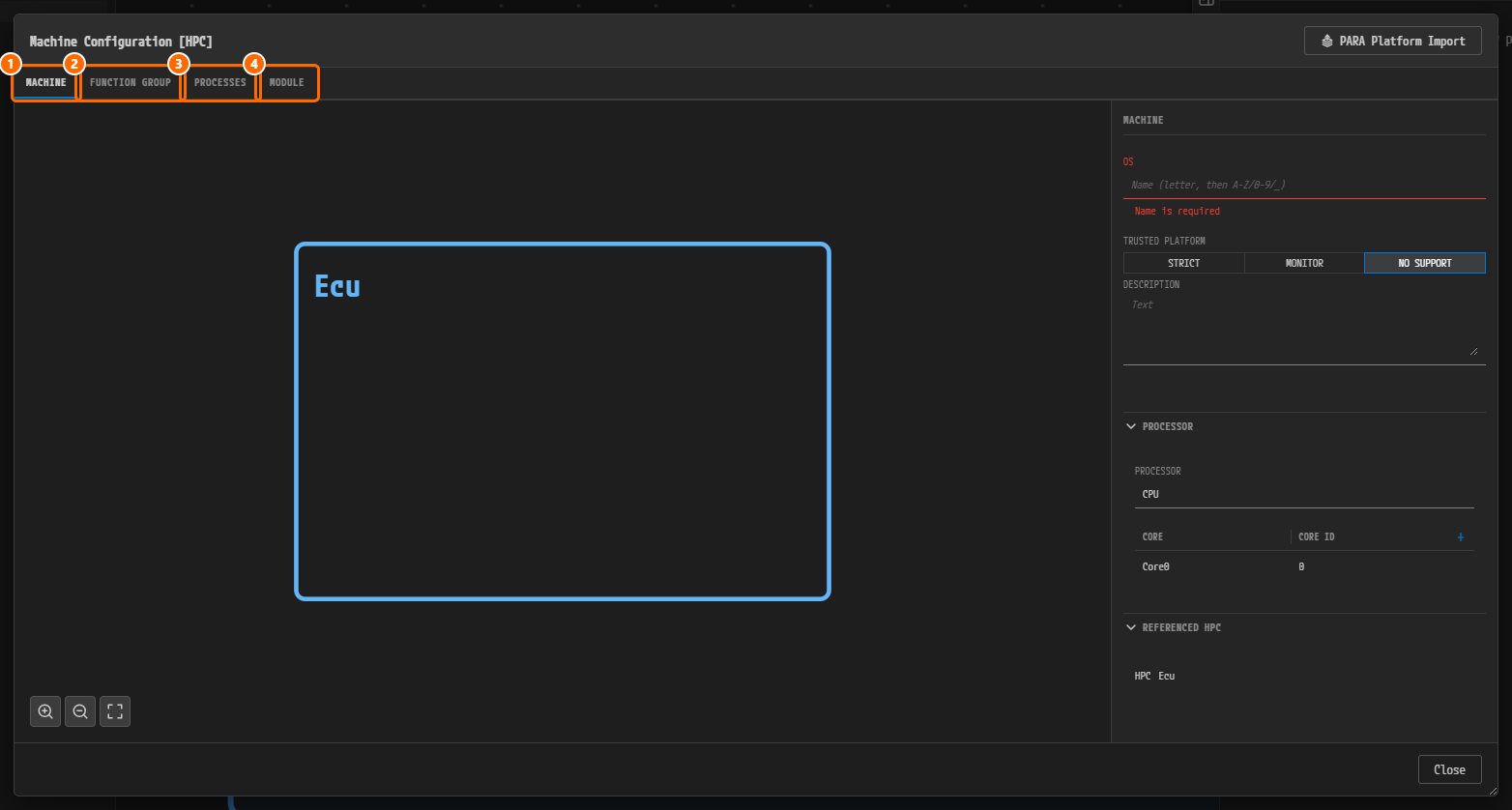
Figure 1-11. The Machine Configuration [HPC] dialog. ① MACHINE, ② FUNCTION GROUP, ③ PROCESSES, ④ MODULE tabs. The center canvas holds the machine box Ecu; the PARA Platform Import button is at the top right and the Close button at the bottom right.
The MACHINE panel on the right shows the following.
| Item | Current value | Notes |
|---|---|---|
| OS | Empty, with the red hint Name is required | Filled in Machine Configuration. This is expected for now |
| TRUSTED PLATFORM | NO SUPPORT (choices STRICT, MONITOR, NO SUPPORT) | Leave it |
| DESCRIPTION | Empty (hint Text) | Leave it |
| PROCESSOR › PROCESSOR | CPU | Default |
| PROCESSOR › CORE / CORE ID table | One row Core0 / 0, a + button (tooltip Add Core) | Cores are added in Machine Configuration |
| REFERENCED HPC | HPC Ecu | The HPC node mapped in the System editor |
The FUNCTION GROUP Tab
-
Click the FUNCTION GROUP tab.
-
Confirm that the FUNCTION GROUPS list on the left holds one entry,
MachineFG, and that it is selected.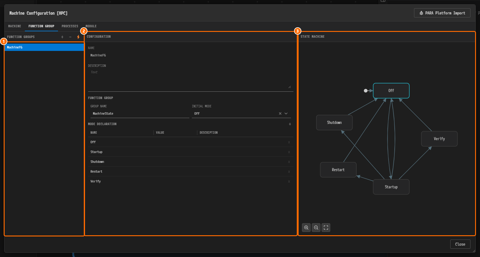
Figure 1-12. The FUNCTION GROUP tab. ① The FUNCTION GROUPS list (+, −, lightning icon), ② the CONFIGURATION panel, ③ the STATE MACHINE diagram.
The values in the center CONFIGURATION panel are as follows. All are defaults, and this tutorial uses this function group as it is.
| Item | Value |
|---|---|
| NAME | MachineFG |
| FUNCTION GROUP › GROUP NAME | MachineState |
| FUNCTION GROUP › INITIAL MODE | Off |
| MODE DECLARATION table (NAME / VALUE / DESCRIPTION) | Off, Startup, Shutdown, Restart, Verify (every VALUE empty) |
The STATE MACHINE diagram on the right draws the five states with transition arrows, and the initial-state marker is attached to Off.
The PROCESSES Tab
-
Click the PROCESSES tab.
-
Confirm that the body shows only the line
No Adaptive Application processes found in this Composition. No Adaptive Application exists yet, so this is expected.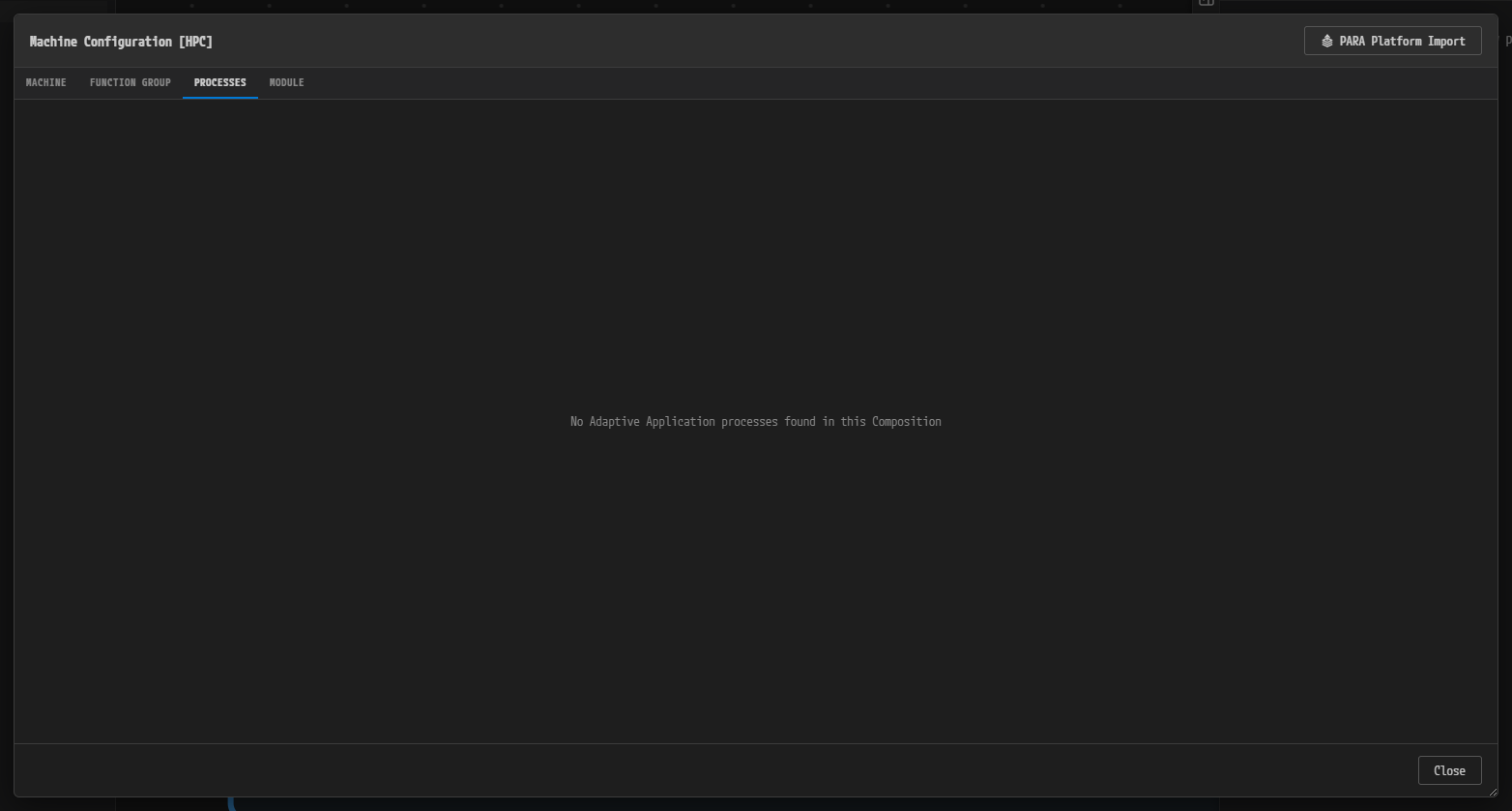
Figure 1-13. The empty PROCESSES tab. Processes appear in Executables and Processes.
The MODULE Tab
-
Click the MODULE tab.
-
Confirm that the MODULES list on the left holds eleven modules and that the first entry, Log and Trace, is selected.
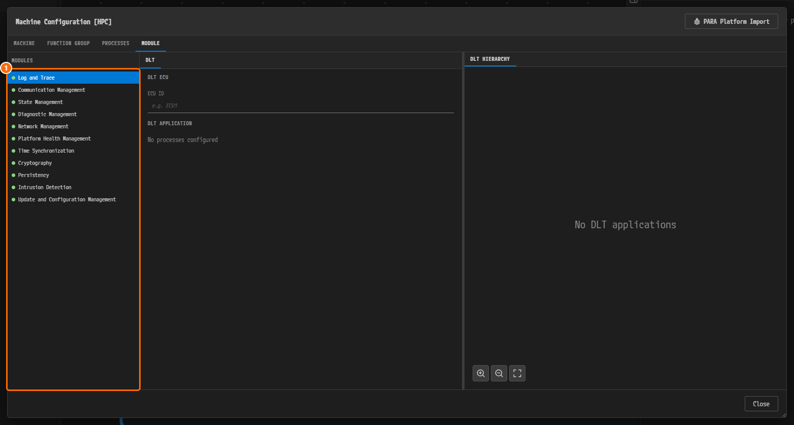
Figure 1-14. The MODULE tab. ① The MODULES list; the green dot in front of each module means that the module is enabled (tooltip
Enabled. Right-click to disable.). The center shows the DLT tab with the ECU ID field of the DLT ECU section (empty, hinte.g. ECU1) andNo processes configuredunder DLT APPLICATION. The DLT HIERARCHY tab on the right readsNo DLT applications.
The eleven modules in the list are, in order, Log and Trace, Communication Management, State Management, Diagnostic Management, Network Management, Platform Health Management, Time Synchronization, Cryptography, Persistency, Intrusion Detection, Update and Configuration Management. You change none of them in this chapter.
Saving and Closing
- Press
Ctrl+Sinside the dialog. Any tab will do. - Click the Close button at the bottom right.
- Click PROJECT › Save All.
Caution. Pressing Close alone does not create the machine file. The defaults filled in when the dialog opens leave no change record, so no save prompt appears either. Always press
Ctrl+Sinside the dialog. That is what createsdesign/Module/Machine/Ecu.machine.io.model.
Viewing the Validation Result
-
Look at the V icon in the footer at the bottom of the window, the fifth icon from the left. It already carries a red badge
1, and its tooltip readsValidation: 1 error(s), 0 warning(s), 0 info(s). -
Click the V icon to open the VALIDATION panel.

Figure 1-15. The VALIDATION panel. The header badge reads
1, the columns are ELEMENT TYPE / NAME / DESCRIPTION / CONSTR, and there is one row.
The one row of the panel is as follows.
| ELEMENT TYPE | NAME | DESCRIPTION | CONSTR |
|---|---|---|---|
StateManagementModuleInstantiation | SM | State-Management module "SM" of machine "Ecu" is missing maxActionListDuration. | constr_10641 |
The severity is error and there is exactly one finding. This result is expected. The State Management module that the dialog added by default has no value yet; it disappears when you fill in Max Action List Duration in Machine Configuration.
Why Is It Designed This Way?
- The node
Ecuand the compositionHPCare named separately. The machine file, the Ethernet endpoints and the DLT ECU path follow the node nameEcu, while the system mapping and the machine dialog title follow the composition nameHPC. If the two names were the same, later chapters could not tell which one they refer to. - The composition is created in the VFB first and mapped in the System editor. New Composition names the composition after the node, so it cannot follow the naming rule above.
- The machine dialog is opened and saved once even though no value changes. That writes the defaults, the function group
MachineFG, the processorCPUand the eleven modules, into the machine file, so the next chapters can fill in values on top of them.
Checklist
- The title bar reads
PAIO [AADesign], and System, VFB, Interface, DataType, Diagnostic are listed under DESIGN in the EDITOR view. - The System editor (tab
AADesign:System) holds one node,Ecu, whose header readsEcu [HPC], and the tab carries no modified mark. - The root canvas of the VFB editor (tab
AADesign:VFB) holds the compositionHPC [Ecu]with the machine icon at the right of its header. - NAME and AS PROTOTYPE in the property panel both read
HPC. - Clicking the machine icon opens the Machine Configuration [HPC] dialog; the FUNCTION GROUP tab holds
MachineFGand the MODULE tab holds eleven modules. -
design/in the project folder holds seven files:IVC.io.model,SYSTEM.io.model,VFB.io.model,Module/Machine/Ecu.machine.io.model,SWC/Composition/HPC.swc.io.model,SWC/Composition/System.swc.io.model,SWC/Layout/System.vfb.layout. - The VALIDATION panel shows exactly one finding,
constr_10641.
Next Step
In Machine Configuration you fill in the OS, the cores, the ECU ID of Log and Trace and the Max Action List Duration of State Management in the Machine Configuration dialog, which removes the one error left by this chapter.