Configuring the Machine
What You Will Do
In this chapter you fill real values into the machine Ecu that you saved with default values in Creating the Project and the HPC Machine.
On the MACHINE tab of the Machine Configuration dialog you set the OS to POSIX and grow the cores to four, Core0 through Core3.
On the FUNCTION GROUP tab you only check the states of the function group MachineFG, and on the MODULE tab you enter the ECU ID of Log and Trace and the Max Action List Duration of State Management.
When you finish this chapter, the machine file design/Module/Machine/Ecu.machine.io.model is updated, the validation error constr_10641 left over from chapter 1 disappears, and the VALIDATION panel shows No validation issues..
Before You Begin
- Start from the state at the end of Creating the Project and the HPC Machine. The title bar reads
PAIO [AADesign], the VFB root canvas holds the compositionHPC [Ecu], and the VALIDATION panel shows exactly one finding,constr_10641. - You may close the editor tabs left open from chapter 1. This chapter starts by opening VFB afresh from DESIGN in the EDITOR view.
You type only three values in this chapter. For the cores you only press a button three times; the names and IDs are filled in automatically.
| Tab | Item | Value |
|---|---|---|
| MACHINE | OS | POSIX |
| MACHINE | PROCESSOR | CPU (default, leave as is) |
| MACHINE | CORE table | + button three times → Core1 / 1, Core2 / 2, Core3 / 3 added automatically |
| FUNCTION GROUP | MachineFG | Do not change (check only) |
| MODULE › Log and Trace | ECU ID | ECU1 |
| MODULE › State Management › ACTION ITEMS | MAX ACTION LIST DURATION | 1000 (unit s) |
Note. An input field in the dialog commits its value only when you leave the field. In this chapter you press the
Tabkey after typing to commit. If OS breaks the AUTOSAR naming rule (a letter first, then only letters, digits and_), the value is not committed and the field reverts to its previous value.
Checking the Starting State
-
Look at the V icon in the footer at the bottom of the window, the fifth icon from the left. It already carries a red badge
1, and its tooltip readsValidation: 1 error(s), 0 warning(s), 0 info(s). -
If the VALIDATION panel is closed, click the V icon to open it.

Figure 2-1. The VALIDATION panel at the start of this chapter. The header badge is
1, and ① there is a single row,constr_10641.
The single row of the panel is as follows. The ELEMENT TYPE and DESCRIPTION columns are narrow and show only up to …Instantiati… and …missing maxAction… respectively, but the full texts are below.
| ELEMENT TYPE | NAME | DESCRIPTION | CONSTR |
|---|---|---|---|
StateManagementModuleInstantiation | SM | State-Management module "SM" of machine "Ecu" is missing maxActionListDuration. | constr_10641 |
The severity is error and there is exactly one finding. It means that the State Management module SM, which the machine dialog inserts by default, has no Max Action List Duration. The last input of this chapter resolves it.
Opening the Dialog
-
Click the V icon in the footer to close the VALIDATION panel. If the tab
AADesign:VFBis already open, click the × on the tab to close it. -
In the EDITOR view, click VFB under DESIGN. The tab
AADesign:VFBopens, and the root canvas (Systemat the top left) shows the compositionHPC [Ecu]. -
Click the blue three-bar machine icon at the right of the composition header.
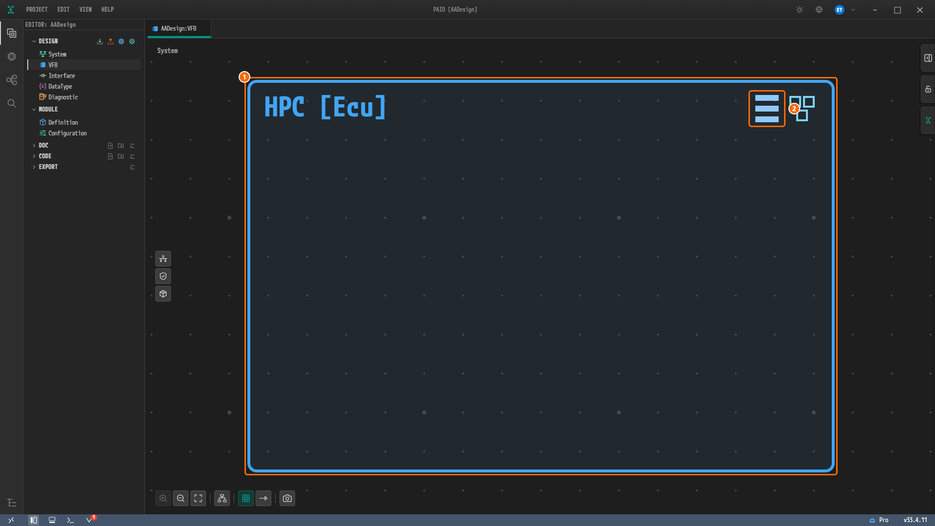
Figure 2-2. The VFB editor freshly opened from DESIGN in the EDITOR view. ① The composition
HPC [Ecu], ② the machine icon at the right of the header. The V icon in the footer shows the badge1. -
The dialog titled Machine Configuration [HPC] opens with the MACHINE tab selected. The name in brackets is the composition name, and the machine box on the center canvas is labeled
Ecu.
Note. In a VFB tab freshly opened from the EDITOR view, clicking the machine icon opens the dialog right away. There is no field for the machine name. The machine name and the machine file name follow the name of the HPC node
Ecuin the System editor as it is.
MACHINE Tab — OS and Cores
Entering POSIX as the OS
-
Click the OS field in the MACHINE panel on the right. It is empty and shows the hint
Name (letter, then A-Z/0-9/_)and the red messageName is required. -
Type
POSIXand press theTabkey. The red message disappears. -
Confirm that the PROCESSOR field in the PROCESSOR accordion reads
CPU. It is the default and you do not change it.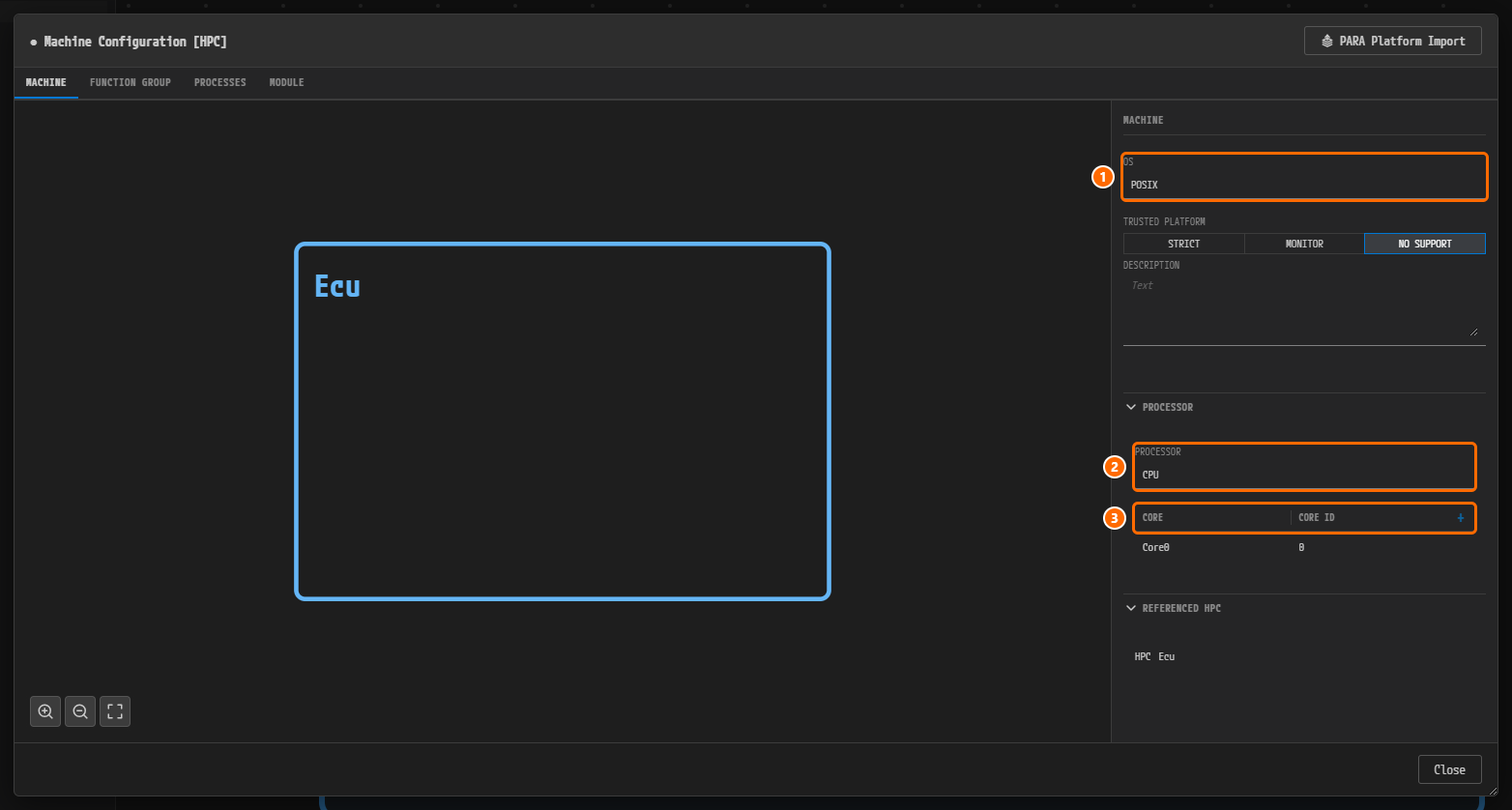
Figure 2-3. The MACHINE tab. ① OS =
POSIX, ② PROCESSOR =CPU, ③ the CORE / CORE ID table header with the + button at its right end. The table still has a single row,Core0/0. TRUSTED PLATFORM is NO SUPPORT, DESCRIPTION is empty, and REFERENCED HPC readsHPC Ecu.
Caution. When you press
Tabin the OS field, keyboard focus moves to the STRICT button of TRUSTED PLATFORM and an orange outline appears. The selection stays at NO SUPPORT. Do not press Space or Enter in that state; move on to the next step.
Adding Cores
-
Click the + button (tooltip
Add Core) at the right end of the CORE / CORE ID table header. -
The row
Core1/1is added to the table automatically. You do not need to type a name or an ID.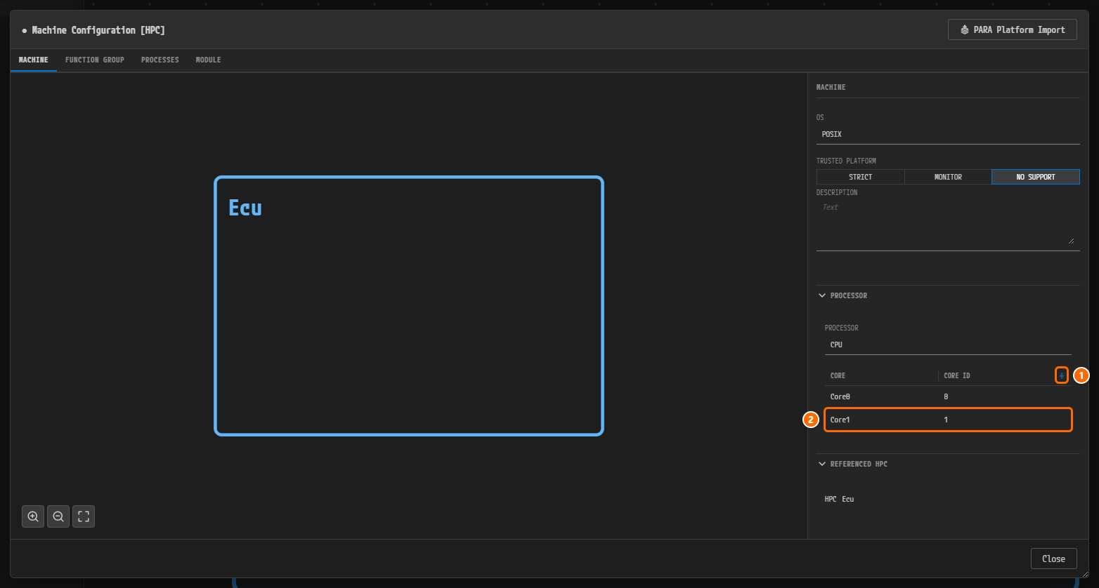
Figure 2-4. The CORE table after one press of the + button. ① The + button (
Add Core), ② the new rowCore1/1. -
Click the same + button two more times.
Core2/2andCore3/3are added in turn.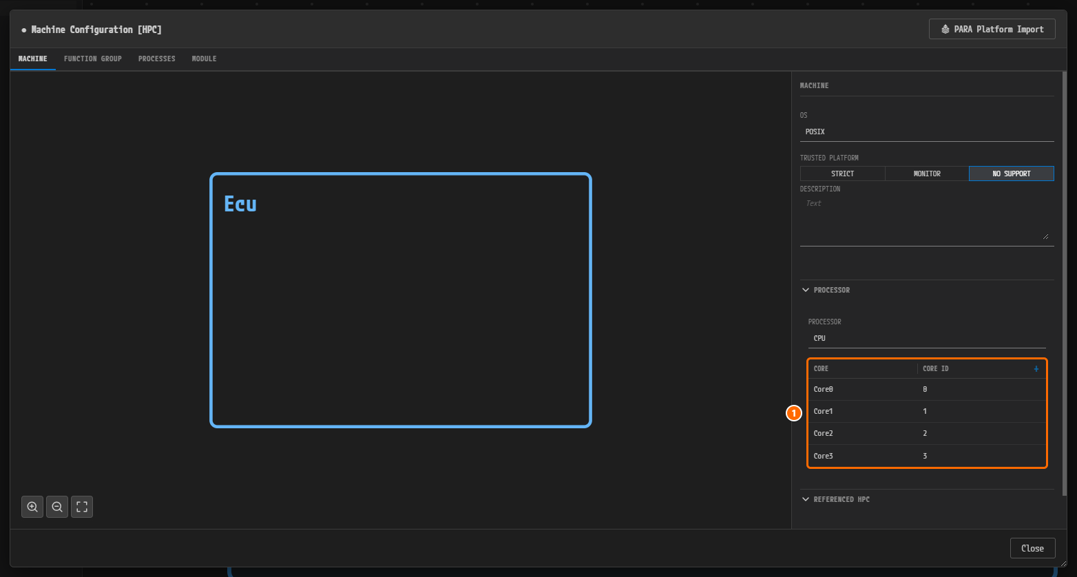
Figure 2-5. The CORE table with all four cores. ① The four rows
Core0/0,Core1/1,Core2/2,Core3/3. REFERENCED HPC is pushed below the table and only partly visible.
A new core is created with the name Core<N> and the ID N, where N is the largest existing core ID plus 1. You can click a cell to edit the name or the ID and remove a row with the × at its right, but this tutorial does not use either.
FUNCTION GROUP Tab — Checking MachineFG
You do not change anything on this tab. You only confirm that MachineFG, which later chapters use to bind processes to function group states, is still at its defaults.
-
Click the FUNCTION GROUP tab.
-
Confirm that the FUNCTION GROUPS list on the left holds a single entry,
MachineFG, and that it is selected.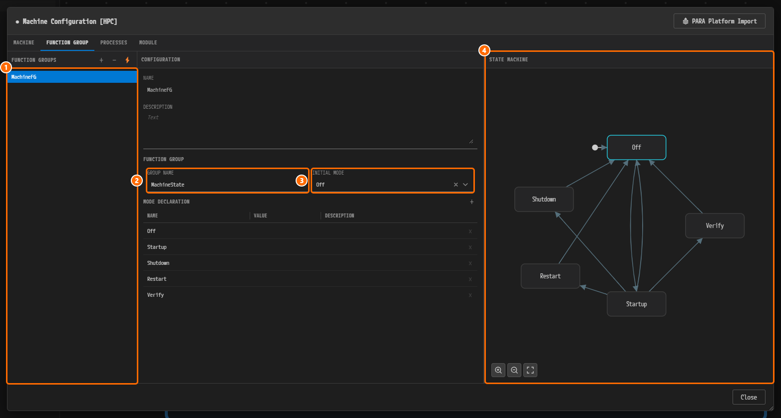
Figure 2-6. The FUNCTION GROUP tab. ①
MachineFGin the FUNCTION GROUPS list, ② GROUP NAME =MachineState, ③ INITIAL MODE =Off, ④ the STATE MACHINE diagram. The initial-state marker (a dot with an arrow) points atOff.
The values in the center CONFIGURATION panel are as follows.
| Item | Value |
|---|---|
| NAME | MachineFG |
| DESCRIPTION | empty |
| FUNCTION GROUP › GROUP NAME | MachineState |
| FUNCTION GROUP › INITIAL MODE | Off |
| MODE DECLARATION table (NAME / VALUE / DESCRIPTION) | five rows Off, Startup, Shutdown, Restart, Verify (VALUE and DESCRIPTION are all empty) |
The STATE MACHINE diagram on the right shows five state boxes (Off, Shutdown, Verify, Restart, Startup) and the transition arrows. There are eight transitions: Off→Startup, Startup→Shutdown, Startup→Restart, Startup→Verify, Startup→Off, Shutdown→Off, Restart→Off, Verify→Off.
MODULE Tab — ECU ID of Log and Trace
-
Click the MODULE tab. The first entry of the MODULES list on the left, Log and Trace, is selected, and the center shows a single sub-tab, DLT, with the sections DLT ECU and DLT APPLICATION below it.
-
Click the ECU ID field in the DLT ECU section. It is empty and shows the hint
e.g. ECU1. -
Type
ECU1and press theTabkey.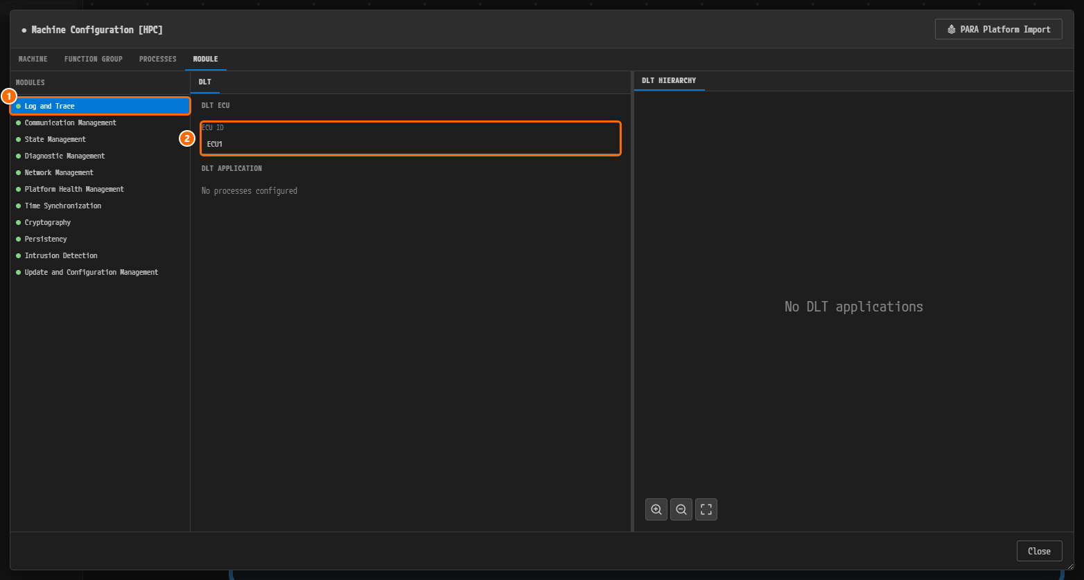
Figure 2-7. Log and Trace on the MODULE tab. ① Log and Trace in the MODULES list, ② ECU ID =
ECU1. DLT APPLICATION readsNo processes configuredand DLT HIERARCHY on the right readsNo DLT applications. There are no processes yet, so this is expected.
In the ARXML export this value becomes the ECU-ID of the DLT ECU element /DLT/Ecu/Ecu. The module itself is exported under the dialog's default name LOG.
MODULE Tab — Max Action List Duration of State Management
-
In the MODULES list, click State Management. The sub-tabs NOTIFICATIONS, REQUESTS and ACTION ITEMS sit at the top of the center panel, and NOTIFICATIONS is shown first.
-
Click the ACTION ITEMS sub-tab.
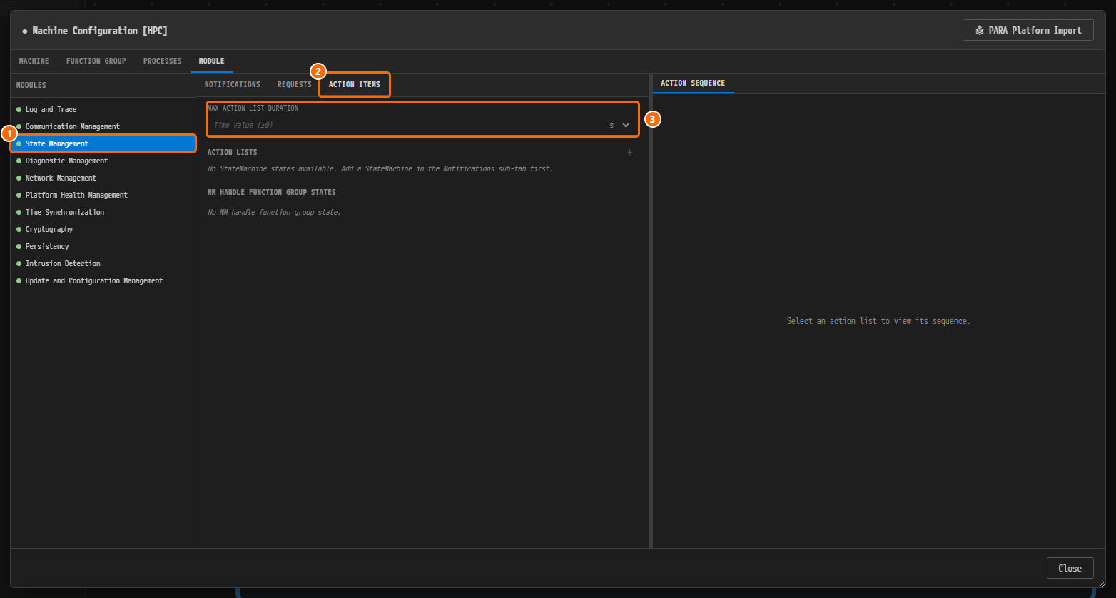
Figure 2-8. The ACTION ITEMS sub-tab of the State Management module. ① State Management in the MODULES list, ② the ACTION ITEMS sub-tab, ③ the empty MAX ACTION LIST DURATION field (hint
Time Value (≥0), unitson the right). Below, ACTION LISTS readsNo StateMachine states available. Add a StateMachine in the Notifications sub-tab first., NM HANDLE FUNCTION GROUP STATES readsNo NM handle function group state., and ACTION SEQUENCE on the right readsSelect an action list to view its sequence.. -
Type
1000into the MAX ACTION LIST DURATION field at the top and press theTabkey. Leave the unit on the right ats.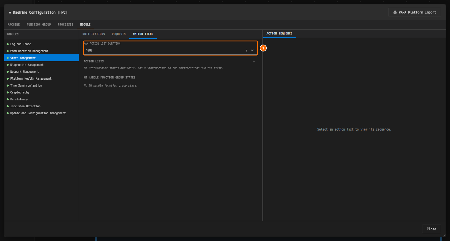
Figure 2-9. The ACTION ITEMS sub-tab after entering the value. ① MAX ACTION LIST DURATION =
1000, units. The other messages are unchanged.
ACTION LISTS, NM HANDLE FUNCTION GROUP STATES and ACTION SEQUENCE are not used in this tutorial, so leave them as they are. The unit choices are ns, us, ms and s; keep s.
Saving and Closing
- Press
Ctrl+Sinside the dialog. Any tab will do. The machine filedesign/Module/Machine/Ecu.machine.io.modelis updated. - Click the Close button at the bottom right.
- Click PROJECT › Save All.
Caution. Close alone does not save the machine file. Always press
Ctrl+Sinside the dialog before clicking Close. If a save prompt appears when you click Close, click Save.
Viewing the Validation Result
-
Look at the V icon in the footer. The red badge
1is gone. -
Look at the VALIDATION panel. If it is closed, click the V icon in the footer.

Figure 2-10. The VALIDATION panel after saving. The header has no badge and the body is a single line,
No validation issues..
constr_10641 is gone. Each later chapter, followed as designed, ends in this state too. Some of them show findings for a while as you edit, and those chapters say when.
Note. The badge on the V icon disappears when the count drops to zero, but the tooltip of the V icon keeps the last count,
Validation: 1 error(s), 0 warning(s), 0 info(s). The VALIDATION panel shows the current result.
Why Is It Designed This Way?
- The OS name is
POSIX. It becomes the name of theOS-MODULE-INSTANTIATIONin the exported ARXML. The value is stored as a property of the machine on the MACHINE tab; no OS module entry is added to the module list on the MODULE tab. - There are four cores,
Core0throughCore3, with IDs0through3. The + button assigns the names and IDs automatically, so you never have to line them up by hand. The processor name is the defaultCPU. ECU1is the identifier of the DLT ECU. In Logging and DLT, the DLT application of each Adaptive Application is gathered under this ECU.Max Action List Durationis a value that PAIO validation requires. Without it, the State Management moduleSMthat the dialog inserts by default raisesconstr_10641. The value is not used elsewhere in this design, so any sane value such as1000is fine.MachineFGis used at its defaults. In Executables and Processes, this function group appears as a candidate when you bind a process to a state ofMachineFGsuch asStartup. The export carriesEcu_FunctionGroup/MachineFGtogether with the eight transitions.- There is no field for the machine name. The machine name and the machine file name follow the name of the node
Ecuin the System editor. The MACHINE tab likewise has no field for admin data such asWAIT-FOR-SHUTDOWN, and the Communication Management module offers only the sub-tabs ACCESS CONTROL (three TRUE / FALSE switches, GRANTS and REMOTE SUBJECTS) and IPC, so timeout-style parameters cannot be entered. This chapter does not open that module.
Check Your Work
- On the MACHINE tab of the Machine Configuration [HPC] dialog, OS is
POSIXand the redName is requiredmessage is gone. - PROCESSOR is
CPU, and the CORE table has the four rowsCore0/0,Core1/1,Core2/2,Core3/3. - TRUSTED PLATFORM is NO SUPPORT and REFERENCED HPC reads
HPC Ecu. - The FUNCTION GROUP tab holds a single
MachineFGwith GROUP NAMEMachineState, INITIAL MODEOff, and the mode declarationsOff,Startup,Shutdown,Restart,Verify. - ECU ID under MODULE › Log and Trace is
ECU1. - MAX ACTION LIST DURATION under MODULE › State Management › ACTION ITEMS is
1000with units. - After PROJECT › Save All, no tab carries a modified marker.
- The VALIDATION panel shows
No validation issues.and the header has no badge.
Next Step
In Topology — Ethernet Connector and Endpoints you return to the System editor and create the Ethernet connector and the network endpoints on the node Ecu.