Logging and DLT
What You Will Do
In this chapter you double-click the five Adaptive Applications inside the composition HPC one after another to open the AA Internal Behavior dialog, and fill in the LOG CONFIG of the process card on the EXECUTION tab. For each process you set the APPLICATION ID, which is the DLT (Diagnostic Log and Trace) application ID, and the default log level DEFAULT LOG LEVEL. On Sensor, Fusion and Actuator you add one context each under DLT CONTEXTS. Sensor is shown as a procedure, Fusion and Actuator are repeated from a table, and CM and EM, which have no context, are shown with a single screen of CM. Finally you check in MODULE › Log and Trace of the Machine Configuration [HPC] dialog that the five applications are collected in the table.
When you finish this chapter, the process of the five *.swc.io.model files in design/SWC/AdaptiveApplication/ holds a filled-in log-config. In ARXML Export these become the reference design's five DLT-APPLICATION elements, three DLT-CONTEXT elements and five DLT-APPLICATION-TO-PROCESS-MAPPING elements.
Before You Begin
- Start from the state at the end of Service Instance Mapping. Each of the five Adaptive Applications has the one process created in Executables and Processes.
- The LOG CONFIG of the five processes is still at its defaults. The APPLICATION ID is empty, the DEFAULT LOG LEVEL is
INFO, the LOG MODE isCONSOLE, and DLT CONTEXTS is empty. - In Configuring the Machine you entered
ECU1as the ECU ID in MODULE › Log and Trace. The DLT applications of this chapter are collected under this DLT ECU. - The VALIDATION panel shows
No validation issues..
The only things you type on the keyboard in this chapter are five APPLICATION ID values (SENS, FUSN, ACTA, CM, EM) and three CONTEXT ID values (SENS, FUSN, ACTA). Everything else is a click, a toggle, the + button, Ctrl+S or Close.
| Adaptive Application (process) | APPLICATION ID | DEFAULT LOG LEVEL | LOG MODE | DLT CONTEXTS (CONTEXT ID) |
|---|---|---|---|---|
Sensor | SENS | VERBOSE | CONSOLE (left at default) | 1: SENS (LOG LEVEL left at default INFO) |
Fusion | FUSN | VERBOSE | CONSOLE | 1: FUSN |
Actuator | ACTA | VERBOSE | CONSOLE | 1: ACTA |
CM | CM | FATAL | CONSOLE | none |
EM | EM | FATAL | CONSOLE | none |
Leave APPLICATION DESCRIPTION and CONTEXT DESCRIPTION empty everywhere. The five Adaptive Applications are independent of each other, so any order works. This chapter does the three with contexts first and CM and EM afterwards.
Entering the LOG CONFIG and DLT Context of Sensor
Expanding LOG CONFIG
-
In the EDITOR view on the left, click VFB under DESIGN. The tab
AADesign:VFBopens with the composition nodeHPC [Ecu]on the root canvas. Double-click the nodeHPC [Ecu]. The breadcrumb changes toSystem > HPC, and the frameHPCshows the five nodes and two connectors created in chapter 8. If the tabAADesign:VFBfrom chapter 10 is still open and its breadcrumb already readsSystem > HPC, go straight to step 2.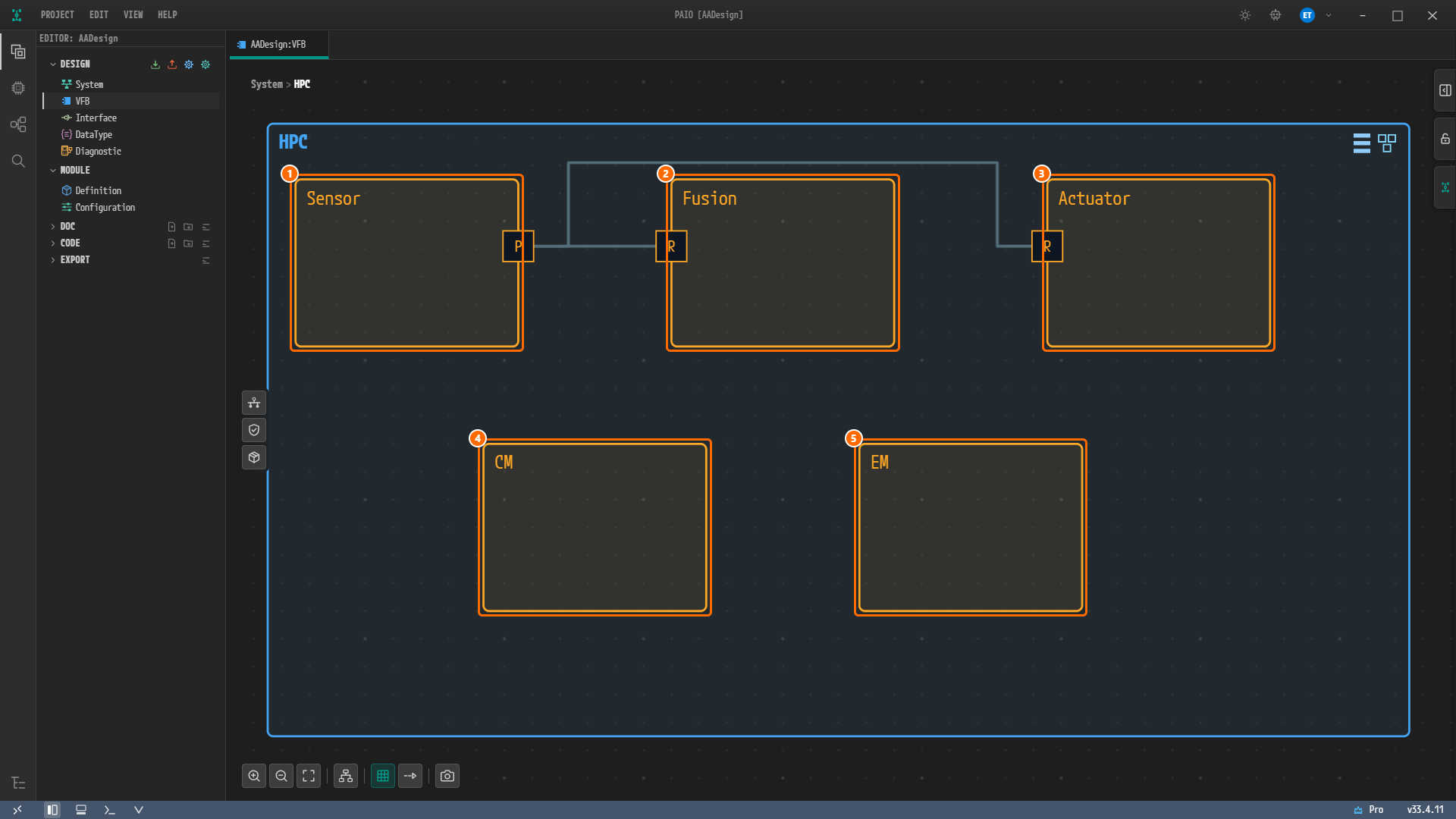
Figure 11-1. The VFB editor inside the composition
HPC. The numbers give the order in which this chapter configures them. ①Sensor, ②Fusion, ③Actuator, ④CM, ⑤EM. All five are opened in this chapter. The node arrangement may differ from the figure depending on the result of Auto Layout in chapter 8; it has no effect on the design values. -
Double-click the node
Sensor. The dialog AA Internal Behavior [Sensor] opens with the PROPERTIES tab selected. -
Click the EXECUTION tab in the panel on the right. The process card
Sensorcreated in chapter 9 appears. The accordions inside the card are, in order, STARTUP CONFIG, FUNCTION GROUP STATE, EXECUTION DEPENDENCY and LOG CONFIG. If the card is collapsed, click the card headerSensorto expand it. -
Click the collapsed LOG CONFIG header. It expands to show the fields APPLICATION ID and APPLICATION DESCRIPTION (both empty, with the hint text
String), the toggle DEFAULT LOG LEVEL (OFF,FATAL,ERROR,WARN,INFO,DEBUG,VERBOSE, defaultINFO) and the toggle LOG MODE (CONSOLE,FILE,NETWORK, defaultCONSOLE). At the very bottom is a collapsed DLT CONTEXTS.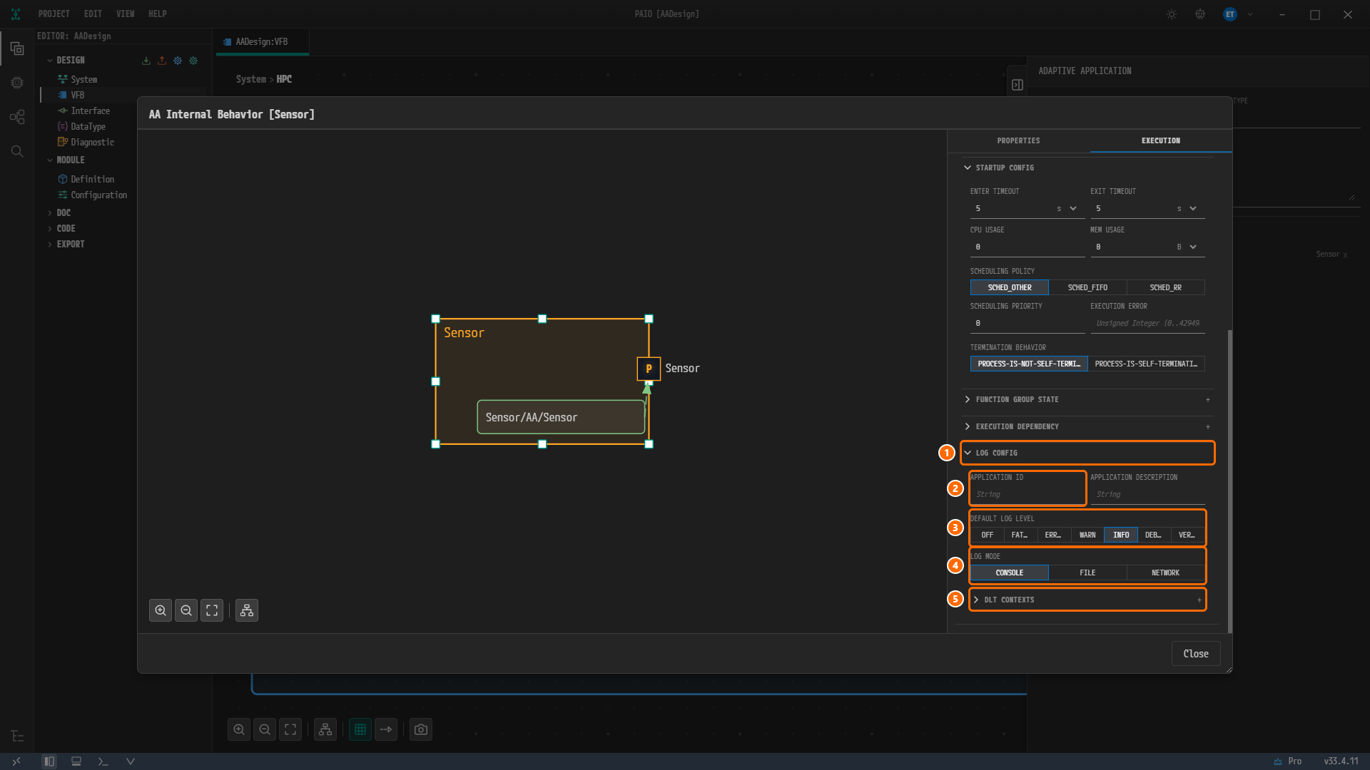
Figure 11-2. LOG CONFIG expanded on the EXECUTION tab. ① The LOG CONFIG header, ② the empty APPLICATION ID, ③ DEFAULT LOG LEVEL (
INFOis on), ④ LOG MODE (CONSOLEis on), ⑤ the collapsed DLT CONTEXTS. The STARTUP CONFIG above shows the timeout5entered in chapter 9.
Note. The DEFAULT LOG LEVEL buttons are narrow, so their labels may appear truncated. On screen they read
FAT…,ERR…,DEB…andVER…, which areFATAL,ERROR,DEBUGandVERBOSE. In the figures of this chapter the panel is scrolled down, so the card headerSensorhas moved out of view at the top.
Entering APPLICATION ID and DEFAULT LOG LEVEL
-
Type
SENSin the APPLICATION ID field and pressTab. The value is committed and the title gets the modified marker:● AA Internal Behavior [Sensor]. -
In DEFAULT LOG LEVEL, click
VERBOSE(shown asVER…).VERBOSEturns on. -
Leave LOG MODE at
CONSOLEand leave APPLICATION DESCRIPTION empty.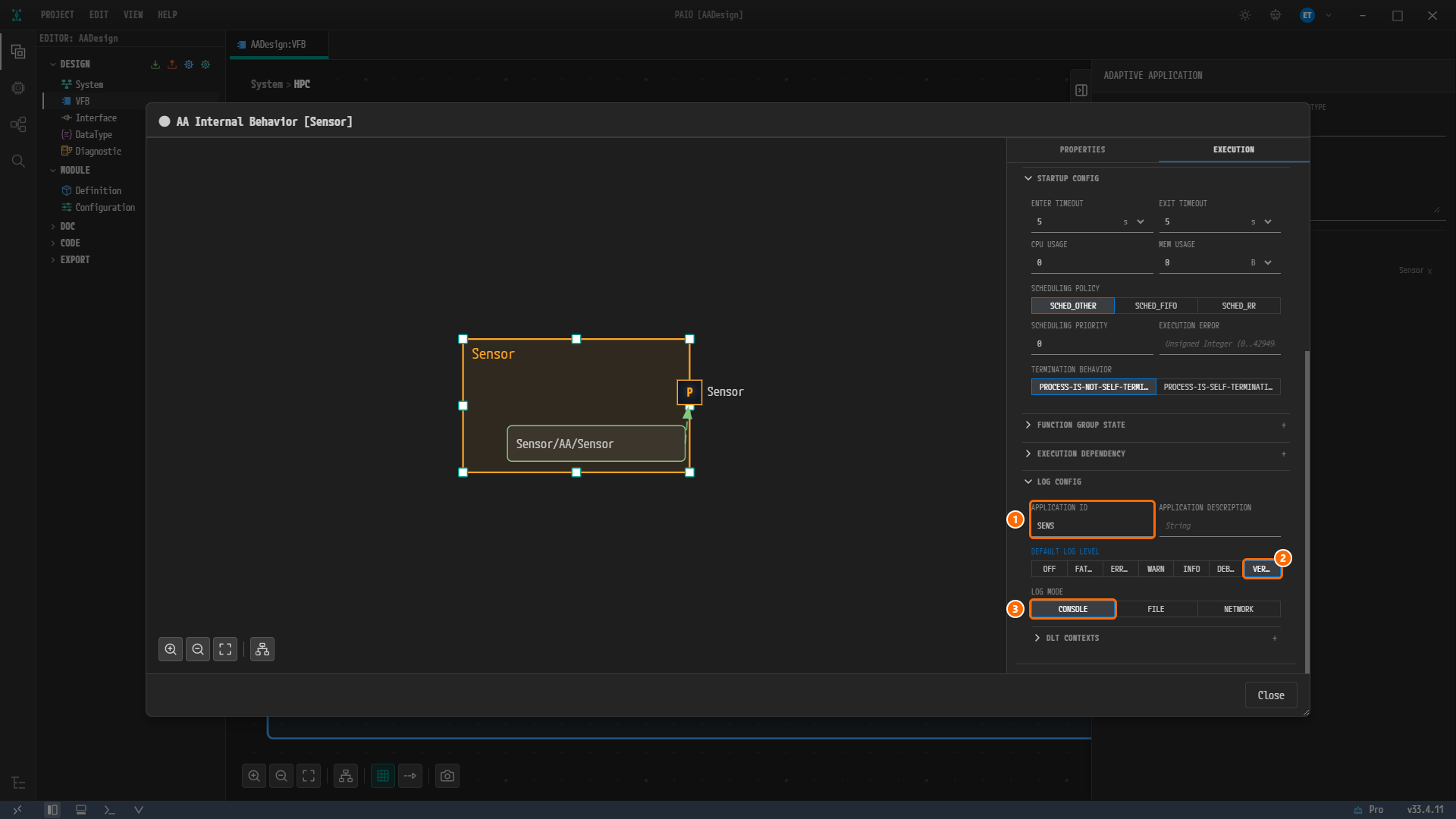
Figure 11-3. LOG CONFIG after entering the values. ① APPLICATION ID =
SENS, ② theVERBOSEbutton turned on, ③ theCONSOLEbutton left at its default. The title reads● AA Internal Behavior [Sensor].
Adding a DLT Context
-
Click the DLT CONTEXTS header inside LOG CONFIG to expand it. It reads
No DLT contexts defined. -
Click the + button (tooltip Add DLT Context) at the right of the DLT CONTEXTS header. One row
Context_0 : INFOappears, collapsed. The×at the end of the row, tooltip Remove DLT Context, deletes the row.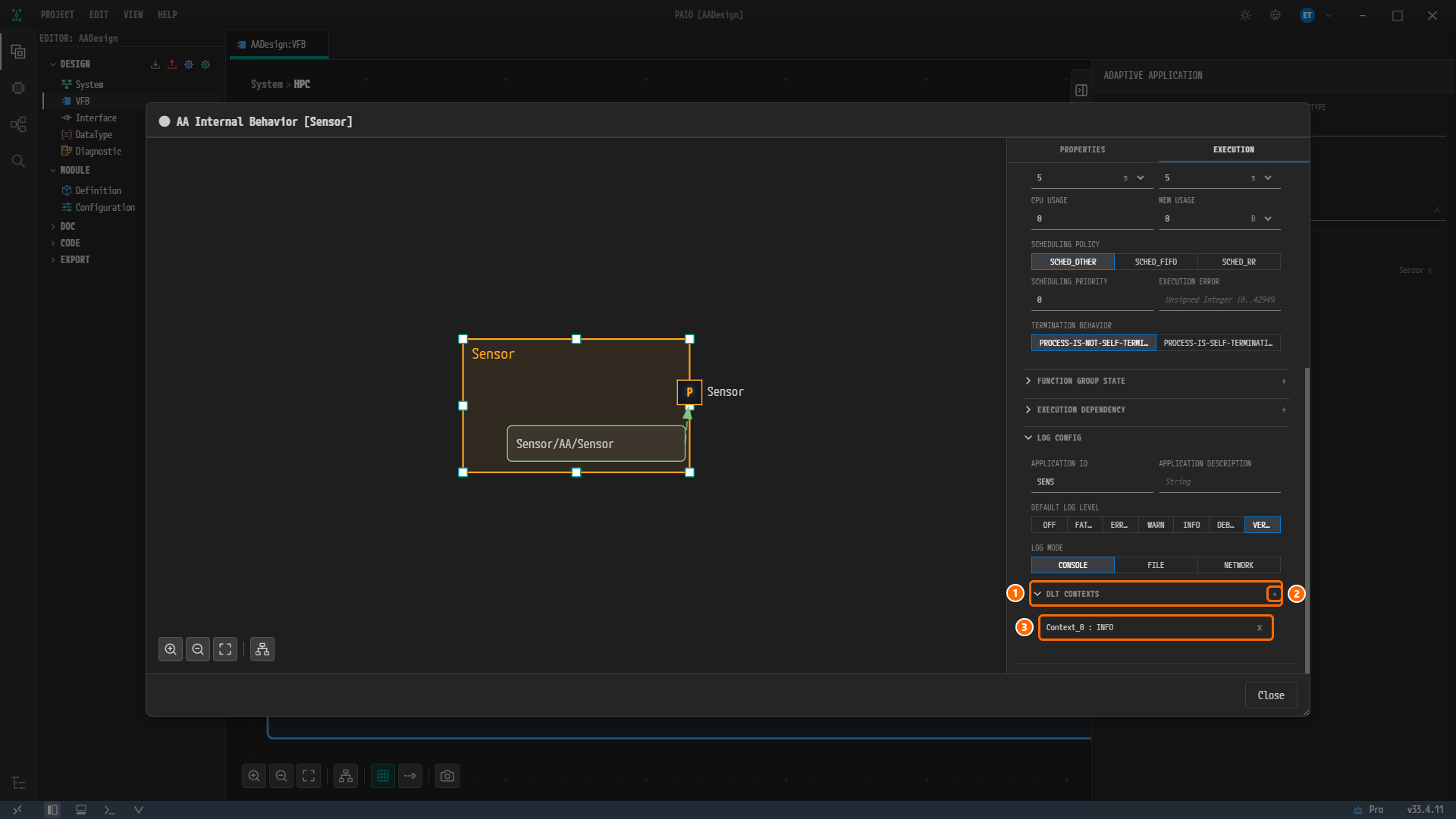
Figure 11-4. Just after adding a context. ① The DLT CONTEXTS header, ② the + button (Add DLT Context) at the right of the header, ③ the new row
Context_0 : INFO. The row header has the form<CONTEXT ID> : <LOG LEVEL>. -
Click the row header
Context_0 : INFOto expand it. You see CONTEXT ID (valueContext_0), CONTEXT DESCRIPTION (empty, with the hint textString) and the toggle LOG LEVEL (seven options fromOFFtoVERBOSE, defaultINFO). -
Delete
Context_0in the CONTEXT ID field, typeSENSand pressTab. The row header changes toSENS : INFO. -
Leave LOG LEVEL at
INFO.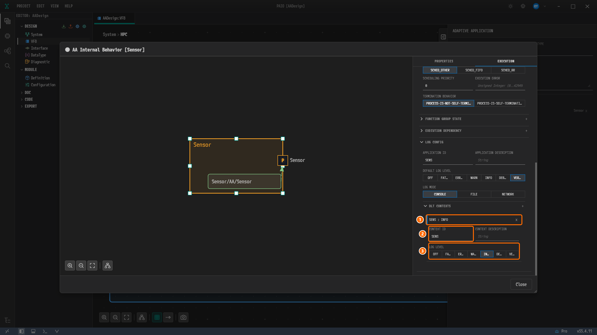
Figure 11-5. The expanded context row. ① The row header
SENS : INFO, ② CONTEXT ID =SENS, ③ LOG LEVEL (INFOis on). These buttons are even narrower and readFA…,IN…and so on. Above, APPLICATION IDSENS,VERBOSEandCONSOLEare unchanged.
Caution. A new context row is created collapsed. You have to click the row header once more before the CONTEXT ID field appears.
Note. The LOG LEVEL toggle has no empty option, so one value is always on. This chapter keeps the default
INFO. The difference from the reference design is described below under "Why Is It Designed This Way?".
Saving and Closing
-
Press
Ctrl+Sinside the dialog. The●disappears from the title, which becomesAA Internal Behavior [Sensor]. The EXECUTION tab stays selected and the values you entered remain visible.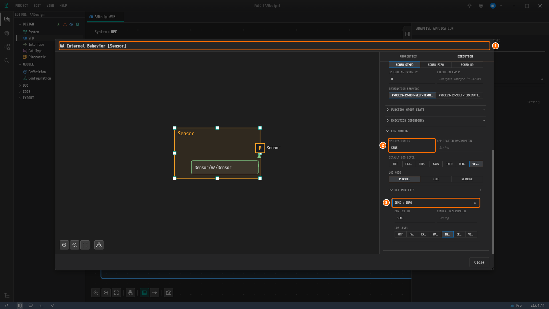
Figure 11-6. The screen after saving. ① The title
AA Internal Behavior [Sensor]without the modified marker, ② APPLICATION ID =SENS, ③ the rowSENS : INFO. -
Click Close. Because you saved, it closes without asking.
The following log-config is saved in the process of Sensor.swc.io.model. Ctrl+S inside the dialog also saves the AADesign:VFB tab, so after closing no tab carries the modified marker ●.
"log-config": {
  "application-id": "SENS",
  "default-log-level": "VERBOSE",
  "log-mode": "CONSOLE",
  "dlt-contexts": [
    { "context-id": "SENS", "log-level": "INFO" }
  ]
}
Entering Fusion and Actuator the Same Way
Enter Fusion and Actuator the same way. Double-click the node, expand LOG CONFIG on the EXECUTION tab, enter the values from the table, and add one context with the + button of DLT CONTEXTS. Expand the row, change the CONTEXT ID, and finish with Ctrl+S and Close.
| Node | APPLICATION ID | DEFAULT LOG LEVEL | CONTEXT ID | Row header after saving |
|---|---|---|---|---|
Fusion | FUSN | VERBOSE | FUSN | FUSN : INFO |
Actuator | ACTA | VERBOSE | ACTA | ACTA : INFO |
For both, leave LOG MODE at CONSOLE and LOG LEVEL at INFO. The log-config in Fusion.swc.io.model and Actuator.swc.io.model has the same shape as for Sensor; only application-id and context-id are FUSN and ACTA.
Entering CM and EM with FATAL and No Context
For CM and EM you enter only the APPLICATION ID and the DEFAULT LOG LEVEL and add no context.
-
Double-click the node
CM, click the EXECUTION tab, and expand LOG CONFIG. -
Type
CMin the APPLICATION ID field and pressTab. -
In DEFAULT LOG LEVEL, click
FATAL(shown asFAT…). Leave LOG MODE atCONSOLE. -
Expand DLT CONTEXTS to look. Leave it at
No DLT contexts definedand do not press the + button.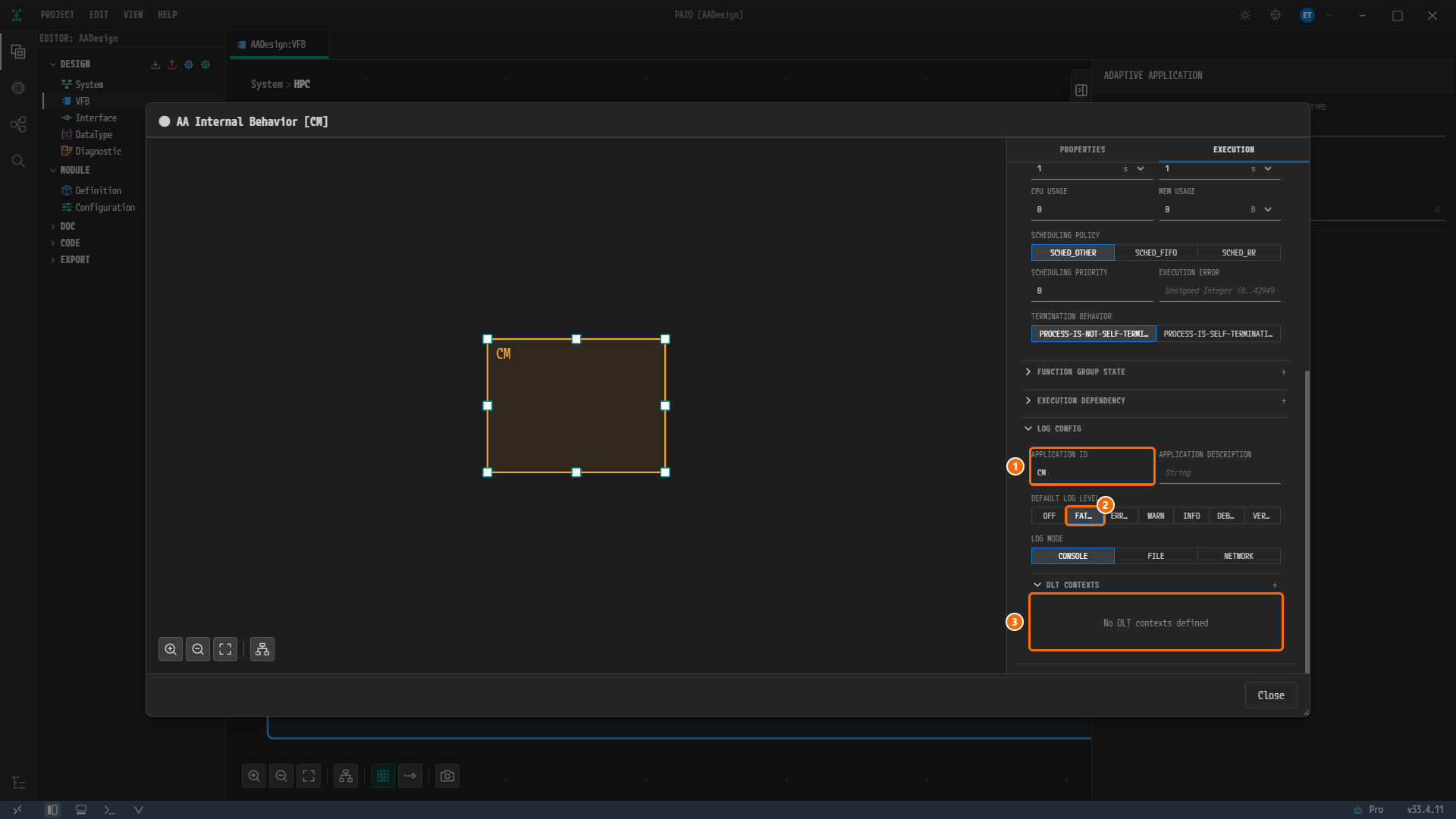
Figure 11-7. The
CMdialog before saving. ① APPLICATION ID =CM, ② theFATALbutton turned on, ③No DLT contexts defined. The title reads● AA Internal Behavior [CM], and the STARTUP CONFIG above shows the timeout1from chapter 9. -
Press
Ctrl+S, then click Close. It closes without asking.
Enter EM the same way.
| Node | APPLICATION ID | DEFAULT LOG LEVEL | DLT CONTEXTS |
|---|---|---|---|
EM | EM | FATAL | none |
The log-config in CM.swc.io.model is {"application-id":"CM","default-log-level":"FATAL","log-mode":"CONSOLE","dlt-contexts":[]}. For EM only the application-id is EM; the rest is the same.
Note. In DLT it is customary to keep application IDs and context IDs to four characters or fewer. All values in this chapter are four characters or fewer. Whether the product rejects longer values was not checked in this chapter. The five APPLICATION ID values must be distinct within the machine. What validation reports when IDs collide is shown in Validation.
Checking the Machine's Log and Trace Table
The log settings of the five processes are collected in the machine's Log and Trace module. You only check this table here; you do not edit it.
-
Click System in the breadcrumb of the VFB editor to return to the root canvas.
-
Click the machine icon at the right of the header of the composition
HPC [Ecu]. The dialog Machine Configuration [HPC] opens with the tabs MACHINE, FUNCTION GROUP, PROCESSES and MODULE. -
Click the MODULE tab, then click Log and Trace in the MODULES list on the left. The center shows a single sub-tab, DLT, with the sections DLT ECU and DLT APPLICATION below it.
-
Check the center. The ECU ID under DLT ECU is
ECU1, entered in chapter 2. Below it, the DLT APPLICATION table has the headers PROCESS, DLT APPLICATION ID, LOG MODE and DEFAULT LOG LEVEL, and five rows.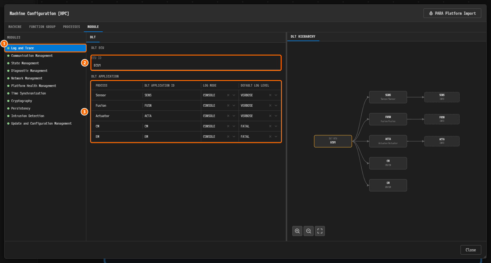
Figure 11-8. Log and Trace on the MODULE tab. ① Log and Trace in the MODULES list, ② ECU ID =
ECU1, ③ the five rows of the DLT APPLICATION table. In the DLT HIERARCHY on the right, theECU1box leads to the five applicationsSENS,FUSN,ACTA,CMandEM, and onlySENS,FUSNandACTAlead on to a context in a dashed box.PROCESS DLT APPLICATION ID LOG MODE DEFAULT LOG LEVEL SensorSENSCONSOLEVERBOSEFusionFUSNCONSOLEVERBOSEActuatorACTACONSOLEVERBOSECMCMCONSOLEFATALEMEMCONSOLEFATAL -
In the table, click the process-name side of the
Sensorrow. The row expands to show the badge SWC withSensor, and below itNo LogAndTrace ports.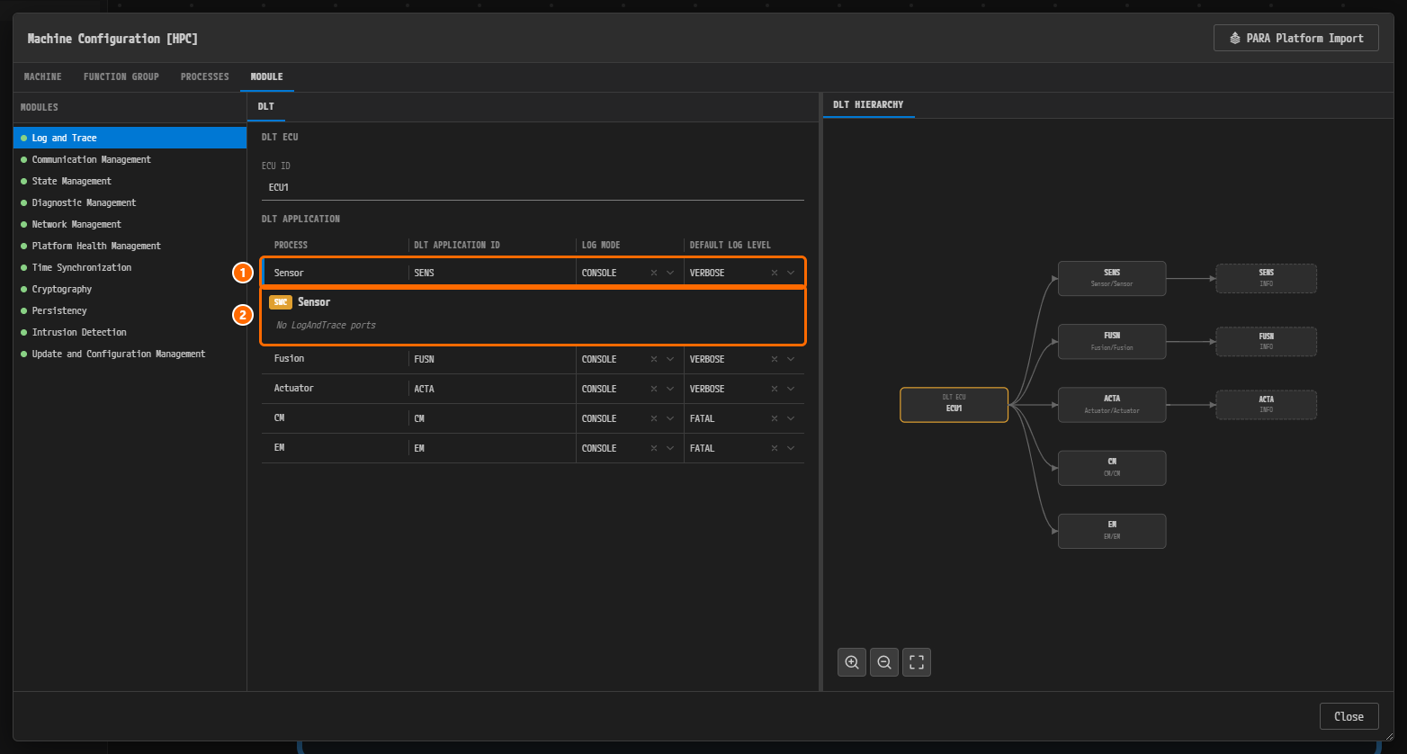
Figure 11-9. The expanded
Sensorrow. ① TheSensorrow, ② the expanded content SWCSensorandNo LogAndTrace ports. This design has no logging ports, so this message is expected. -
Click Close to close the dialog.
Note. When you looked at the same place in chapter 2, DLT APPLICATION read
No processes configuredand DLT HIERARCHY readNo DLT applications. The five rows are the result of creating the processes in chapter 9 and filling in LOG CONFIG in this chapter. The name in the brackets of the machine dialog title is the composition nameHPC, not the machine nameEcu.
Note. In the table, the DLT APPLICATION ID cell is an input field, and the LOG MODE and DEFAULT LOG LEVEL cells are dropdowns with
×and⌄. This chapter enters values only in the AA dialog. Whether a value changed in this table is carried back to the LOG CONFIG of the Adaptive Application was not checked.
Viewing the Validation Result
-
Look at the V icon in the footer at the bottom of the window, the fifth icon from the left. It carries no badge.
-
Look at the VALIDATION panel. If it is closed, click the V icon in the footer. The header carries no badge, and under the column headers ELEMENT TYPE, NAME, DESCRIPTION and CONSTR the body reads
No validation issues..
Figure 11-10. The VALIDATION panel after saving all five dialogs. The body reads
No validation issues..
Why Is It Designed This Way?
- There are five DLT applications and three contexts. The reference design has five
DLT-APPLICATIONelements,SENS,FUSN,ACTA(VERBOSE,CONSOLE) andCM,EM(FATAL,CONSOLE), and only threeDLT-CONTEXTelements,SENS,FUSNandACTA. Each context ID equals its application ID. The input of this chapter copies these values as they are.VERBOSEemits logs of every level, andFATALemits only fatal errors. - The APPLICATION ID becomes the name in the export. In the export the APPLICATION ID becomes both the
SHORT-NAMEand theAPPLICATION-IDof theDLT-APPLICATION(/DLT/Ecu/Ecu/SENSand so on). The DLT ECU path/DLT/Ecu/Ecuis also the same as in the reference design. The five links to the processes, fromMapping_SENS_TO_SensortoMapping_EM_TO_EM, come out with the same names as in the reference design. - The context name becomes
DltContext_0. The contextSHORT-NAMEin the reference design isSENS, but PAIO has no field for the contextSHORT-NAME, so the export names itDltContext_0. The CONTEXT ID valueSENSis kept. - The context LOG LEVEL may differ from the reference design. The
DLT-CONTEXTelements of the reference design have an empty log level. Because one value of the PAIO LOG LEVEL toggle is always on, an export built by following this chapter may carryINFO. An export built along this path was not measured. - There are no logging ports. The reference design has neither a
DLT-LOG-SINKnor an ara::log port. That is whyNo LogAndTrace portsin Figure 11-9 is expected. - The log settings of
EMare the same as in the reference design. BindingEMto theStartupstate ofMachineFGis a deliberate deviation from the reference design, but that difference belongs to Executables and Processes and has nothing to do with the LOG CONFIG of this chapter.
Checklist
- In the LOG CONFIG of
Sensor,FusionandActuator, the APPLICATION ID isSENS,FUSNandACTArespectively, the DEFAULT LOG LEVEL isVERBOSEand the LOG MODE isCONSOLE. - DLT CONTEXTS of these three has one row each, with the headers
SENS : INFO,FUSN : INFOandACTA : INFO. - The APPLICATION ID of
CMandEMisCMandEM, the DEFAULT LOG LEVEL isFATAL, and DLT CONTEXTS readsNo DLT contexts defined. - Neither the dialog title nor the tab
AADesign:VFBcarries a modified marker●. - The DLT APPLICATION table in Machine Configuration [HPC] › MODULE › Log and Trace has five rows, and in the DLT HIERARCHY
ECU1leads to the five applications. - The VALIDATION panel shows
No validation issues.and the header carries no badge.
Next Step
In Validation you validate the design built so far and see how deliberately planted defects are reported in the VALIDATION panel.