The Service Interface
What You Will Do
In this chapter you create one service interface in the project AADesign that you finished in Data Types.
In the SERVICE tab of the Interface editor, you use the + button to add the interface Sensor (C++ namespace sensor::service, version 1 / 0), add the event SensorData (type ByteArray) and the method Calculation (REQUEST AND RESPONSE, IN arguments front, rear, left, right and OUT argument result, all of type float32), and save.
When you finish this chapter, a new file design/INTERFACE.io.model exists and holds the single service interface Sensor. The VALIDATION panel shows No validation issues. throughout this chapter. In the later chapters, SOME/IP Deployment and Service Instances attaches a SOME/IP deployment to this interface, and Adaptive Applications and Ports uses this interface on the ports of three AAs.
Before You Begin
- Start from the state at the end of Data Types. The title bar reads
PAIO [AADesign], the project'sdesign/folder holdsDATATYPE.io.model(ByteArray,String),IVC.io.model,SYSTEM.io.model,VFB.io.modelplusModule/andSWC/, and neitherINTERFACE.io.modelnorSERVICE.io.modelexists yet. The VALIDATION panel showsNo validation issues.. - You may close the tab
AADesign:DataTypeleft open from chapter 4. This chapter starts by opening Interface from DESIGN in the EDITOR view.
The values you type or pick in this chapter are listed below. DESCRIPTION stays empty everywhere, and MAJOR VERSION / MINOR VERSION and METHOD TYPE keep their defaults.
| Element | NAME | Other values |
|---|---|---|
| Service interface | Sensor | C++ NAMESPACE sensor::service, MAJOR VERSION 1, MINOR VERSION 0 (defaults) |
| Event | SensorData | Select ByteArray from the TYPE dropdown |
| Method | Calculation | METHOD TYPE REQUEST AND RESPONSE (default) |
The five arguments of the method Calculation are created in this order.
| # | DIRECTION | TYPE | NAME |
|---|---|---|---|
| 1 | IN (default) | float32 | front |
| 2 | IN (default) | float32 | rear |
| 3 | IN (default) | float32 | left |
| 4 | IN (default) | float32 | right |
| 5 | OUT (select from the dropdown) | float32 | result |
Note. A NAME field commits its value when you press the
Enterkey or leave the field. In this chapter you press theEnterkey after typing a name, and theTabkey after typing the C++ NAMESPACE. A choice in a dropdown or in the METHOD TYPE segment commits as soon as you click it.
Opening the Interface Editor
Opening the Editor and Checking the SERVICE Tab
-
In the EDITOR view on the left, click Interface under DESIGN. The tab
AADesign:Interfaceopens. -
Look at the seven category tabs at the top of the editor: SERVICE, SENDER-RECEIVER, CLIENT-SERVER, MODE-SWITCH, ADAPTIVE, ERROR DOMAIN and MAPPING. The SERVICE tab is active as soon as the editor opens. This chapter uses only the SERVICE tab.
-
Look at the three panels. The INTERFACES list on the left is empty and shows
Add an interface, the CONFIGURATION panel in the middle showsSelect an interface, and the SOA DEPLOYMENT subtab on the right showsSelect a service interface.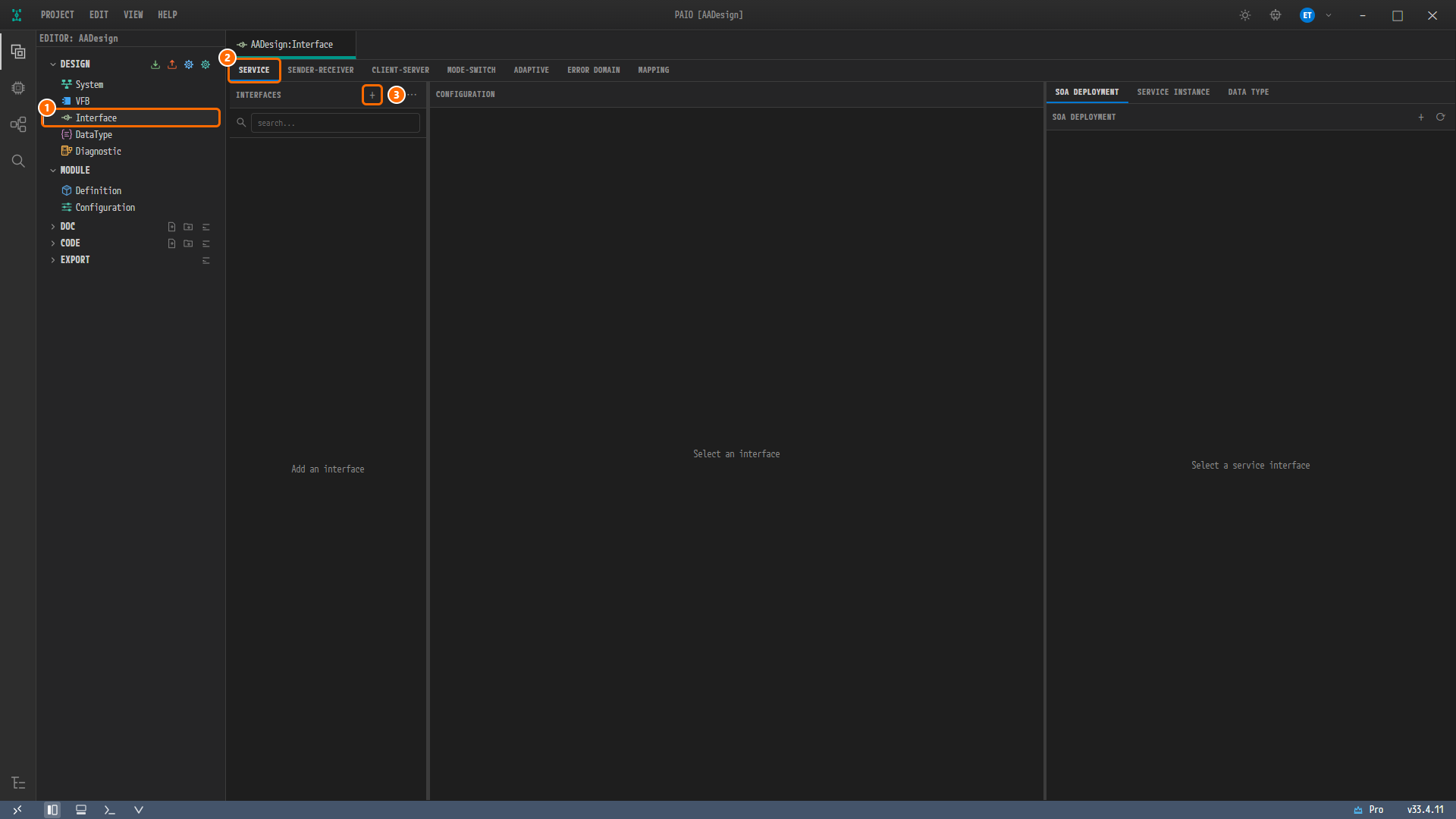
Figure 5-1. The Interface editor as first opened. ① The Interface row under DESIGN in the EDITOR view, ② the active SERVICE category tab, ③ the + button in the INTERFACES header (tooltip
Add Interface). The panel on the right has the subtabs SOA DEPLOYMENT, SERVICE INSTANCE and DATA TYPE, and SOA DEPLOYMENT is active.
The INTERFACES header on the left has the buttons + (Add Interface), − and ⋯, and a search field (hint search...). This chapter uses only the + button and the CONFIGURATION panel. The other six category tabs, −, ⋯, the search field and the SERVICE INSTANCE subtab on the right are not used.
Note. The Interface file of the reference design holds exactly one element, the service interface
Sensor. The other six tabs such as SENDER-RECEIVER stay empty for the whole tutorial.
Creating the Service Interface Sensor
Adding the Interface
-
Click the + button in the INTERFACES header. A new entry
ServiceInterface_0appears in the list and is selected immediately. -
Look at the CONFIGURATION panel. NAME is
ServiceInterface_0, C++ NAMESPACE is empty (hintC++ Namespace (e.g., paio::api)), MAJOR VERSION is1, MINOR VERSION is0, and DESCRIPTION is empty (hintText). Below them are the subtabs EVENTS, METHODS and FIELDS with a + button at the right end of the row; EVENTS is active, soAdd an eventis shown.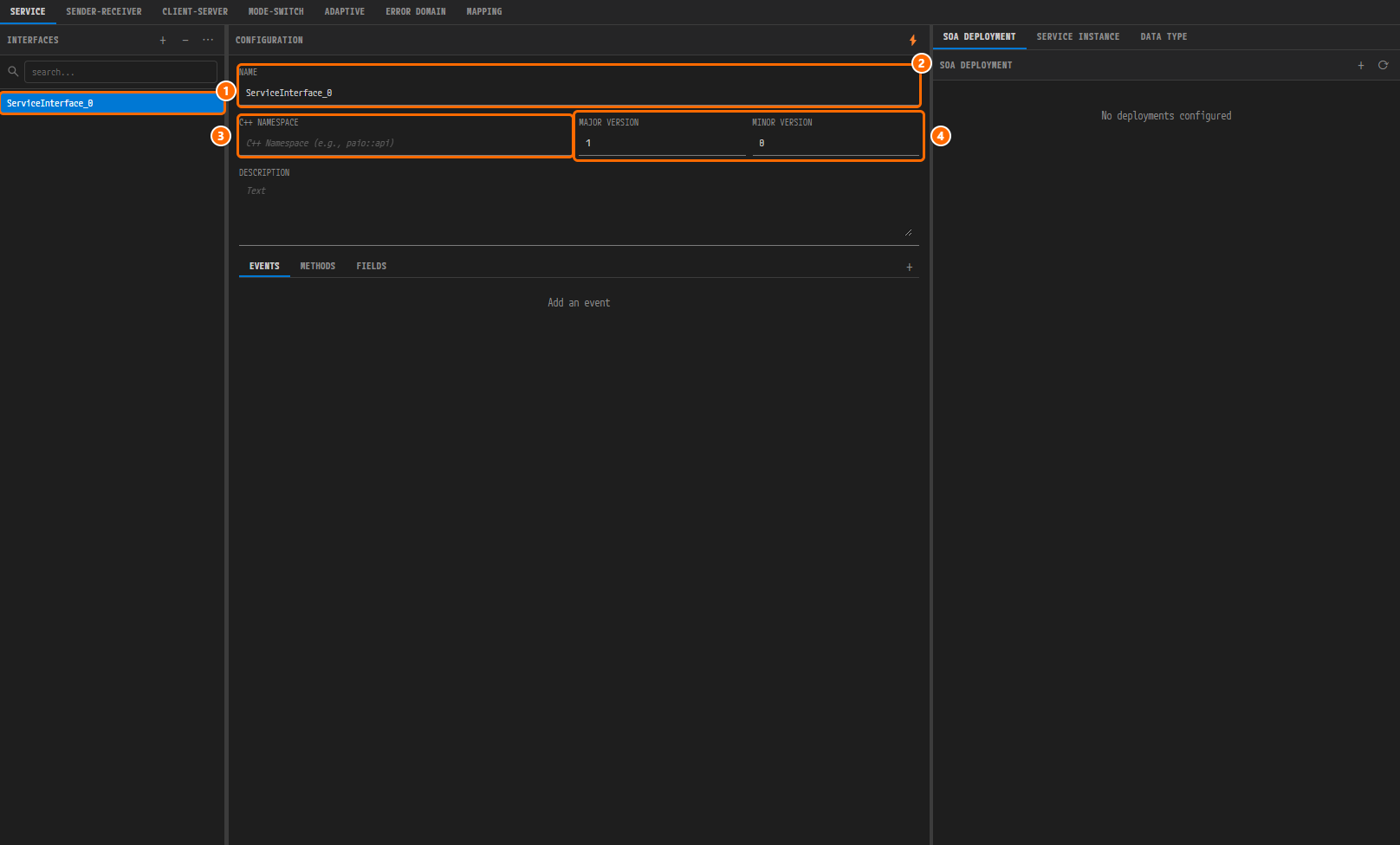
Figure 5-2. The editor right after adding the interface. ① The
ServiceInterface_0row in the list, ② NAME =ServiceInterface_0, ③ the empty C++ NAMESPACE field, ④ MAJOR VERSION =1and MINOR VERSION =0. The SOA DEPLOYMENT panel on the right changes toNo deployments configured, and the tabAADesign:Interface, outside the figure, carries the modified mark ●.
The name of a new interface is assigned automatically, such as ServiceInterface_0. The No deployments configured in the SOA DEPLOYMENT panel on the right is filled in SOME/IP Deployment and Service Instances.
Entering the Name and the Namespace
-
Change the value of the NAME field to
Sensorand press theEnterkey. The row in the list changes toSensoras well. -
Type
sensor::serviceinto the C++ NAMESPACE field and press theTabkey. -
Leave MAJOR VERSION
1and MINOR VERSION0as they are. They are the same values as in the reference design.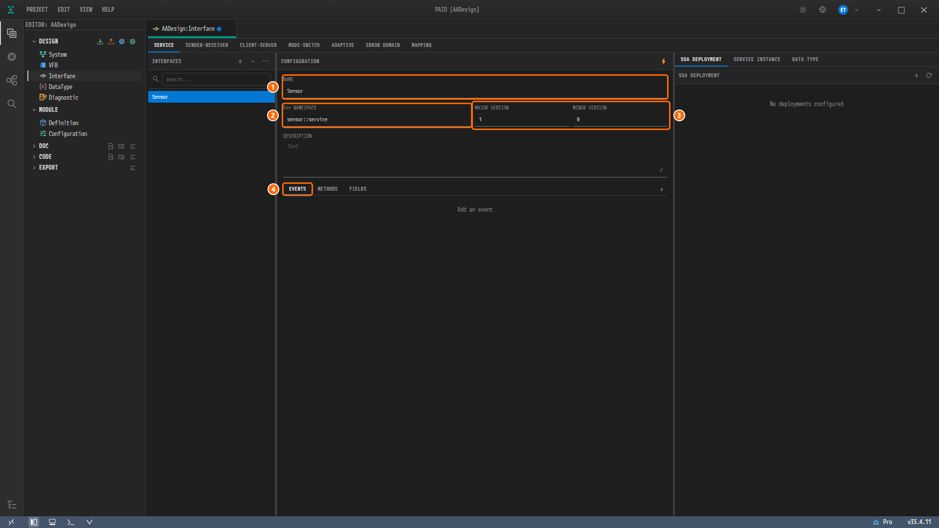
Figure 5-3. The interface
Sensorwith its basic information entered. ① NAME =Sensor, ② C++ NAMESPACE =sensor::service, ③ MAJOR VERSION =1and MINOR VERSION =0, ④ the active EVENTS subtab. The row in the list readsSensorand DESCRIPTION is empty.
Adding the Event SensorData
Adding the Event and Entering Its Name
- Make sure the EVENTS subtab is active. Click the + button at the right end of the subtab row (tooltip
Add Event). A new rowEvent_0appears under the column headers NAME, TYPE and DESCRIPTION, its TYPE isuint8, and the row is expanded so that the detail fields NAME, TYPE and DESCRIPTION are shown below it. - Change the value of the NAME field in the detail to
SensorDataand press theEnterkey. The row header changes toSensorDataas well.
The name of a new event is assigned automatically, such as Event_0, and its type is set to uint8. Clicking the row header collapses the detail, and clicking it again expands it.
Picking the Type ByteArray
-
Click the ⌄ at the right end of the TYPE field in the detail. A search field (hint
Type to search...) and a dropdown open. The dropdown holds 13 entries in this order: the 11 primitivesboolean,float32,float64,sint8,sint16,sint32,sint64,uint8,uint16,uint32,uint64, thenByteArrayandStringcreated in chapter 4, and the current valueuint8carries a ✓. About six rows are visible at a time, so scroll to findByteArray. -
Click
ByteArrayin the dropdown.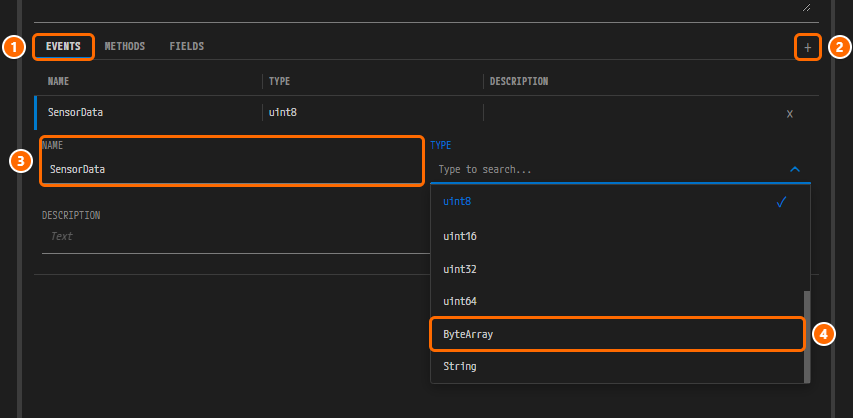
Figure 5-4. The EVENTS table with the TYPE dropdown open. ① The active EVENTS subtab, ② the + button at the right end of the row (tooltip
Add Event), ③ the NAME field in the detail =SensorData, ④ theByteArrayrow to click in the dropdown. The dropdown shows the rowsuint8✓,uint16,uint32,uint64,ByteArrayandString, with a scrollbar on the right. -
Check that the row header now reads
SensorDataByteArray. The panel on the right switches to the DATA TYPE subtab by itself and shows the content of the chosen typeByteArray.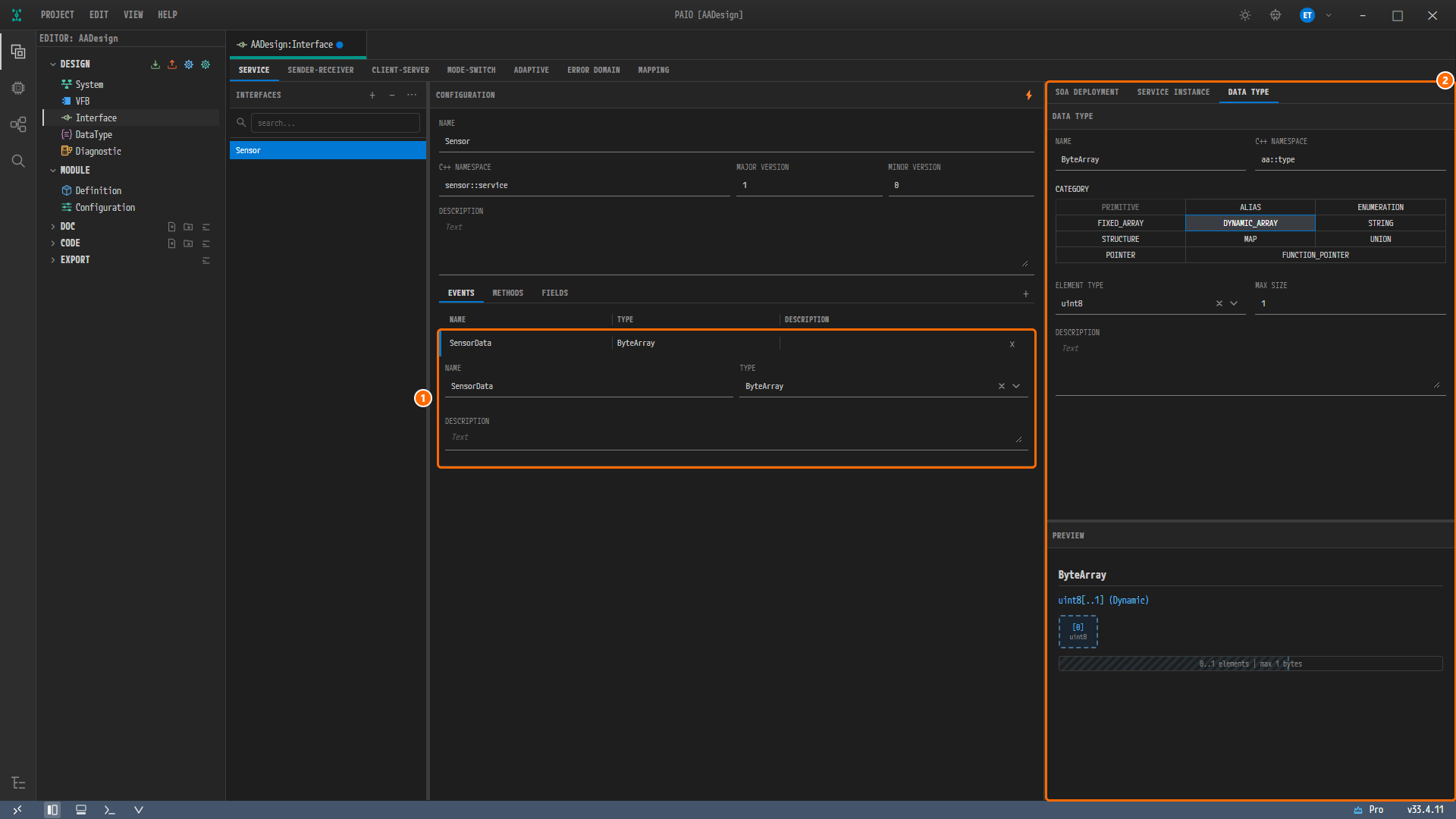
Figure 5-5. The editor with the event
SensorDatacompleted. ① TheSensorDataByteArrayrow of the EVENTS table and its detail (NAME =SensorData, TYPE =ByteArray), ② the DATA TYPE panel on the right. The panel shows NAMEByteArray, C++ NAMESPACEaa::type, DYNAMIC_ARRAY selected in CATEGORY, ELEMENT TYPEuint8and MAX SIZE1, and PREVIEW below showsByteArray,uint8[..1] (Dynamic),[0] uint8and0..1 elements | max 1 bytes.
Note. Whenever you pick the type of an event or an argument, the panel on the right switches to the DATA TYPE subtab, an embedded DataType editor that shows the chosen type. A built-in primitive such as
float32is read-only there, but a type of this project such asByteArraycan be edited there: the change applies to the type itself, puts the modified mark ● on the tabAADesign:Interface, and is saved when you pressCtrl+Sin that tab. Change nothing there in this chapter. To return to SOA DEPLOYMENT, click that subtab again. The dropdown lists only the types that exist in the DataType editor, which is whyByteArraywas created first in Data Types.
Adding the Method Calculation
Adding the Method
-
Click the METHODS subtab. The table is empty and shows
Add a method. -
Click the + button at the right end of the subtab row (tooltip
Add Method). A new rowMethod_0appears under the column headers NAME, ARGS, ACCESS and DESCRIPTION, its ARGS is() → ErrorCode, its ACCESS is the badgeR&R, and the row is expanded to show its detail. -
Change the value of the NAME field in the detail to
Calculationand press theEnterkey. The row header changes toCalculationas well. -
Leave the METHOD TYPE segment with REQUEST AND RESPONSE selected.
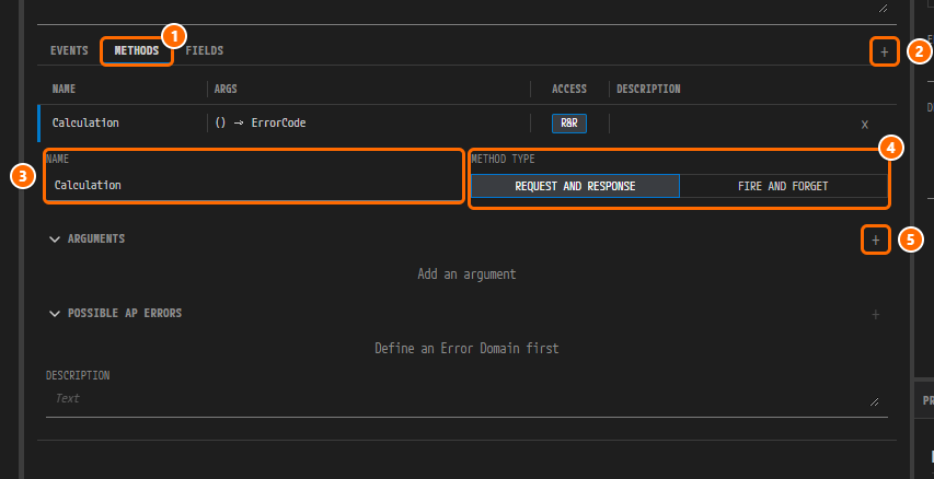
Figure 5-6. The METHODS table right after adding the method
Calculation. ① The active METHODS subtab, ② the + button at the right end of the row (tooltipAdd Method), ③ the NAME field in the detail =Calculation, ④ the METHOD TYPE segment (REQUEST AND RESPONSE selected, FIRE AND FORGET on the right), ⑤ the + button of the ARGUMENTS accordion (tooltipAdd Argument). The row header readsCalculation() → ErrorCodeR&R, ARGUMENTS showsAdd an argument, and POSSIBLE AP ERRORS showsDefine an Error Domain first.
Below NAME and METHOD TYPE, the detail has the accordions ARGUMENTS and POSSIBLE AP ERRORS, followed by DESCRIPTION. The ACCESS badge R&R stands for REQUEST AND RESPONSE and its tooltip is Request and Response. POSSIBLE AP ERRORS can only be used once an Error Domain exists and is not used in this chapter.
Adding the First Argument front
The first of the five arguments, front, is shown step by step. The order is: enter the name, then pick the type; DIRECTION keeps its default IN.
- Click the + button at the right end of the ARGUMENTS accordion (tooltip
Add Argument). A new row1appears under the column headers #, DIRECTION, TYPE, NAME and DESCRIPTION. Its DIRECTION isIN, its TYPE isuint8, and its NAME isargument_0. - Change the value of the row's NAME cell to
frontand press theEnterkey. - Click the ⌄ at the right end of the row's TYPE cell. The same dropdown of 13 entries as for the event opens. Click
float32. The DATA TYPE panel on the right changes tofloat32. - Check that the row now reads
1INfloat32front.
Adding the Remaining Arguments
In the same way, add rear, left, right and result as listed in the table under "Before You Begin". Each click on the + button adds a new row argument_0 (IN, uint8) at the bottom of the table, so for each row type the NAME, press the Enter key, and pick float32 in TYPE. Only the fifth row, result, changes its DIRECTION.
-
Add rows 2 to 4,
rear,leftandright. DIRECTION staysIN. -
Click the + button once more to create row 5.
-
Click the ⌄ at the right end of the DIRECTION cell of row 5. The cell turns into a search field (hint
Type) and the dropdown showsIN✓,OUTandINOUT. -
Click
OUTin the dropdown.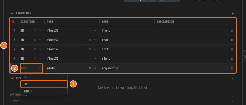
Figure 5-7. The ARGUMENTS table with the DIRECTION dropdown open. ① Rows 1 to 4,
INfloat32front,rear,left,right, and row 5, ② the DIRECTION cell of row 5 (in search state, so the hintTypeis shown), ③ theOUTrow to click in the dropdown. The TYPE and NAME of row 5 are stilluint8andargument_0. -
Change the value of the NAME cell of row 5 to
resultand press theEnterkey. -
Pick
float32in the TYPE of row 5. The row now reads5OUTfloat32result. -
Look at the ARGS in the method row header. It has changed to
(float32 front, float32 rear, float32 left, float32 right) → CalculationOutput. When the column is too narrow it is shortened with…, and the full string is shown as a tooltip when you hover over it.
Note. When you open the DIRECTION dropdown, the text in the cell changes to the hint
Type; the value has not been erased. It comes back as soon as you pick an entry or close the dropdown. TheCalculationOutputin ARGS is only a display that groups the OUT arguments; no such element is created in the model.
Saving
-
Click an empty spot in the tab bar to leave the input field. The last value you typed is committed.
-
Press
Ctrl+S. The modified mark ● disappears from the tabAADesign:Interface, anddesign/INTERFACE.io.modelis created. -
Look at the editor. The list selection
Sensorand the expanded method row remain as they were after saving.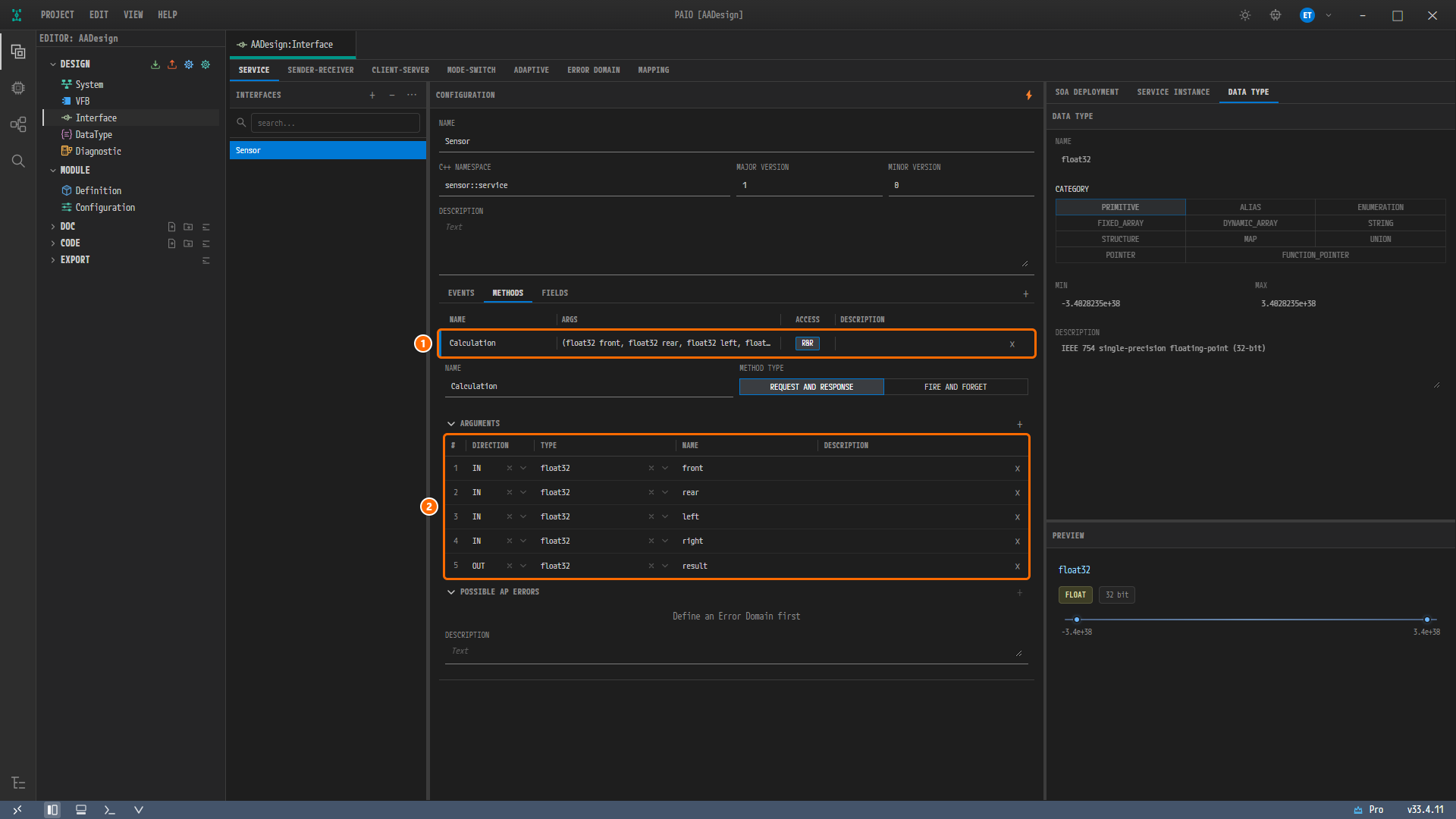
Figure 5-8. The editor after saving. ① The row header
Calculation(float32 front, float32 rear, float32 left, float…R&Rin the METHODS table, ② the five rows1 IN float32 front,2 IN float32 rear,3 IN float32 left,4 IN float32 right,5 OUT float32 resultin the ARGUMENTS table. The tabAADesign:Interfacecarries no modified mark ●. The DATA TYPE panel on the right shows the last chosen typefloat32(PRIMITIVE, MIN-3.4028235e+38, MAX3.4028235e+38, DESCRIPTIONIEEE 754 single-precision floating-point (32-bit), PREVIEWFLOAT32 bit).
The EDITOR view does not change. The Interface row under DESIGN is always shown whether or not the file exists. The Explorer, which lists the project's files, now shows INTERFACE.io.model in the design folder. The content of the saved design/INTERFACE.io.model is as follows (the date fields and the empty collections are shortened).
{
  "$schema": "https://autosar.io/schemas/interface.schema.json",
  "version": "2.0.0",
  "metadata": { "name": "Interface Dictionary" },
  "sender-receivers": [],
  "client-servers": [],
  "service-interfaces": [
    {
      "name": "Sensor",
      "major-version": 1,
      "minor-version": 0,
      "cpp-namespace": "sensor::service",
      "events": [ { "name": "SensorData", "type": "ByteArray" } ],
      "methods": [
        {
          "name": "Calculation",
          "fire-and-forget": false,
          "arguments": [
            { "name": "front",  "type": "float32", "direction": "in" },
            { "name": "rear",   "type": "float32", "direction": "in" },
            { "name": "left",   "type": "float32", "direction": "in" },
            { "name": "right",  "type": "float32", "direction": "in" },
            { "name": "result", "type": "float32", "direction": "out" }
          ]
        }
      ],
      "fields": []
    }
  ],
  "mode-switches": []
}
service-interfaces holds only Sensor. REQUEST AND RESPONSE is stored as "fire-and-forget": false, and an empty DESCRIPTION is stored without its key. The other collections such as sender-receivers are written as [] even though they are empty. SERVICE.io.model is not created in this chapter; it is first created in SOME/IP Deployment and Service Instances.
Viewing the Validation Result
-
Look at the V icon in the footer at the bottom of the window, the fifth icon from the left. It carries no badge.
-
Look at the VALIDATION panel. If it is closed, click the V icon in the footer.

Figure 5-9. The VALIDATION panel after saving the service interface. The header carries no badge, and under the column headers ELEMENT TYPE, NAME, DESCRIPTION and CONSTR there is the single line
No validation issues..
Since the types of the event and the arguments all point to types that exist in the DataType editor, there are no broken references. The Interface editor has no VALIDATION area of its own like the DataType editor. If you clear the TYPE of the event or of an argument with its ×, the field turns red with Type is required (in the ARGUMENTS table, as the cell's tooltip), the V icon gets a red badge 1, and this panel lists an error such as "SensorData" of "Sensor": Type is required. until you pick a type again. An empty DIRECTION turns its cell red, with the tooltip Direction is required, but adds no row to this panel.
Why Is It Designed This Way?
- There is exactly one service interface,
Sensor. The Interface file of the reference design holds only theSERVICE-INTERFACESensor, which has the eventSensorDataand the methodCalculationand no fields. If you follow the inputs of this chapter exactly, the Interface file in ARXML Export is byte-for-byte identical to the reference design. - The C++ namespace
sensor::servicebecomes theNAMESPACESof the export. It comes out split into twoSYMBOL-PROPS,sensorandservice. If you leave it empty, no namespace appears in the export. - The version
1/0is the default and also the reference value. The reference design hasMAJOR-VERSION1andMINOR-VERSION0, so they are left untouched. - The type of the event
SensorDataisByteArray. In the reference design, theVARIABLE-DATA-PROTOTYPESensorDatapoints to/DataTypes/CppImplementationDataTypes/ByteArray. The dropdown lists only the types that exist in the DataType editor, which is why Data Types comes before this chapter. - The method
CalculationisREQUEST AND RESPONSE. In the reference design, theCLIENT-SERVER-OPERATIONCalculationhasFIRE-AND-FORGETfalse. The editor's default is already that value, so METHOD TYPE is not changed. - For the five arguments you pick
float32in the UI. In the reference design, theARGUMENT-DATA-PROTOTYPEfront,rear,leftandrightareIN,resultisOUT, and all of them have the type/DataTypes/CppImplementationDataTypes/float. The editor's primitivefloat32comes out under its C++ namefloatin ARXML Export. The argument order must also match the table. - No SOME/IP deployment is created in this chapter. The SOA DEPLOYMENT panel on the right stays at
No deployments configuredand is filled in SOME/IP Deployment and Service Instances.
Checklist
- The SERVICE tab of the tab
AADesign:Interfaceis active and the INTERFACES list holds the single entrySensor. - With
Sensorselected, NAME isSensor, C++ NAMESPACE issensor::service, MAJOR VERSION is1, MINOR VERSION is0, and DESCRIPTION is empty. - The EVENTS table holds the single row
SensorDataByteArray. - The METHODS table holds the single row
Calculation, its ARGS is(float32 front, float32 rear, float32 left, float32 right) → CalculationOutput, and its ACCESS isR&R. - The ARGUMENTS table of
Calculationhas the five rows1 IN float32 front,2 IN float32 rear,3 IN float32 left,4 IN float32 right,5 OUT float32 result. - The FIELDS subtab is empty.
- The tab
AADesign:Interfacecarries no modified mark ● and the filedesign/INTERFACE.io.modelexists. - The VALIDATION panel shows
No validation issues.and the header carries no badge.
Next Step
In SOME/IP Deployment and Service Instances you use the SOA DEPLOYMENT panel on the right to create the SOME/IP deployment (service ID 11) and the service instances for the interface Sensor.