Executables and Processes
What You Will Do
In this chapter you double-click each of the five Adaptive Applications created in Adaptive Applications and Ports to open the AA Internal Behavior dialog, check the Executable in the EXECUTION tab and add one Process to each.
The Executable is already filled in, so you type nothing there. For the Process you enter a name, ENTER TIMEOUT and EXIT TIMEOUT in STARTUP CONFIG, a state of MachineFG under FUNCTION GROUP STATE, and, for Sensor, Fusion and Actuator, an EXECUTION DEPENDENCY that requires the CM process to be Running. You create CM first, follow Sensor as a procedure, and repeat the remaining three from a table. Finally you open the PROCESSES tab of the Machine Configuration dialog to confirm that the five processes are gathered on the machine.
When you finish this chapter, each of the five *.swc.io.model files in design/SWC/AdaptiveApplication/ holds an executable and a process. In ARXML Export these become the reference design's five EXECUTABLE elements, five PROCESS elements, five STARTUP-CONFIG elements and the FUNCTION-GROUP-STATE-IREF and EXECUTION-DEPENDENCY elements.
Before You Begin
- Start from the state at the end of Adaptive Applications and Ports. The five files
Sensor,Fusion,Actuator,CMandEMindesign/SWC/AdaptiveApplication/have noexecutableand noprocessyet. - The machine
Ecuhas the single function groupMachineFGseen in Machine Configuration, with the statesOff,Startup,Shutdown,RestartandVerify. The FUNCTION GROUP STATE of this chapter picks a state of that function group, soMachineFGmust exist on the machine. - The VALIDATION panel shows
No validation issues.. - Order matters. Create and save
CMfirst. The PROCESS list under EXECUTION DEPENDENCY offers only processes that other Adaptive Applications in the same compositionHPChave already saved, so the process ofCMmust be saved beforeSensor,FusionandActuatorcan pickCM.
The only things you type on the keyboard in this chapter are the five process names and the timeout numbers. Everything else is picked by clicking the + buttons and the dropdowns. The values of the Executable section are all pre-filled and are not changed.
| Adaptive Application | Process NAME | ENTER TIMEOUT / EXIT TIMEOUT | FUNCTION GROUP STATE | EXECUTION DEPENDENCY |
|---|---|---|---|---|
CM | CM | 1 / 1 (default, unchanged) | MachineFG : Startup, MachineFG : Shutdown, MachineFG : Restart, MachineFG : Verify | none |
Sensor | Sensor | 5 / 5 | MachineFG : Startup | CM : Running |
Fusion | Fusion | 5 / 5 | MachineFG : Startup | CM : Running |
Actuator | Actuator | 5 / 5 | MachineFG : Startup | CM : Running |
EM | EM | 0 / 0 | MachineFG : Startup | none |
Leave the timeout unit at its default s. SCHEDULING POLICY stays SCHED_OTHER and SCHEDULING PRIORITY stays 0, the defaults, for all five.
Creating the Executable and Process of CM
Opening the AA Internal Behavior Dialog
-
In the EDITOR view on the left, click VFB under DESIGN. The tab
AADesign:VFBopens with the composition nodeHPC [Ecu]on the root canvas. Double-click the nodeHPC [Ecu]. The breadcrumb changes toSystem > HPC, and the frameHPCshows the five nodes and two connectors created in chapter 8. If the tabAADesign:VFBfrom chapter 8 is still open and its breadcrumb already readsSystem > HPC, go straight to step 2. -
Double-click the node
CM.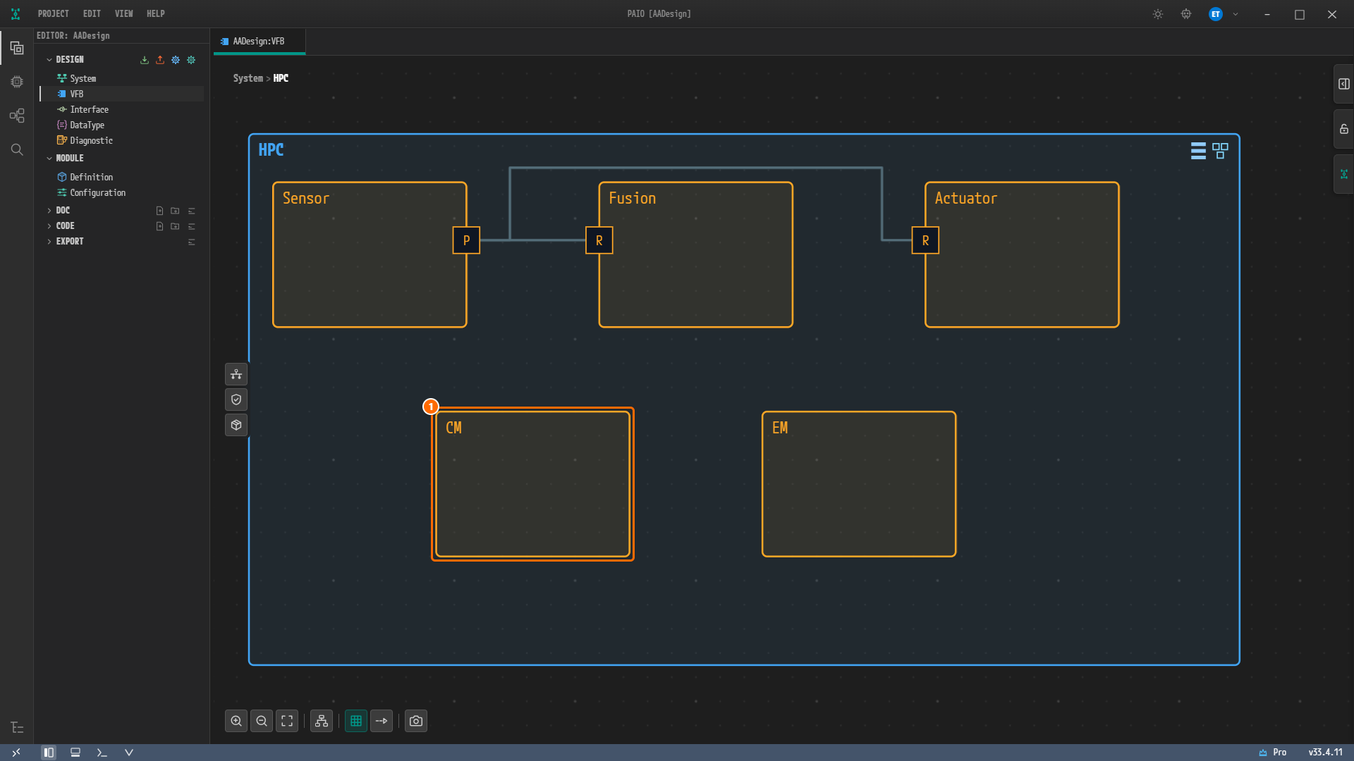
Figure 9-1. The VFB editor inside the composition
HPC. ① The nodeCMto double-click.Sensor,FusionandActuatorare in the top row,CMandEMin the bottom row, and lines run from thePofSensorto the twoRports. The node arrangement may differ from the figure depending on the result of Auto Layout in chapter 8; it has no effect on the design values. -
The dialog AA Internal Behavior [CM] opens. The canvas on the left shows the body of
CMwith no ports. The panel on the right has two tabs, PROPERTIES and EXECUTION; PROPERTIES is open at first and shows NAMECM, AS PROTOTYPECM, DESCRIPTION-and PORTSNo ports available. A Close button sits at the bottom.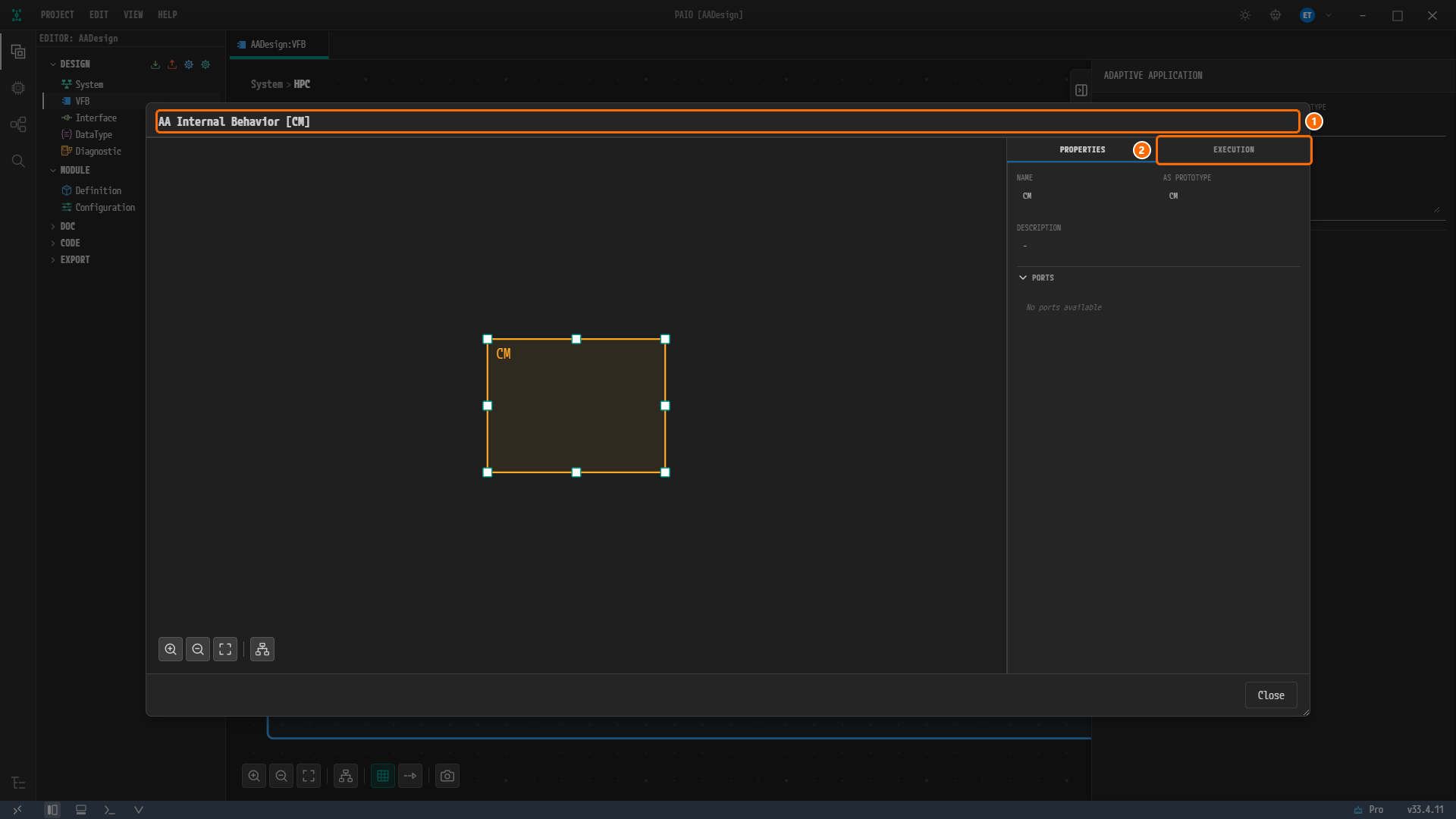
Figure 9-2. The dialog just after opening. ① The title AA Internal Behavior [CM], ② the tab EXECUTION. The PROPERTIES tab shows the name and ports entered in chapter 8 as read-only.
Checking the EXECUTABLE Section of the EXECUTION Tab
-
Click the tab EXECUTION. The EXECUTABLE section is at the top; below it are the PROCESS header with a + button (tooltip Add Process) and the text
No processes defined. -
Only check the values of the EXECUTABLE section. Type nothing.
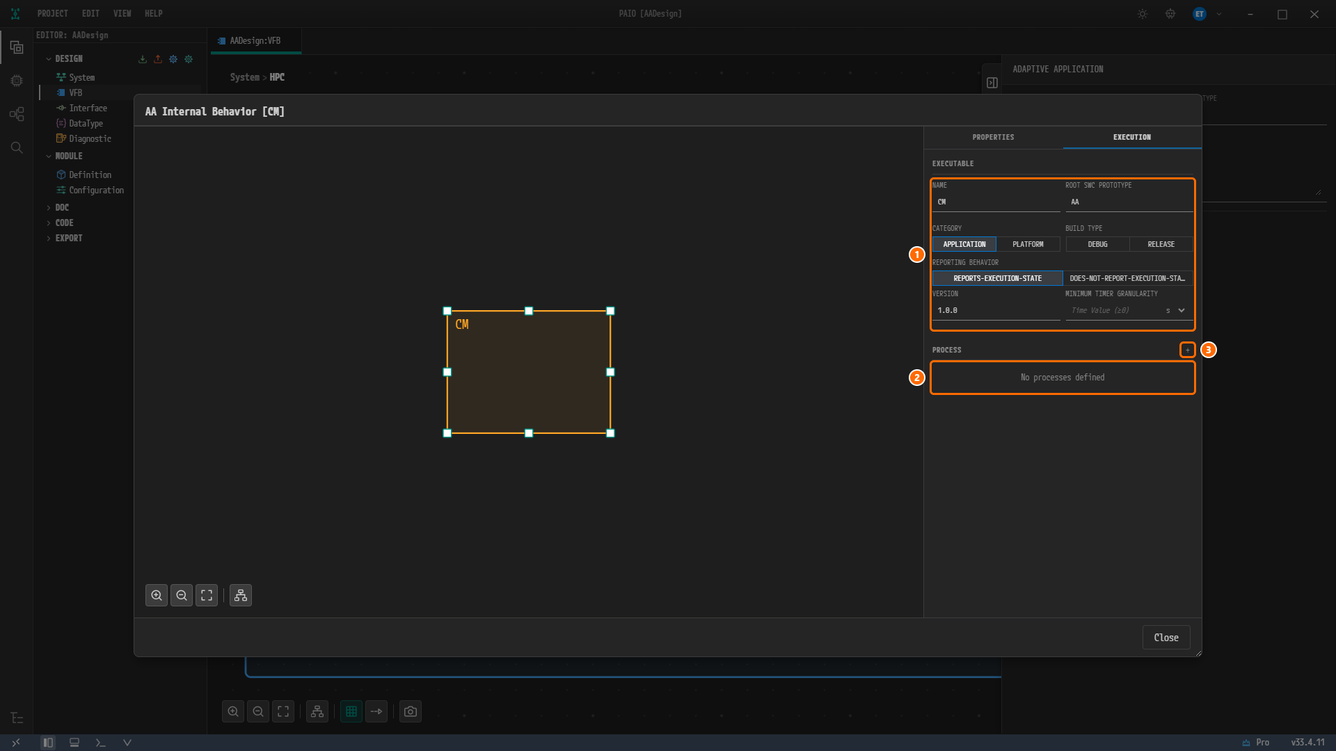
Figure 9-3. The EXECUTION tab when first opened. ① The EXECUTABLE section, ②
No processes defined, ③ the + button to the right of the PROCESS header (tooltip Add Process).Label Value Note NAME CMPre-filled with the Adaptive Application name ROOT SWC PROTOTYPE AADefault CATEGORY APPLICATIONToggle APPLICATION/PLATFORMBUILD TYPE empty Toggle DEBUG/RELEASE, both off. Do not turn either onREPORTING BEHAVIOR REPORTS-EXECUTION-STATEToggle REPORTS-EXECUTION-STATE/DOES-NOT-REPORT-EXECUTION-STATEVERSION 1.0.0Default MINIMUM TIMER GRANULARITY empty Placeholder Time Value (≥0), units. Do not enter anythingAll five Adaptive Applications show the same values; only NAME carries each one's own name.
Adding a Process and Entering Its Name
-
Click the + button to the right of the PROCESS header. A card
CM_0appears, collapsed. Do not press the × at the right of the card header (tooltip Remove Process). -
Click the card header
CM_0to expand it. Inside are a NAME field and the accordions STARTUP CONFIG, FUNCTION GROUP STATE, EXECUTION DEPENDENCY, LOG CONFIG and DLT CONTEXTS; only STARTUP CONFIG is expanded. -
Type
CMinto NAME and pressTab. The card header changes toCM, and the dialog title reads● AA Internal Behavior [CM]with the modified mark. -
Leave STARTUP CONFIG as it is. The default timeouts
1 s/1 sofCMare exactly the values of the reference design.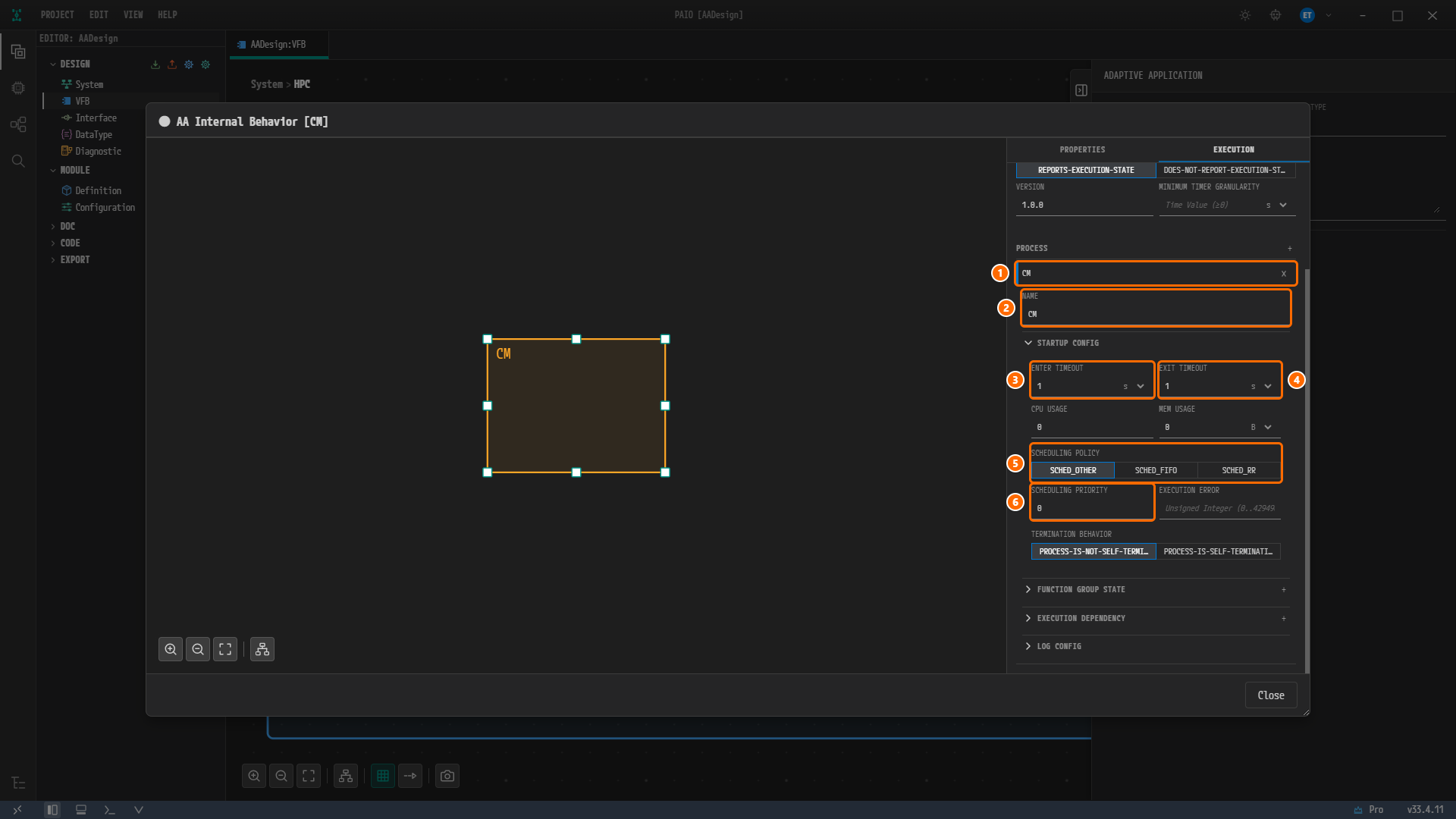
Figure 9-4. The process card after entering the name. ① The card header
CM, ② NAME =CM, ③ ENTER TIMEOUT1s, ④ EXIT TIMEOUT1s, ⑤ SCHEDULING POLICY =SCHED_OTHER, ⑥ SCHEDULING PRIORITY =0. The title reads● AA Internal Behavior [CM].STARTUP CONFIG label Default In this chapter ENTER TIMEOUT 1sChange to 5forSensor,FusionandActuator, and to0forEMEXIT TIMEOUT 1sSame as above CPU USAGE 0Unchanged MEM USAGE 0BUnchanged SCHEDULING POLICY SCHED_OTHERToggle SCHED_OTHER/SCHED_FIFO/SCHED_RR. UnchangedSCHEDULING PRIORITY 0Unchanged EXECUTION ERROR empty Placeholder Unsigned Integer (0..4294967295). UnchangedTERMINATION BEHAVIOR PROCESS-IS-NOT-SELF-TERMINATINGToggle PROCESS-IS-NOT-SELF-TERMINATING/PROCESS-IS-SELF-TERMINATING. Unchanged
Adding Four Function Group States
The CM process is bound to four states of MachineFG: Startup, Shutdown, Restart and Verify. You repeat the procedure of creating one row and picking its state four times.
-
Click the accordion header FUNCTION GROUP STATE to expand it. The body reads
No function group states defined. -
Click the + button to the right of the header (tooltip Add Function Group State). A row
MachineFG : Offappears. The default is the machine's first function group and that group's first state. -
Click the row header
MachineFG : Offto expand it. The FUNCTION GROUP field showsMachineFGand the FUNCTION GROUP STATE field showsOff. -
Click the FUNCTION GROUP STATE field. The dropdown lists
Off(the current value, with a check mark),Startup,Shutdown,RestartandVerify, in that order.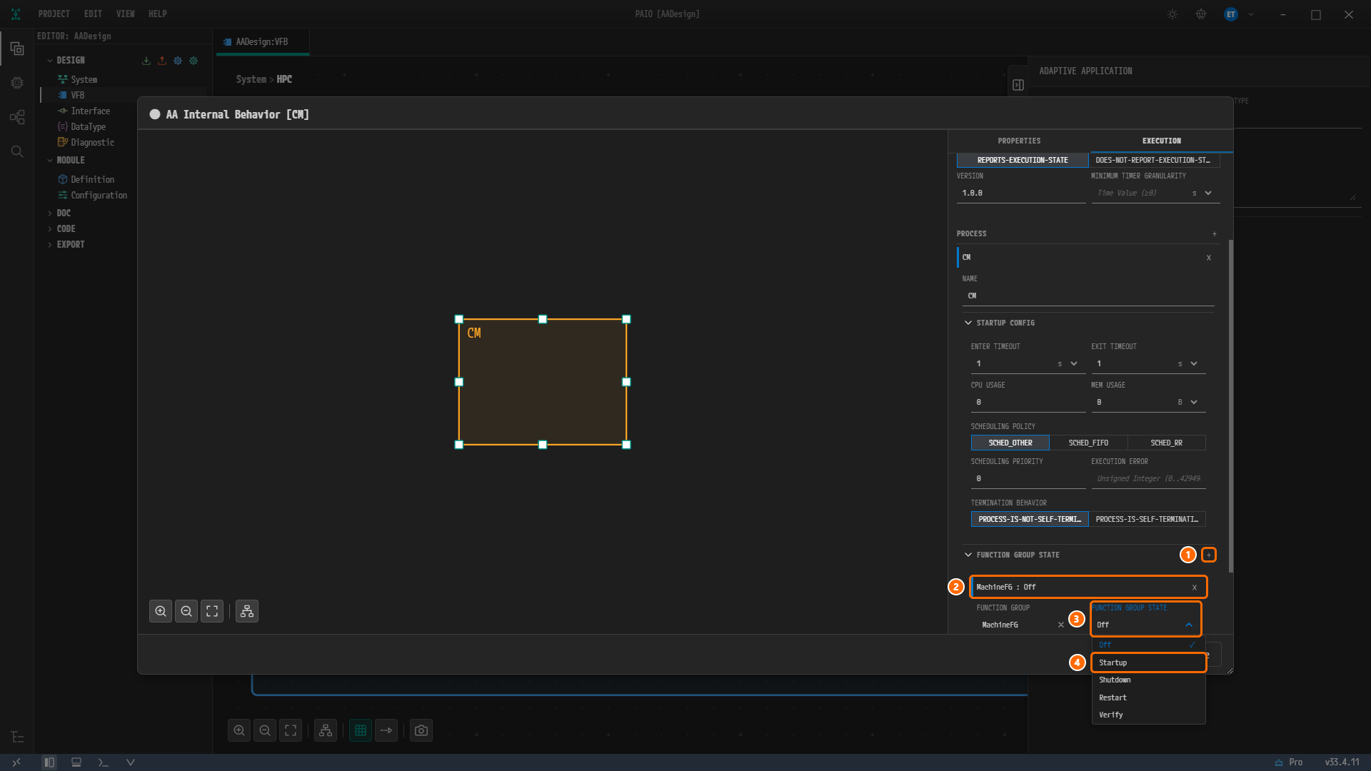
Figure 9-5. The state dropdown of the first row. ① The + button of the FUNCTION GROUP STATE header, ② the new row
MachineFG : Off, ③ the FUNCTION GROUP STATE field, ④ the dropdown itemStartup. The FUNCTION GROUP field showsMachineFG. The dropdown overlaps the Close button. -
Click
Startup. The row header changes toMachineFG : Startup. Click the row header again to collapse it. -
Repeat steps 2 to 5 three more times, picking
Shutdown,RestartandVerify. Each new row is created asMachineFG : Off, so pick the state as soon as the row appears. Do not press the × at the end of a row (tooltip Remove Function Group State). -
Click the accordion header EXECUTION DEPENDENCY to expand it and look. The body reads
No execution dependencies defined.CMhas no dependency, so leave it.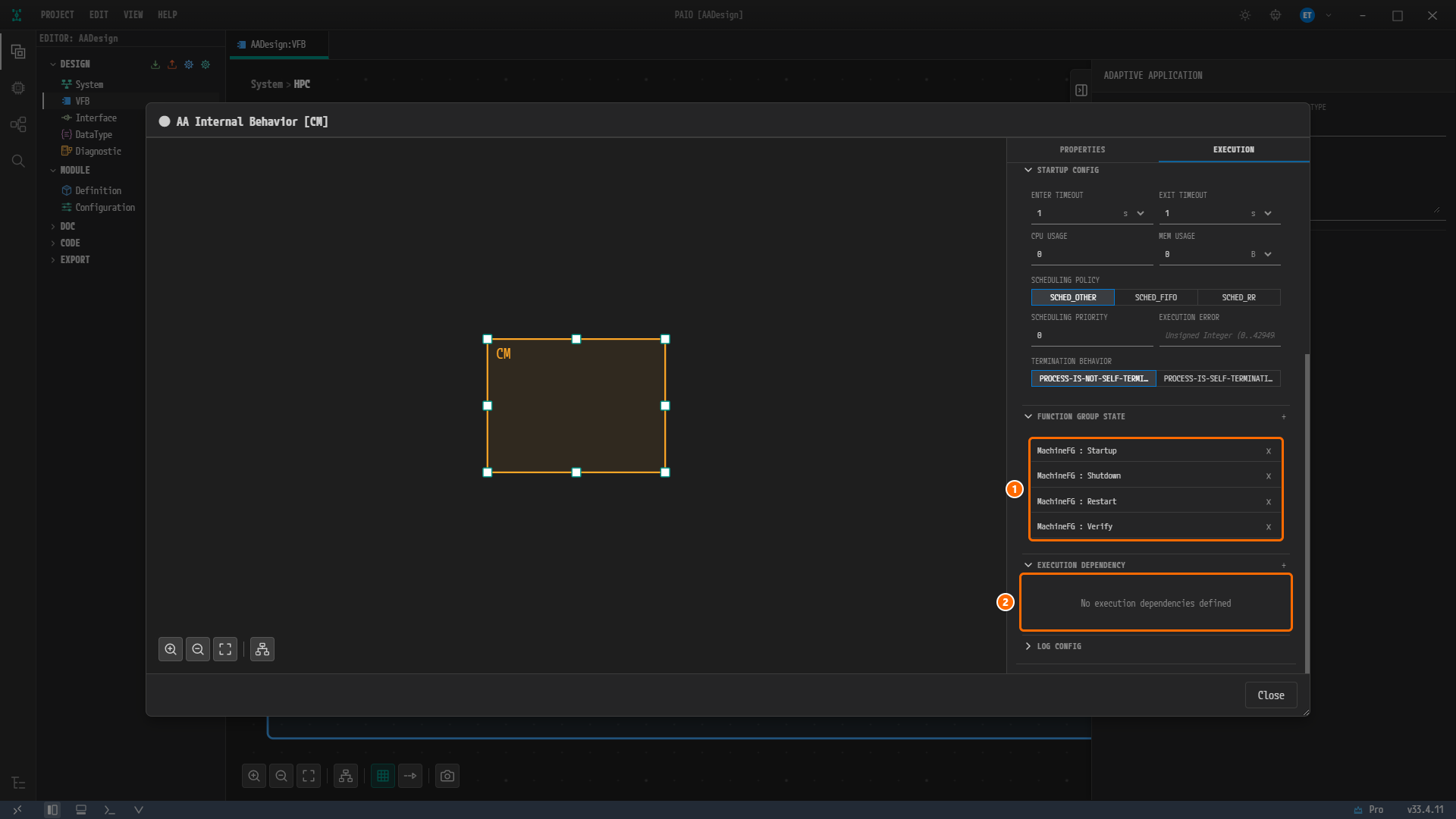
Figure 9-6. The card after all four rows are created. ① The rows
MachineFG : Startup,MachineFG : Shutdown,MachineFG : RestartandMachineFG : Verify, ②No execution dependencies definedunder EXECUTION DEPENDENCY.
Caution. The default state of a new row is
Off. No process in the reference design is bound toOff, so you must change the state every time you create a row. A row left atOffgoes into the saved file as it is.
Saving and Closing
-
Press
Ctrl+Sinside the dialog. The●disappears from the title, which becomesAA Internal Behavior [CM]. The tab stays on EXECUTION. -
Click Close. Because the dialog is saved, it closes without asking.
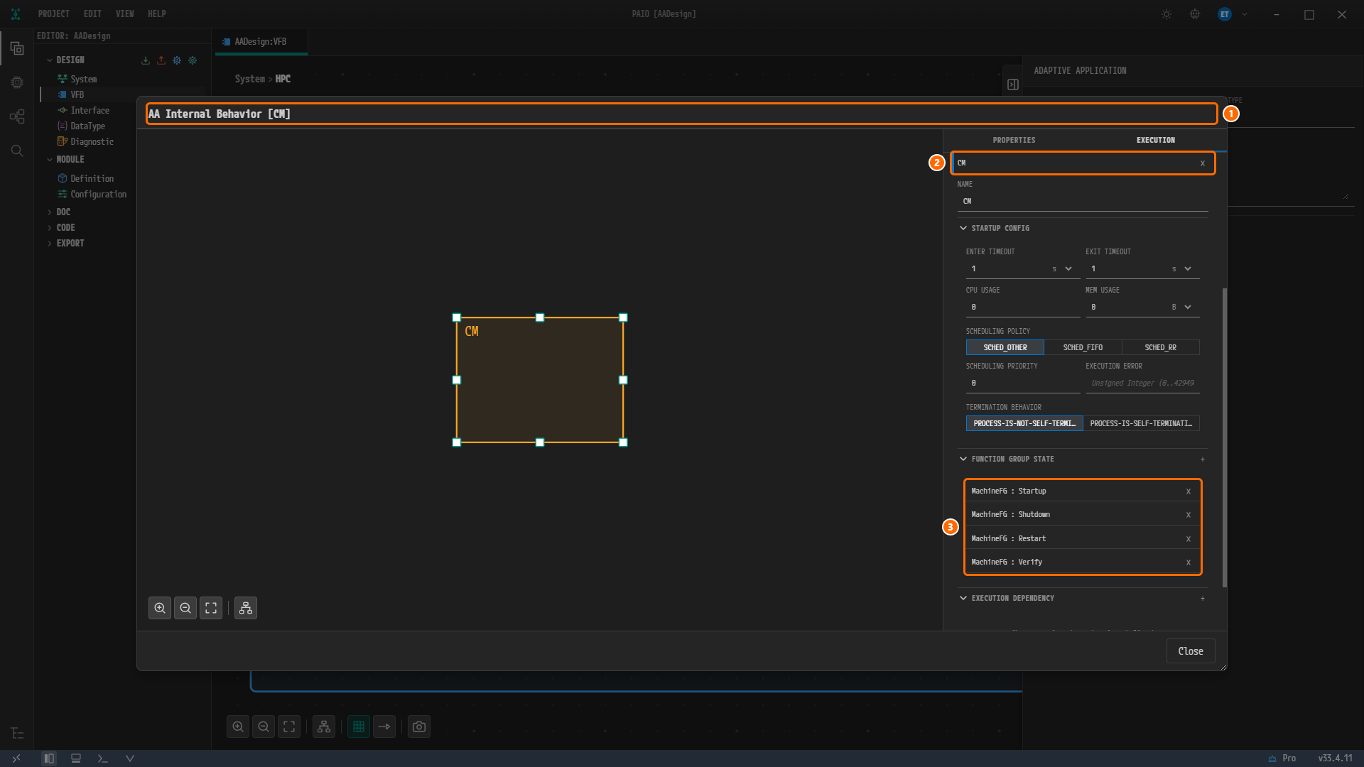
Figure 9-7. The dialog after saving. ① The title
AA Internal Behavior [CM](no modified mark), ② the card headerCM, ③ the four FUNCTION GROUP STATE rows. Saving leaves the accordions as they were, so EXECUTION DEPENDENCY is still expanded; its bodyNo execution dependencies definedis cut off at the lower edge of the panel.
Note.
Ctrl+Sinside the dialog writesCM.swc.io.modeland also saves theAADesign:VFBtab. After closing, the tab has no modified mark●. If you click Close without saving, aDo you want to save the changes?dialog appears with the buttons Save, Don't Save and Cancel. In this chapter you always save withCtrl+Sand then click Close.
Creating the Process of Sensor
Sensor is a process whose timeouts change and that gets an execution dependency. Fusion and Actuator have the same values.
Creating the Card and Entering the Timeouts
-
Double-click the node
Sensor. AA Internal Behavior [Sensor] opens, and the canvas shows the body ofSensorwith thePportSensoron its edge. -
Click the tab EXECUTION and click the + button of PROCESS. A card
Sensor_0appears. Click its header to expand it. -
Type
Sensorinto NAME and pressTab. -
In STARTUP CONFIG, type
5into ENTER TIMEOUT and pressTab, then type5into EXIT TIMEOUT and pressTab. Leave the unitsas it is.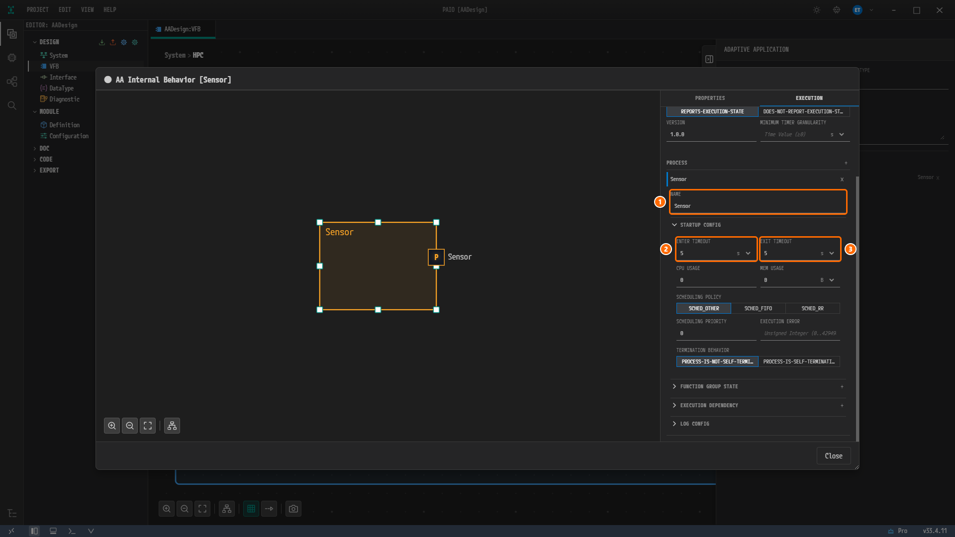
Figure 9-8. The card after entering the timeouts. ① NAME =
Sensor, ② ENTER TIMEOUT =5s, ③ EXIT TIMEOUT =5s. The title reads● AA Internal Behavior [Sensor], and the canvas shows thePportSensor.
Adding the Function Group State
-
Click the FUNCTION GROUP STATE header to expand it and click the + button. A row
MachineFG : Offappears. -
Click the row header to expand it and click
Startupin the FUNCTION GROUP STATE field. The row becomesMachineFG : Startup. Click the row header again to collapse it.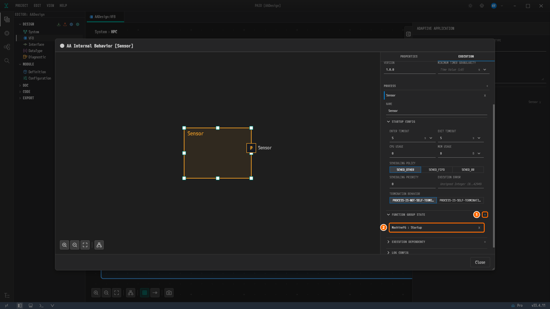
Figure 9-9. FUNCTION GROUP STATE after picking the state. ① The + button, ② the row
MachineFG : Startup(collapsed). EXECUTION DEPENDENCY is still collapsed.
Adding the Execution Dependency
-
Click the EXECUTION DEPENDENCY header to expand it. The body reads
No execution dependencies defined. -
Click the + button to the right of the header (tooltip Add Execution Dependency). A row
CM : Runningappears. -
Click the row header to expand it. The PROCESS field shows
CMand the PROCESS STATE field showsRunning. -
Click the PROCESS field to open the dropdown. Its only item is
CM, becauseCMis the only other Adaptive Application in this composition that has saved a process so far. The items of the PROCESS STATE dropdown areIdle,Starting,RunningandTerminated.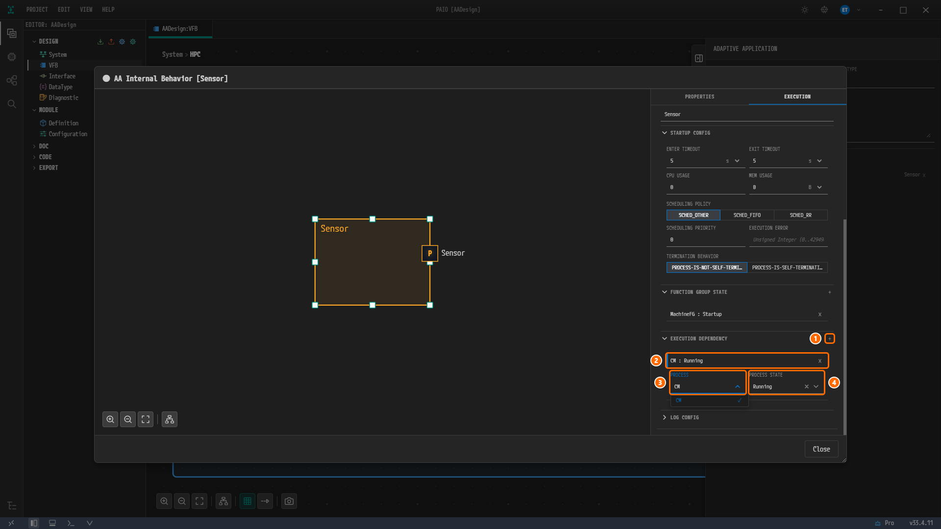
Figure 9-10. The execution dependency row expanded. ① The + button of the EXECUTION DEPENDENCY header, ② the new row
CM : Running, ③ the PROCESS field with its dropdown open (itemCM, check mark), ④ PROCESS STATE =Running. -
Click
CM. Leave PROCESS STATE atRunning. -
Press
Ctrl+S, then click Close.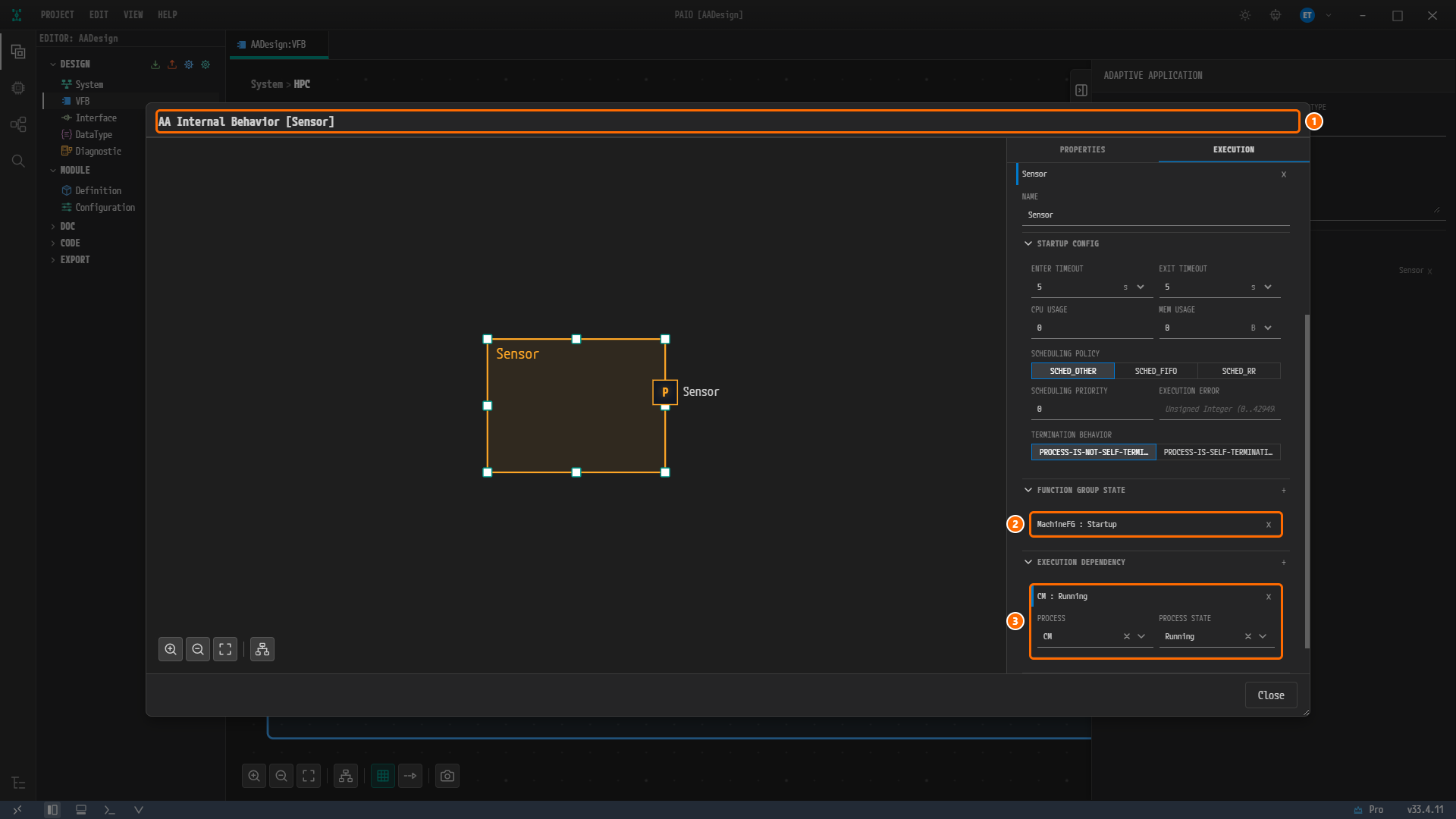
Figure 9-11. The
Sensordialog after saving. ① The titleAA Internal Behavior [Sensor], ② the FUNCTION GROUP STATE rowMachineFG : Startup, ③ the EXECUTION DEPENDENCY rowCM : Running(PROCESSCM, PROCESS STATERunning). STARTUP CONFIG shows5s/5s.
Creating the Processes of Fusion, Actuator and EM
Create the remaining three the same way. Double-click the node, press + in the EXECUTION tab to create the card, enter the values from the table, and finish with Ctrl+S and Close.
| Node | NAME | ENTER TIMEOUT / EXIT TIMEOUT | FUNCTION GROUP STATE | EXECUTION DEPENDENCY |
|---|---|---|---|---|
Fusion | Fusion | 5 / 5 | MachineFG : Startup | Create a row with + and change PROCESS to CM. PROCESS STATE stays Running |
Actuator | Actuator | 5 / 5 | MachineFG : Startup | Same as above |
EM | EM | 0 / 0 | MachineFG : Startup | none |
Caution. In
FusionandActuator, pressing + under EXECUTION DEPENDENCY creates a row whose default isSensor : Running. The default is the first process in the list, and the list isSensor,CMinFusionandSensor,Fusion,CMinActuator. Expand the row and pickCMin the PROCESS field without fail. Confirm that the row header readsCM : Runningbefore saving.
For EM, type 0 into both timeout fields. The EM of the reference design has no timeout values; when you enter 0, PAIO omits the timeout tags on ARXML export, which gives the same shape.
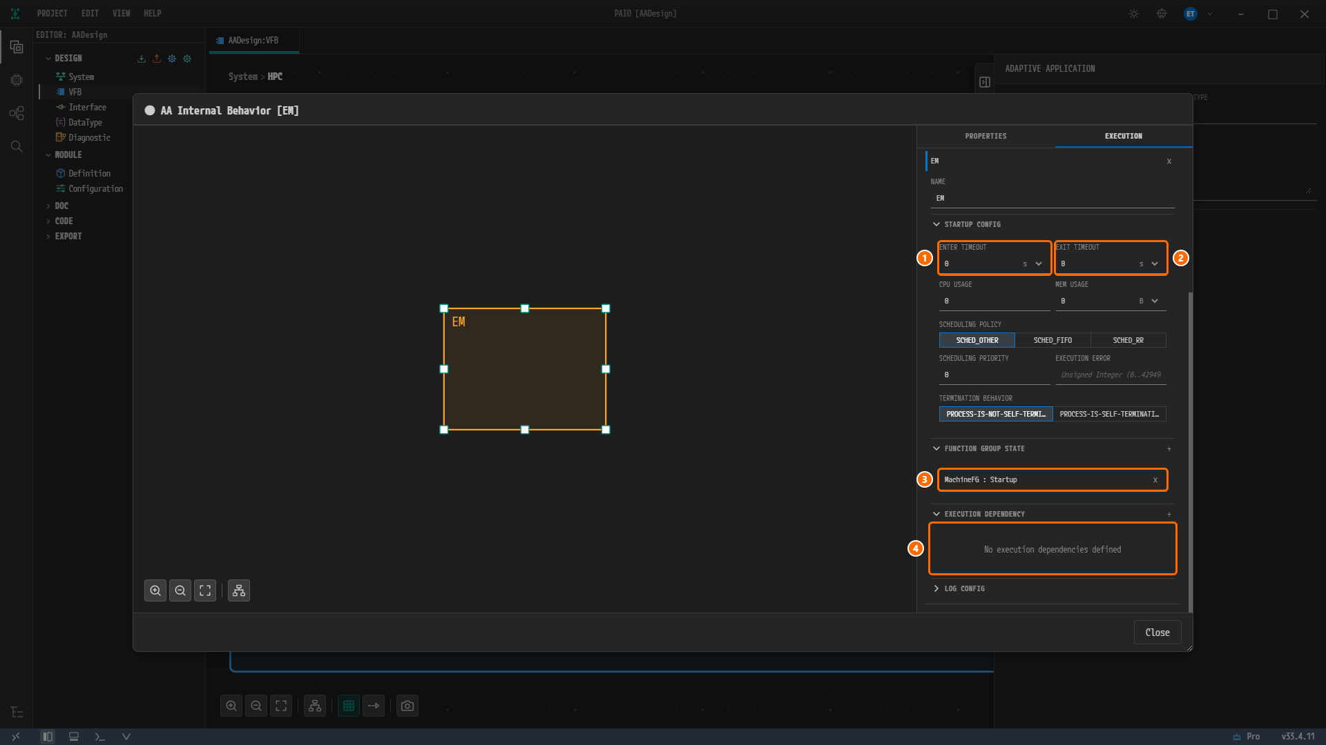
Figure 9-12. The EM card just before saving. ① ENTER TIMEOUT = 0 s, ② EXIT TIMEOUT = 0 s, ③ the row MachineFG : Startup, ④ No execution dependencies defined under EXECUTION DEPENDENCY. The title reads ● AA Internal Behavior [EM].
Once all five dialogs are saved, each file in design/SWC/AdaptiveApplication/ gains an executable and a process. The save also adds internal-behavior: runnable-entities and rte-events are empty, while canvas-size ({ "width": 160, "height": 120 }) and port-positions (the position of each port; {} for CM and EM, which have no ports) store the layout of the dialog canvas. The executable of CM.swc.io.model looks like this.
"executable": {
  "name": "CM",
  "root-swc-prototype": "AA",
  "version": "1.0.0",
  "category": "APPLICATION_LEVEL",
  "reporting-behavior": "REPORTS-EXECUTION-STATE"
}
The process holds the name and one entry of startup-configs (the function group states, resource-group with cpu-usage 0 and mem-usage 0, scheduling-policy SCHED_OTHER, scheduling-priority 0, enter-timeout and exit-timeout, and execution-dependencies). For Sensor, Fusion and Actuator, enter-timeout and exit-timeout are 5 and execution-dependencies is [{ "process-ref": "CM", "state": "Running" }]; for EM the timeouts are 0 and execution-dependencies is []. The on-screen CATEGORY APPLICATION is stored in the file as APPLICATION_LEVEL.
Note. Even though you never opened the LOG CONFIG accordion, a
log-configis saved insideprocessas well:application-idis an empty string,default-log-levelisINFO,log-modeisCONSOLEanddlt-contextsis[]. You fill in that empty APPLICATION ID in Logging and DLT. The empty value raises no validation finding.
Checking in the PROCESSES Tab of the Machine
You entered the processes one Adaptive Application at a time, but the machine gathers them into a single list.
-
Click
Systemin the breadcrumb above the canvas to return to the root. -
Click the machine icon in the header of the node
HPC. Machine Configuration [HPC] opens with the tabs MACHINE, FUNCTION GROUP, PROCESSES and MODULE. -
Click the tab PROCESSES. The PROCESSES list on the left holds the five entries
Sensor,Fusion,Actuator,CMandEM. In chapter 1 this list readNo Adaptive Application processes found in this Composition. -
Click
CMin the list. The header of the middle panel readsCM, with the buttons Mark as SM and Mark as PHM on the right. Press neither. Below follow the sections CORE AFFINITY, ADAPTIVE APPLICATION, STARTUP CONFIG, FUNCTION GROUP STATE and EXECUTION DEPENDENCY.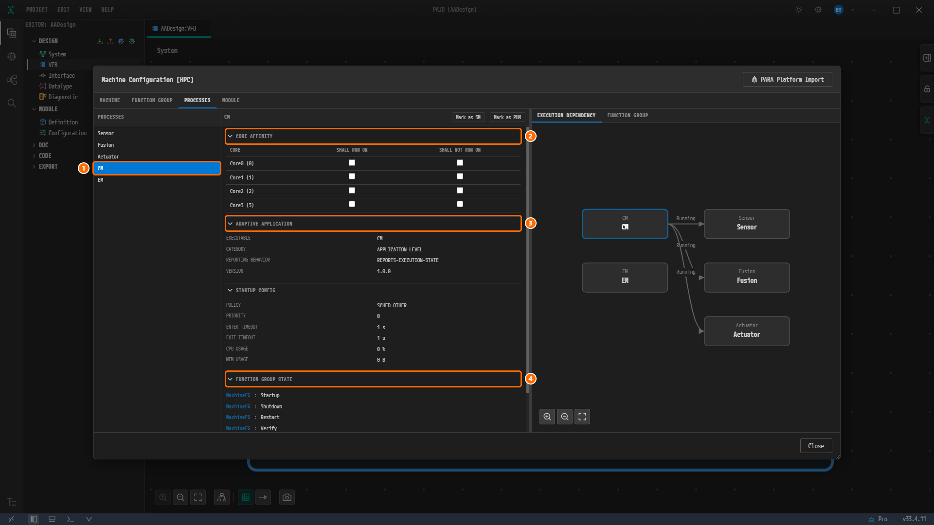
Figure 9-13. The PROCESSES tab with
CMselected. ①CMin the list, ② the CORE AFFINITY table (columns CORE, SHALL RUN ON, SHALL NOT RUN ON, rowsCore0 (0)toCore3 (3), all checkboxes empty), ③ ADAPTIVE APPLICATION (EXECUTABLECM, CATEGORYAPPLICATION_LEVEL, REPORTING BEHAVIORREPORTS-EXECUTION-STATE, VERSION1.0.0), ④ the four FUNCTION GROUP STATE rows. STARTUP CONFIG shows POLICYSCHED_OTHER, PRIORITY0, ENTER TIMEOUT1 s, EXIT TIMEOUT1 s, CPU USAGE0 %and MEM USAGE0 B. In the graph on the right,CMis highlighted with a blue border. -
Click
Sensorin the list and scroll the middle panel down. Under ADAPTIVE APPLICATION there areSWCSensorand the port rowPSensorSensor; STARTUP CONFIG shows ENTER TIMEOUT5 sand EXIT TIMEOUT5 s, FUNCTION GROUP STATE showsMachineFG : Startup, and EXECUTION DEPENDENCY showsCM : Running. -
Look at the tab EXECUTION DEPENDENCY of the panel on the right.
CMandEMare on the left,Sensor,FusionandActuatoron the right, and three arrows run fromCMto the three nodes, each labelledRunning. The selected process is highlighted with a blue border.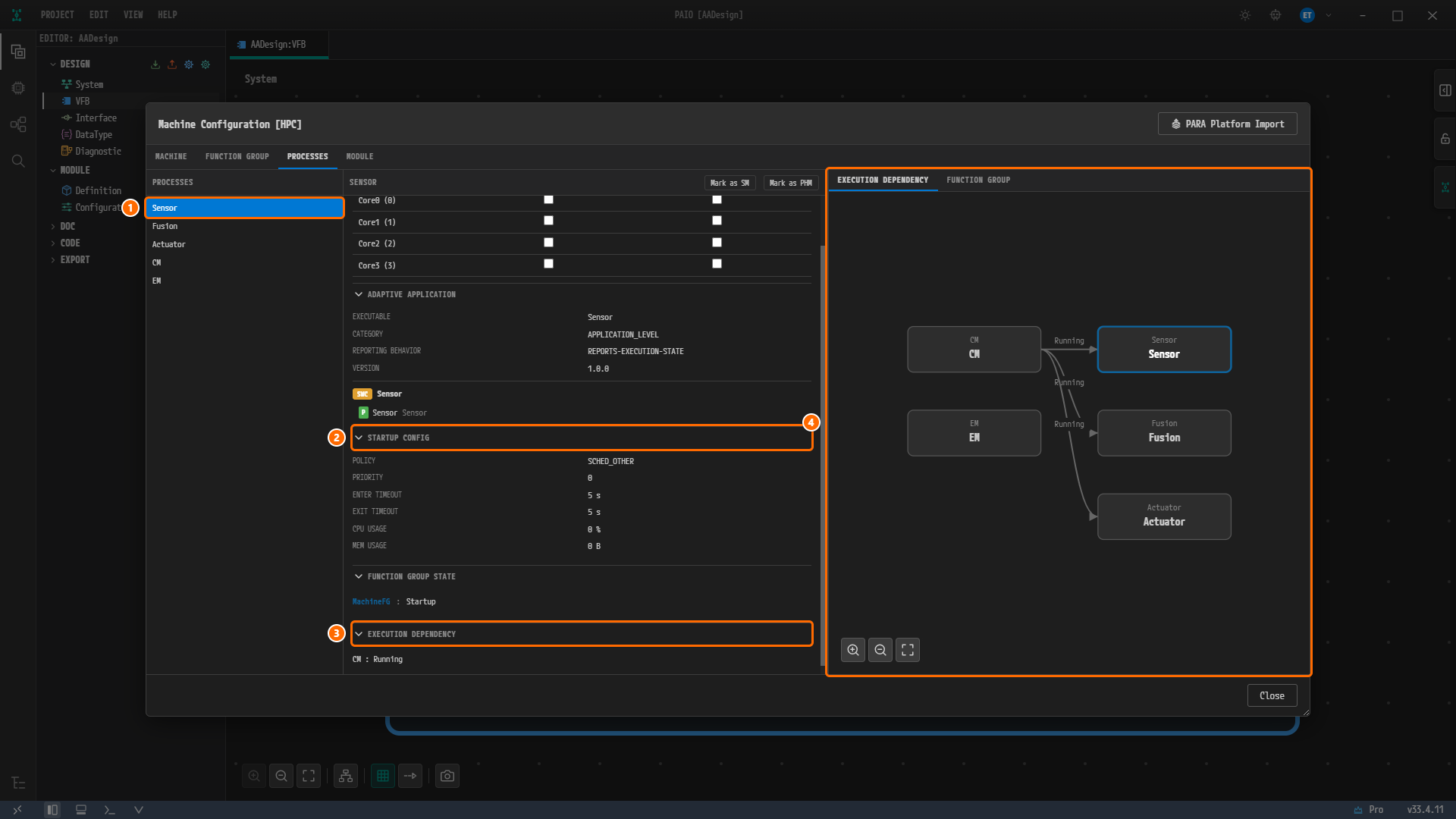
Figure 9-14. The tab with
Sensorselected. ①Sensorin the list, ② STARTUP CONFIG (5 s/5 s), ③ EXECUTION DEPENDENCYCM : Running, ④ the EXECUTION DEPENDENCY graph on the right. The three arrows fromCMtoSensor,FusionandActuatorcarry the labelRunning. -
Click Close. Nothing was changed, so it closes without asking.
Note. In the middle panel of this tab only the CORE AFFINITY checkboxes are editable; everything else is read-only. This tutorial does not check any core. The reference design has no mapping between processes and cores, and even without checking, the export contains a
PROCESS-TO-MACHINE-MAPPING-SETwith five mappings automatically. You see that in ARXML Export.
Viewing the Validation Result
-
Look at the V icon in the footer at the bottom of the window, the fifth icon from the left. It carries no badge.
-
Look at the VALIDATION panel. If it is closed, click the V icon in the footer. The header carries no badge, and under the column headers ELEMENT TYPE, NAME, DESCRIPTION and CONSTR the body reads
No validation issues..
Figure 9-15. The VALIDATION panel after all five dialogs are saved. The body reads
No validation issues..
Note. If you save after adding a process but before adding a FUNCTION GROUP STATE, validation reports a row such as
The process "EM" declares no functionGroupState; at least one is required.(it does not appear when you add the row first and then save, as this chapter does). You will meet this sentence again in Validation, where it is produced on purpose.
Why Is It Designed This Way?
- The Executable is not typed. The five
EXECUTABLEelements of the reference design all haveVERSION1.0.0,CATEGORYAPPLICATION_LEVELandREPORTING-BEHAVIORREPORTS-EXECUTION-STATE, with noBUILD-TYPEand noMINIMUM-TIMER-GRANULARITY. The dialog defaults match, so BUILD TYPE and MINIMUM TIMER GRANULARITY are left empty. - ROOT SWC PROTOTYPE is
AAfor all five. The reference design mixesAAforSensor,FusionandActuatorwithRootSwComponentforCMandEM. This tutorial keeps the defaultAAand makes all five uniform. Only the name differs; the design content is the same. - The timeouts are
5/5forSensor,FusionandActuator, and1/1forCM. The fiveSTARTUP-CONFIGelements of the reference design all useSCHED_OTHERand priority0, and theirENTER-TIMEOUT-VALUEandEXIT-TIMEOUT-VALUEare these values. TheSTARTUP-CONFIGofEMhas no timeout elements, so you enter0to have the tags omitted. CMis bound to the four states ofMachineFG, the others toStartup. TheFUNCTION-GROUP-STATE-IREFelements of the reference design are four forCM(Startup,Shutdown,Restart,Verify) and oneStartupeach forSensor,FusionandActuator.EMis bound toMachineFG : Startupas well, a departure from the reference design forced by validation. TheEMprocess of the reference design has noFUNCTION-GROUP-STATE-IREF. PAIO validation, however, rejects a process without a function group state withThe process "EM" declares no functionGroupState; at least one is required.. That is why this tutorial bindsEMtoStartupas well. The export then contains eightFUNCTION-GROUP-STATE-IREFelements, one more than the reference design.- The execution dependencies of
Sensor,FusionandActuatorpoint atRunningofCM. All threeEXECUTION-DEPENDENCYelements of the reference design point atProcessState/Runningof theCMprocess.CMandEMhave no dependency. - CPU USAGE and MEM USAGE stay at
0. The resource group of the reference design carries no values. In the export, a resource group withCPU-USAGE 0andMEM-USAGE 0is created on the machine side for each process, which differs in shape from the single shared resource group of the reference design. This difference cannot be produced through the UI.
Checklist
- Double-clicking the nodes
Sensor,Fusion,Actuator,CMandEMand opening the EXECUTION tab shows each one's own name in NAME of EXECUTABLE and1.0.0in VERSION. - Each PROCESS has one card, with the headers
CM,Sensor,Fusion,ActuatorandEM. - STARTUP CONFIG shows
1s/1sforCM,5s/5sforSensor,FusionandActuator, and0s/0sforEM. - FUNCTION GROUP STATE of
CMhas the four rowsMachineFG : Startup,MachineFG : Shutdown,MachineFG : RestartandMachineFG : Verify; the other four have the single rowMachineFG : Startup. There is noMachineFG : Offrow anywhere. - EXECUTION DEPENDENCY of
Sensor,FusionandActuatorhas the rowCM : Running;CMandEMshowNo execution dependencies defined. - Neither the dialog titles nor the tab
AADesign:VFBcarry the modified mark●. - The PROCESSES tab of Machine Configuration [HPC] lists the five processes, and the graph shows three
Runningarrows fromCMtoSensor,FusionandActuator. - The VALIDATION panel shows
No validation issues.and the header carries no badge.
Next Step
In Service Instance Mapping, you map the ports of Sensor, Fusion and Actuator to the SOME/IP service instances created in chapter 6.